Threadless Leadscrew ???
Posted by cozmicray
|
Re: Threadless Leadscrew ??? May 14, 2014 05:19PM |
Registered: 10 years ago Posts: 1,381 |
@dexterm2003:
Got a link to that pic.
Found it:
[www.zero-max.com]
Looks like they are using needle roller bearings, and shoulder screws.
Edited 1 time(s). Last edit at 05/14/2014 05:35PM by A2.
Found it:
[www.zero-max.com]
Looks like they are using needle roller bearings, and shoulder screws.
Edited 1 time(s). Last edit at 05/14/2014 05:35PM by A2.
|
Re: Threadless Leadscrew ??? May 14, 2014 08:14PM |
Registered: 10 years ago Posts: 20 |
I would agree that is the most likely configuration. The radial loading on the bearings would be better with needle bearings.
I hope to make a tilting radial indexing fixture for myself in the nearish future so that I can machine a set of threadless roller bearing carriages. I will post the result when I finish them.
I hope to make a tilting radial indexing fixture for myself in the nearish future so that I can machine a set of threadless roller bearing carriages. I will post the result when I finish them.
|
Re: Threadless Leadscrew Red 8 May 15, 2014 08:27PM |
Registered: 11 years ago Posts: 1,049 |
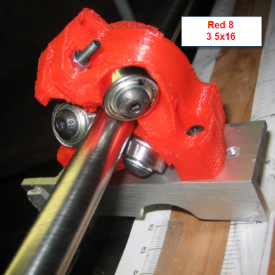
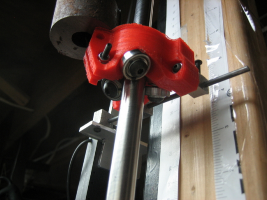
Another design / test Red 8
Rider based on Thingaverse 126537 with Three 5x16 mm bearings
Same 12mm rod, same test set up UGS - Arduino - GRBL - Nema 17 motor (24v)
Same DRO
Rider is tight on rod without compression (with compression bolt)
Quick test --- I'll gather more data and look for the errors / inaccuracies?

Rider based on Thingaverse 126537 with Three 5x16 mm bearings
Same 12mm rod, same test set up UGS - Arduino - GRBL - Nema 17 motor (24v)
Same DRO
Rider is tight on rod without compression (with compression bolt)
Quick test --- I'll gather more data and look for the errors / inaccuracies?

|
Re: Threadless Leadscrew Red 8 May 15, 2014 08:48PM |
Registered: 10 years ago Posts: 20 |
Did you correct the shaft wobble?
You could also try a range of length tests. Short ones and long ones to see if the accuracy is influenced by the distance traveled. Also you could adjust the starting position along the rod to see if different sections of the rod perform differently.
I would propose a sets of CMD 20, 50, 100, and maybe higher @ different starting positions some very slow 100 mm/sec and some medium speed 500 mm/sec. I realize that the goal is to get to higher speeds but we should characterize the behavior at low speeds as well to tell if there is a speed dependence in your results. It looks like the 2000 mm/sec has higher error than the 1000 mm/sec.
I have a feeling that this has fall less to do with the carriages and more to do with the experimental setup. That linear rod needs to be dead straight or you have no chance.
A video of the test from the view point of one of the bearing blocks might be helpful.
Keep it up!
|
Re: Threadless Leadscrew ??? May 16, 2014 04:54PM |
Registered: 11 years ago Posts: 1,049 |
|
Re: Threadless Leadscrew ??? May 16, 2014 06:12PM |
Registered: 10 years ago Posts: 20 |
That answers some big questions. I think that your big issue is your experimental setup. The flange bearings are not actually keeping the rod straight in the experimental setup. They are loose and they walk around as the shaft turns. I would look at the shaft couple that you have. A rigid shaft coupler is not going to work well for your test. The linear rod NEEDS to be perfectly straight and run perfectly true. If you have a flexible shaft coupling that would be your best bet. The carriage noticeably nods up and down as it moves along the rod and the source is not the shaft or carriage.
I would recommend a high rigidity zero backlash flexible coupling. You can get one from misumi for $22.25 + S&H Part number: MCGL25-5-12 I have attached the link below:
[us.misumi-ec.com]
One side of the coupling is 12mm the other is 5mm which are the size of your rod and the shaft of a NEMA 17 stepper.
Let me know what type of results you find once you change that part out.
,Michael
|
Re: Threadless Leadscrew ??? May 16, 2014 10:19PM |
Registered: 11 years ago Posts: 1,049 |
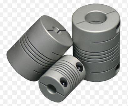
I am using a flexible 12mm - 5mm coupling to Nema 17 motor
Like these:
I have used ones that I have printed,
other couplers ended up with a lot of binding
I will tighten up and lock down the flange bearing mounting screws.
--- I may have loosened them up to prevent binding.
Motor mount allows motor to move around.
two flange bearings, coupler, motor mount , DRO coupling, rider -- all lead to binding in system
I don't have a steel 4 ft bar to set everything up on
Maybe I'll look for used optical bench?
I shouldn't have to use a titanium table test setup on a granite slab?????
Not going to be set up like that on Lisa, if ever works?

|
Re: Threadless Leadscrew ??? May 18, 2014 12:46AM |
Registered: 10 years ago Posts: 20 |
If there is binding that is a problem that needs to be addressed.
You shouldn't have to use an optical table, or a granite slab to make it work.
However you do need to address any and all sources of binding.
Loosening bearings may solve binding but it will kill accuracy and repeatability. The shaft needs to be solid and flange bearings fixed. The DRO needs to be parallel with the shaft as close as possible. The bracket that connects the carrier and the DRO might need to have a slot and pin joint to take make it somewhat flexible to avoid binding.
The motor should not need to wobble around. If you tighten up the flexible coupling to the two shafts that should get the alignment close and then lock tighten the motor into the motor mount. Any misalignment should be taken up in the flexible coupling with no issue.
Make sure that the shaft coupling that you are using runs true and does not induce in wobble in the shaft. A flexible beam coupling as you showed in the picture should work very nicely in a good setup. If you get binding with a flexible shaft coupling installed there are other issues that need to be addressed.
These are the keys to getting this setup to work properly. If you have this same setup on a granite table you will still have binding and repeatability problems if you don't address the brackets, shaft couplings and ensure that the DRO and shaft are as parallel as you can get.
Keep up the good work!
|
Re: Threadless Leadscrew ??? May 19, 2014 08:22AM |
Registered: 10 years ago Posts: 1,381 |
|
Re: Threadless Leadscrew ??? May 19, 2014 03:08PM |
Registered: 11 years ago Posts: 1,049 |
|
Re: Threadless Leadscrew ??? May 19, 2014 03:14PM |
Registered: 10 years ago Posts: 979 |
I think using a drill bit for a threaded rod is fine for a slow moving z like the Morgan does. However, it will probably never be a good solution for LISA.
ConceptFORGE
Wally, GUS Simpson, LISA Simpson, THOR Simpson, Sextupteron, CoreXZ
ConceptFORGE
Wally, GUS Simpson, LISA Simpson, THOR Simpson, Sextupteron, CoreXZ
|
Re: Threadless Leadscrew ??? May 19, 2014 04:42PM |
Registered: 10 years ago Posts: 1,381 |
A couple of experimental ideas:
Using the bearing edge, lap groves into a smooth rod, or convert the bearing into an electrode and EDM a grove.
Providing there is enough carbon in the steel, a side effect advantage of EDM machining is case hardening of the surface.
Electrical Discharge Machining with old Doorbell Parts
[www.youtube.com]
DIY Homemade EDM
The stepper circuit is based on the Langlois circuit. I have a flood system set up
[www.youtube.com]
EDM.MACHINE, part 1 - making the boxed way
[www.youtube.com]
How to Book EDM by Benjamin Fleming
[www.youtube.com]
DIY Wire EDM first test
[www.youtube.com]
EDM water quality testing
[www.youtube.com]
Wire EDM controlled by an Arduino MEGA 2560
[www.youtube.com]
|
Re: Threadless Leadscrew ??? May 19, 2014 06:46PM |
Registered: 10 years ago Posts: 20 |
@A2
While these techniques to add threads to a rod are interesting. This a tangent from the topic of a threadless roller bearing system.
I think that comzicray just needs to address the binding in the threadless design to get his setup repeatable.
There are things to consider to improve the threadless roller bearing system once it gets it up and going like magnetizing the bearings or rod in order to increase the thrust rating as well as possbily adding a thin rubber surface to rollers.
We need to stay focused though if we are going to really explore and improve threadless roller bearing systems.
@comzicray
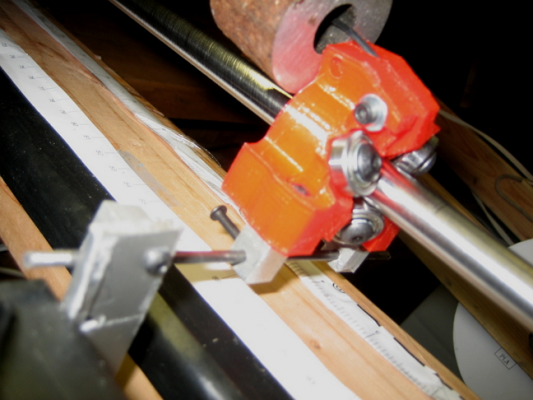
I was thinking about your setup and it is important to isolate the threadless rod and carriage from the DRO as much as possible and then only have a slot and pin connection with the DRO. This is how it would be in a printer setup.
I think that you need to add a feature to the carriage so that you can run it along the rod without it rotating. Something like a roller bogie on each side that would allow it to translate but not rotate relative to mount.
I would propose the following testing procedure to eliminate the binding problem.
1) Disconnect the DRO
2) Reinstall the flexbile shaft couplings.
3) Tighten the flange bearings.
4) Align the shaft with the motor as best you can with the motor mount loose
5) Tighten the motor mount.
6) Check for binding.
7) If there is no binding then proceed to adding the DRO back on. If there is binding check alignment of the motor mount and other involved components to determine what the cause is.
8) With the DRO back on, check for binding again.
9) If there is binding check to ensure that the DRO is parallel to the shaft in both axes.
10) Adjust and repeat as needed. If there is still binding you may need to add a pin and slot connection between the DRO and the carriage. This will allow the carriage to move the DRO but not allow the DRO alignment to bind the shaft.
Here is an example of a Delta bot that uses threadless roller bearings to what looks like good effect.
[letsmakerobots.com]
Keep up the good work!
|
Re: Threadless Leadscrew More Red_8 test May 19, 2014 07:22PM |
Registered: 11 years ago Posts: 1,049 |
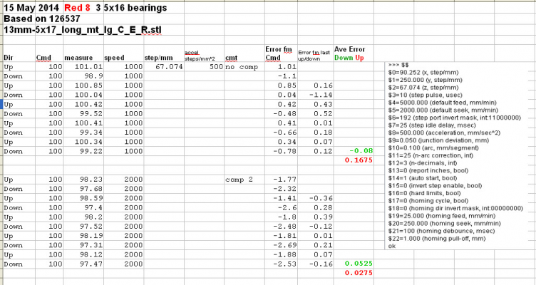
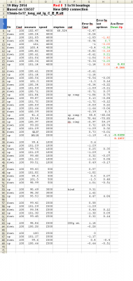
More Red_8 testing
Flange bearings are tight, Flex coupling there
same setup 24V, Nema 17, flex, 12mm rod
UGS -- Arduino -- GRBL -- motor
Rod is bent/bowed (I'll have video up soon)
Same DRO New DRO mount
There is a 208gram weight on it!
Here is the data:
Threadless Leadscrew ville not happy!

Flange bearings are tight, Flex coupling there
same setup 24V, Nema 17, flex, 12mm rod
UGS -- Arduino -- GRBL -- motor
Rod is bent/bowed (I'll have video up soon)
Same DRO New DRO mount
There is a 208gram weight on it!
Here is the data:
Threadless Leadscrew ville not happy!

|
Re: Threadless Leadscrew May 19, 2014 07:41PM |
Registered: 11 years ago Posts: 1,049 |
Here is an example of a Delta bot that uses threadless roller bearings to what looks like good effect.
[letsmakerobots.com]
Well that's it --- threadless Olympics over
I wonder what is the accuracy, repeatability?
design is he using Thingaverse 139425
Bearing guide? Lisa don't have one of those?
3 x 30 cm high quality steel rod leadscrew rod?
3 x 25 cm h9 stainless steel rod Guide rod?
30cm only 12"
No more testing, measuring, just build one like that??? DOAK!
Need stiff drink

|
Re: Threadless Leadscrew May 19, 2014 07:53PM |
Registered: 10 years ago Posts: 979 |
From reading the letsmakerobot post it doesn't seem like a tested design yet. You aren't out of the woods yet.
ConceptFORGE
Wally, GUS Simpson, LISA Simpson, THOR Simpson, Sextupteron, CoreXZ
ConceptFORGE
Wally, GUS Simpson, LISA Simpson, THOR Simpson, Sextupteron, CoreXZ
|
Re: Threadless Leadscrew ??? May 19, 2014 07:54PM |
Registered: 10 years ago Posts: 1,381 |
|
Re: Threadless Leadscrew ??? May 19, 2014 09:02PM |
Registered: 10 years ago Posts: 20 |
I agreed that the delta design that I posted is not tested to the rigor that we need.
I like the test that A2 posted. Yes it does appear to have too much deviation in that setup.
The next big questions would be to see if that experimental setup can be improved. Either by increasing the thrust rating to eliminate slip or to find the sources of deviation.
Possible sources of error:
Carriage slip? (due to acceleration/deceleration)
Dropped steps?
I wonder how a more traditional linear mechanism stacks up like a belt and cog or threaded rod? Any info on their repeatability?
I think that we could reduce carriage slippage if you magnetize the rod and make sure to eliminate jerk and reduce accel/decel.
Is they guy that put that video together active on the forum? If so we should get him to run some more experiments.
Good work everyone. Still more to do but hopefully we can find a way to get threadless ball screws to work repeatably
|
Re: Threadless Leadscrew More Red_8 test May 20, 2014 03:24PM |
Registered: 11 years ago Posts: 1,049 |
|
Re: Threadless Leadscrew More Red_8 test May 20, 2014 05:28PM |
Registered: 10 years ago Posts: 20 |
|
Re: Threadless Leadscrew More Red_8 test May 20, 2014 07:37PM |
Registered: 11 years ago Posts: 1,049 |
|
Re: Threadless Leadscrew More Red_8 test May 20, 2014 10:02PM |
Registered: 10 years ago Posts: 1,381 |
I noticed that the stepper motor is rotating, that will add to the error.
If you have an arbor press, V-blocks, and dial indicator you can straighten the rod.
Straighten shafts with pull down press
[www.youtube.com]
If you have an arbor press, V-blocks, and dial indicator you can straighten the rod.
Straighten shafts with pull down press
[www.youtube.com]
|
Re: Threadless Leadscrew ??? May 21, 2014 12:12PM |
Registered: 11 years ago Posts: 1,049 |
A2
Stepper motors are suppose to rotate?
Shaft rotates the rod?
Do you mean the case is rotating?
Since the rod is locked between two bearings
outside those bearings doesn't matter?
Most Z-axis leadscrews have NO bearings constraining them
just motor and drive nut?
I have other rods, that may be unbent, that I will try.

|
Re: Threadless Leadscrew ??? May 21, 2014 06:37PM |
Registered: 11 years ago Posts: 565 |
|
Re: Threadless Leadscrew New rod May 21, 2014 07:01PM |
Registered: 11 years ago Posts: 1,049 |
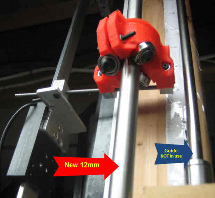
Cut another 36" section out of 3 72" rods I have
Call this on "Rod C"
Mounted it in test set up
Also rigged up guide rod (8mm) and guide (8mm linear bearing)
NOT in use in this test
Motor is held down a bit better
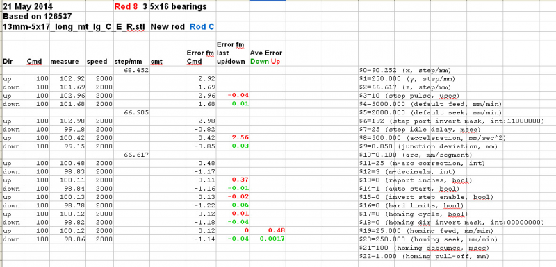
Here's some data
Threadless Ball Screw, 10mm travel pr. rev 139425 mod for 12mm rod printing now
Threadless Leadscrew Olympics continue

|
Re: Threadless Leadscrew New rod May 21, 2014 08:12PM |
Registered: 10 years ago Posts: 1,381 |
Your down values look really good, I wonder why the up values are so different.
Maybe some error is coming from a change of direction, and the test equipment. Velocity, acceleration, jerk, maybe one of these messing up the difference in magnitude of the up, and down values?
What does Error from CMD stand for?
I don't understand all the values that you are recording, provide a definition of what your are collecting.
Not fully understanding your test method, I would like to see your test method modified. Record the difference from the expected value. Maybe some one else will come up with a better method that will help identify things that can be improved.
From zero, advance to 100 mm, and record the result.
From 100, advance to 200 mm, and record the result.
From 200, retract to 100 mm, and record the result.
From 100, retract to zero mm, and record the result.
Keep all stepper motor parameters constant until the system starts to improve.
|
Re: Threadless Leadscrew New rod May 21, 2014 08:55PM |
Registered: 11 years ago Posts: 1,049 |
What does Error from CMD stand for?
DRO measurement - Commanded from UGS
ex 102.08 - 100 error 2.08
With steps/mm set in GRBL a command of 100 should produce 100mm of travel
I average 2 up and 2 down movements and correct steps/mm.
You can see Velocity, acceleration, jerk
in GRBL parameters (right on spreadsheet)
Test method:
zero DRO
command via Universal Gcode sender
Read record DRO measurement.
repeat
Generally do :
zero DRO
up 100
record DRO
zero DRO
down 100
record DRO
??????

|
Re: Threadless Leadscrew New rod May 21, 2014 10:56PM |
Registered: 10 years ago Posts: 1,381 |
Tks.
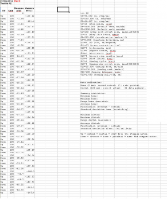
I would like to see you set the home position to zero and not change it until 31 data points are collected, values collected categorized by their location (proximal, distal), and fix all variables, such as speed, step/mm, velocity, acceleration, jerk, etc. How about posting a summary statistics like this:
Data collection:
Home (0 mm): record actual: (31 data points).
Distal (100 mm): record actual: (31 data points).
Summary statistics:
Minimum home:
Maximum home:
Range home (max-min):
Average home:
Fluctuation (average - actual):
Standard deviation home (volatility):
Minimum distal:
Maximum distal:
Range distal (max-min):
Average distal:
Fluctuation (average - actual):
Standard deviation distal (volatility):
Up = extend = distal = away from the stepper motor.
Down = retract = home = proximal = near the stepper motor.
|
Re: Threadless Leadscrew ??? May 22, 2014 12:47AM |
Registered: 11 years ago Posts: 1,049 |
|
Re: Threadless Leadscrew ??? May 22, 2014 01:06AM |
Registered: 10 years ago Posts: 1,381 |
Sorry, only registered users may post in this forum.
