Threadless Leadscrew ???
Posted by cozmicray
|
Re: Threadless Leadscrew ??? May 22, 2014 03:56AM |
Registered: 11 years ago Posts: 251 |
I don't see this as a feasible positioning method on a reprap.
It's entirely friction based - therefore there will be small errors. This error will be have a component due to:
1) The acceleration
2) The speed
3) Distance
Since we cannot guarantee that the path taken in the +ve direction equals the path in the - ve direction, although the net distance is zero we cannot be sure that the speeds/accelerations are the same in both directions. Therefore the error around a loop does not sum to zero.
Then add on a random element of error.
If we only print parts that are symmetrical in x&y, then a quick "order of magnitude" back of envelope calculation using random walk gives:
Acceptable mean error in a single move if re-homing every layer = 0.001mm
Acceptable mean error in a move if no homing during a print = 0.0001mm
I don't think this repeatability can be achieved. Maybe this could work on Z where there are limited movements.
However - I think the idea of using a drill bit as a leadscrew is excellent! Long masonary drill bits are available for a few pounds.
Edited 3 time(s). Last edit at 05/22/2014 07:07AM by konwiddak.
|
Re: Threadless Leadscrew ??? May 22, 2014 07:01AM |
Registered: 11 years ago Posts: 251 |
www.zero-max.com
Positioning Accuracy
The Roh’lix is a friction drive device and as a result, will show an accumulated error that is, in general, up to 0.002 inches per shaft revolution. Where greater accuracy is required, linear encoders can be used to indicate position.
Positioning Accuracy
The Roh’lix is a friction drive device and as a result, will show an accumulated error that is, in general, up to 0.002 inches per shaft revolution. Where greater accuracy is required, linear encoders can be used to indicate position.
|
Re: Threadless Leadscrew ??? May 22, 2014 11:39AM |
Registered: 10 years ago Posts: 1,381 |
@konwiddak:
It's been suggested to periodically re-home to correct for cumulative errors. If we can print a bearing retainer with a repeatable, and forecastable error, we can then calculate when to recalibrate our machine. In addition it may never be as accurate as the current systems being employed are, but it might be good enough for some individuals, and applications.
Threadless Ball Screw Bench Test
[www.youtube.com]
This setup is off 0.23 mm.
|
Re: Threadless Leadscrew ??? May 23, 2014 04:13AM |
Registered: 11 years ago Posts: 251 |
Don't get me wrong, I think this is a great idea, but I'm still quite dubious about its integration into a reprap.
One way to potentially increase accuracy is using bearings with an internal radius larger than the bar diameter and running the inside of the bearing along the rail. This will result in a more favourable line contact rather than a point.
Edited 1 time(s). Last edit at 05/23/2014 12:51PM by konwiddak.
|
Re: Threadless Leadscrew more data May 23, 2014 10:35PM |
Registered: 11 years ago Posts: 1,049 |
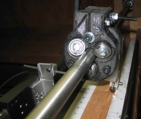
Made up thingaverse 139425 modded for 12mm rod six 5 x16 bearings
Black 11&12
two 3 bearing riders spaced by 8mm mount
Same test set up
Here is the data
(also have data on only Black 11 on the test rack)

Black 11&12
two 3 bearing riders spaced by 8mm mount
Same test set up
Here is the data
(also have data on only Black 11 on the test rack)

|
Re: Threadless Leadscrew ??? May 27, 2014 09:23AM |
Registered: 11 years ago Posts: 72 |
I have made some test a long time ago, but disasambled it all. Found that you need to support the bearings on both sides, so it stay completly level to the rod.
Se my album for inspiration. Don't ask for stl or futher test, I don't have the time, but just wanted to share if someone could use it.
[plus.google.com]
Jesper
Edited 1 time(s). Last edit at 05/27/2014 09:24AM by Kenzu.
Se my album for inspiration. Don't ask for stl or futher test, I don't have the time, but just wanted to share if someone could use it.
[plus.google.com]
Jesper
Edited 1 time(s). Last edit at 05/27/2014 09:24AM by Kenzu.
|
Re: Threadless Leadscrew ??? May 27, 2014 12:16PM |
Registered: 11 years ago Posts: 1,049 |
"need to support the bearings on both sides, so it stay completly level to the rod."
I don't understand
On my test set up there is a flange bearing on each end of the 12mm rod
the bearings are held by the flange which is held by two screws
The bearings hold the rod parallel to the base.
I can't see how a bearing point can be leveled to a rod.
My test set is setup at near vertical ( ~80 deg)
Your set up? Why is guide rod driven by motor?
I do not use a guide rail

|
Re: Threadless Leadscrew ??? May 27, 2014 04:19PM |
Registered: 11 years ago Posts: 15 |
|
Re: Threadless Leadscrew ??? May 28, 2014 01:26AM |
Registered: 9 years ago Posts: 210 |
Ok first thanks for testing this Cozmicray, I have a couple of (stupid) ideas:
Why are steel rollers used? Wouldn't a material with higher friction be better? Why not use rubber wheels that have a tilted outer rim to stick to the outer wall of the rod? There probably is a reason but I wonder, a slanted rubbery surface on the wheels could reduce slippage and reduce the tension required.
With the (really dirt cheap) standard threaded lead screws, you could maybe have a special wheel to artificially increase the lead of the screw. If you would put wheels with longitudinal trapezoid threads in the wheel surface you would have something similar to a ball screw (wheel screw? ) so you would reduce friction compared to a trapezoid acme screw. But the same lead.
Now if those trapezoidal threads on the wheel would be rotated so that turning the wheel would switch to the next grove, this could create a stepping up movement and increase the speed of a standard cheap threaded rod. So you might have the advantage of an expensive ball screw. This would only work of course if you can 3D print these threads and they don't wear out.
EDIT: Upon further thinking about this, it just wouldn't work.
Long drills look interesting, I can buy 600mm long drills for something like 8€. They ought to be straight. But the unknown and non standardized lead and precision is probably going to be a problem.
Edited 1 time(s). Last edit at 05/28/2014 05:41AM by Dejay.
Why are steel rollers used? Wouldn't a material with higher friction be better? Why not use rubber wheels that have a tilted outer rim to stick to the outer wall of the rod? There probably is a reason but I wonder, a slanted rubbery surface on the wheels could reduce slippage and reduce the tension required.
 ) so you would reduce friction compared to a trapezoid acme screw. But the same lead.
Now if those trapezoidal threads on the wheel would be rotated so that turning the wheel would switch to the next grove, this could create a stepping up movement and increase the speed of a standard cheap threaded rod. So you might have the advantage of an expensive ball screw. This would only work of course if you can 3D print these threads and they don't wear out.
EDIT: Upon further thinking about this, it just wouldn't work.
Long drills look interesting, I can buy 600mm long drills for something like 8€. They ought to be straight. But the unknown and non standardized lead and precision is probably going to be a problem.
Edited 1 time(s). Last edit at 05/28/2014 05:41AM by Dejay.
|
Re: Threadless Leadscrew ??? May 28, 2014 11:47AM |
Registered: 10 years ago Posts: 20 |
@Dejay
A rubber roller would be good if the rubber coating was really thin. If it gets to thick it will deform and act like a string in the linkage which is not desirable. If it was really thin and the pre-load was relatively high then the it should work really well.
Again drill rods and other rods with THREADS are a side topic from this conversation since this is about threadLESS leadscrews. All though they merit discussion it is another thread.
@cozmicray
With the black rider are all of the bearings turning?
Also with the new rod is it running true IE not wobbling?
If the angle of each bearing is not identical then they could skip around or contact at different times which could cause it to move erratically (All things are relative). All of these factors could lead to seemingly random variation in the measured displacement.
I am thinking that some position feedback may be in order very soon then it will not matter what the exact accuracy is since you would just drive it in a PID loop until you got to the desired position. I am not suggesting a DRO on each axis that would be way too expensive. I have another idea that I have been kicking around that I hope to work on in the near future. I will post about it soon.
|
Re: Threadless Leadscrew ??? May 28, 2014 11:47AM |
Registered: 10 years ago Posts: 20 |
|
Re: Threadless Leadscrew ??? May 28, 2014 01:34PM |
Registered: 9 years ago Posts: 210 |
Quote
dexterm2003
A rubber roller would be good if the rubber coating was really thin. If it gets to thick it will deform and act like a string in the linkage which is not desirable. If it was really thin and the pre-load was relatively high then the it should work really well.
Shouldn't the preload required for rubberized wheels be lower that for steel wheels? Also you could have the wheel not tilted the way it is and just straight on the steel rod. I was thinking about using some kind of mini wheel for RC or rollerblades that already has bearings, but maybe there is a kind of "rubber paint" that you could just paint the bearings with. It would have to be pretty strong material and fused to the wheel and thin as not to get stripped away.
I wish my printer kit would arrive already so I could try some of this stuff

Edited 1 time(s). Last edit at 05/28/2014 01:34PM by Dejay.
|
Re: Threadless Leadscrew ??? May 28, 2014 03:00PM |
Registered: 11 years ago Posts: 1,049 |
Perhaps the outer surface of bearing could be coated
with an abrasive, corundum or diamonds.
Abrasive may have to be embeded.
Studded snow tires on bearings?
Four or five travels up and down rod
would shread threads into rod.
A self making leadscrew?
Perhaps knurled out surface?
I am beginning to think that common bearings will NEVER
be able to do this.
Custom bearing races with angled surfaces necessary
very expensive --- easier / cheaper to buy leadscrew.
|
Re: Threadless Leadscrew ??? May 28, 2014 05:25PM |
Registered: 10 years ago Posts: 979 |
It seems to me that in the best case scenario you will be homing a lot. To me the only way forward if you want accuracy is to close the loop.
ConceptFORGE
Wally, GUS Simpson, LISA Simpson, THOR Simpson, Sextupteron, CoreXZ
ConceptFORGE
Wally, GUS Simpson, LISA Simpson, THOR Simpson, Sextupteron, CoreXZ
|
Re: Threadless Leadscrew ??? May 28, 2014 06:15PM |
Registered: 11 years ago Posts: 1,049 |
Black 11-12 rider test video
it may look horizontal but rig is near vertical (~80deg)
mirror above trys to show back bearings spinning.
Guide rod NOT being used.
Data for this setup / rider test set up in my message of May 23, 2014 10:35PM
[www.youtube.com]
Have phun analyzing it!!

it may look horizontal but rig is near vertical (~80deg)
mirror above trys to show back bearings spinning.
Guide rod NOT being used.
Data for this setup / rider test set up in my message of May 23, 2014 10:35PM
[www.youtube.com]
Have phun analyzing it!!

|
Re: Threadless Leadscrew ??? May 28, 2014 06:45PM |
Registered: 10 years ago Posts: 20 |
I looked at the data and if you chart all of the up values from each run on one line and all of the downs on one line it looks like it is fairly repeatable. The accuracy is off but repeatability is good. The shift between the mean up and down values could be attributed to some slop (play) in the measuring setup. The values feel fairly repeatable though which is really good +/- 0.01 mm is pretty dang good. The next thing to work on would be accuracy which has more to do with play in the experimental setup.
Without moving the carriage can you replicate the 0.4 mm deviation in the DRO by just trying to move it by hand without driving the stepper. If so that would explain your 0.4 mm deviation that you see in the CMD-100 data
Let me know how that goes.
Thanks,
Michael
Without moving the carriage can you replicate the 0.4 mm deviation in the DRO by just trying to move it by hand without driving the stepper. If so that would explain your 0.4 mm deviation that you see in the CMD-100 data
Let me know how that goes.
Thanks,
Michael
|
Re: Threadless Leadscrew ??? May 28, 2014 08:42PM |
Registered: 11 years ago Posts: 1,049 |
Just did a test
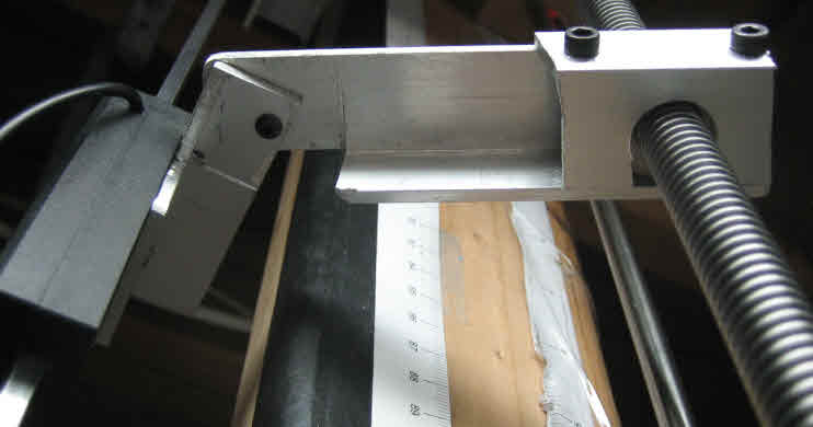
at point where DRO connects to connecting rod over to rider:
With my finger:
Read out on DRO:
push up -0.03mm
push down 0.08mm
with digital scale (digital readout of pull on guage):
46 oz down 0.000 mm
48 oz up -0.005 mm
don't think DRO connection has much slop
I should try pulling at the 12mm rod to see if 2 inch from
rod interface with rider?
I have ordered up a 36" leadscrew to put in place as a control
don't know when I'll get it and may have to change set up slightly 12mm v 1/2 inch

|
Re: Threadless Leadscrew ??? May 29, 2014 05:11PM |
Registered: 10 years ago Posts: 20 |
I would agree try repeating the test at the 12 mm rod.
Also using the leadscrew as a control is a very good practice since that is what we are really trying to find out. Is a threadless leadscrew more and less accurate than a true leadscrew.
Keep up the good work and let me know the results!
Also using the leadscrew as a control is a very good practice since that is what we are really trying to find out. Is a threadless leadscrew more and less accurate than a true leadscrew.
Keep up the good work and let me know the results!
|
Re: Threaded Leadscrew ??? control June 02, 2014 07:28PM |
Registered: 11 years ago Posts: 1,049 |
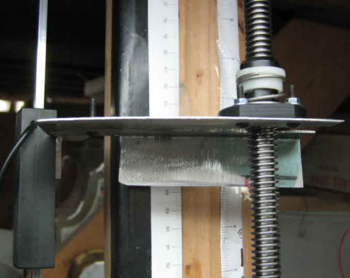
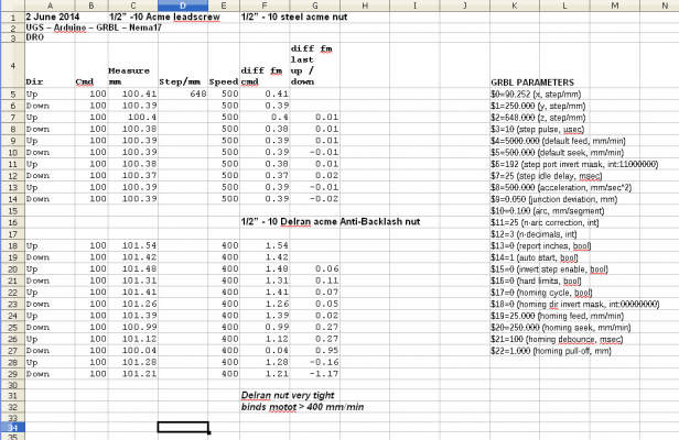
Threaded Leadscrew tests
This is suppose to be a CONTROL on my system
36" 1/2" - 10 steel acme leadscrew
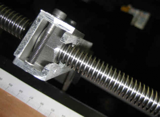
Steel 1/2" acme nut
Delran 1/2" anti-backlash nut
1/2" bearings supporting leadscrew
Same Nema 17 motor driven with 24v
UGS - Arduino - GRBL - Neam 17 motor - leadscrew
Rider with 1/2" steel acme nut connection to DRO
Rider with 1/2" Delran anti-backlash nut connection to DRO
The Data

|
Re: Threadless Leadscrew ??? June 05, 2014 03:19AM |
Registered: 9 years ago Posts: 1 |
that's a cool idea , but with the bearing face at around 65 rc and if the shaft is hardened then
the surfaces are slippery on each other, with the servo's moving the plate back and forth.
as the plate gets heavier with your project then I think the bearing might slip on the shaft on the X and Y
, it may not slip on rotation axis , with threads it can't do that with the take up nut on the acme thread
takes up the backlash
|
Re: Threadless Leadscrew ??? June 05, 2014 03:53AM |
Registered: 10 years ago Posts: 1,381 |
|
Re: Threadless Leadscrew ??? June 09, 2014 04:43AM |
Registered: 10 years ago Posts: 1,381 |
|
Re: Threaded Leadscrew ??? control June 23, 2014 08:44PM |
Registered: 11 years ago Posts: 1,049 |
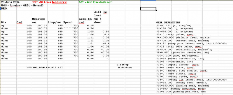
Some more data on threaded leadscrew control
1/2"-10 leadscrew with plastic anti-backlash nut
NEMA 23 motor driving screw 24V
DATA

1/2"-10 leadscrew with plastic anti-backlash nut
NEMA 23 motor driving screw 24V
DATA

|
Re: Threadless Leadscrew ??? June 28, 2014 04:44AM |
Registered: 10 years ago Posts: 1,381 |
Ball bearing riding in a grove. Looks to me like the bearing has square edges, while the screw has a round profile.
Winners Technology -New type of ball screw, bearing screw
[www.youtube.com]
Winners Technology -New type of ball screw, bearing screw
[www.youtube.com]
Sorry, only registered users may post in this forum.
