Threadless Leadscrew ???
Posted by cozmicray
|
Re: Threadless Leadscrew ??? April 07, 2014 04:52PM |
Registered: 11 years ago Posts: 1,049 |
|
Re: Threadless Leadscrew 4 bearing ?? April 10, 2014 06:48PM |
Registered: 11 years ago Posts: 1,049 |
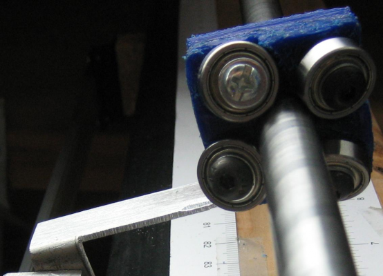
4 bearing rider
customized thing:124706 16 x 5 bearings
Seems loose but doesn't seem to slip
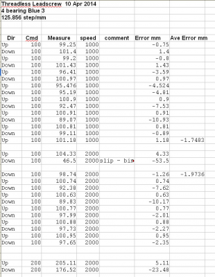
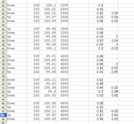
Some data ???? lots of error ????
Need to find a Threadless Leadscrew anonymous group?

customized thing:124706 16 x 5 bearings
Seems loose but doesn't seem to slip
Some data ???? lots of error ????
Need to find a Threadless Leadscrew anonymous group?

|
Re: Threadless Leadscrew 4 bearing ?? April 10, 2014 07:36PM |
Registered: 10 years ago Posts: 1,381 |
|
Re: Threadless Leadscrew 4 bearing ?? April 13, 2014 06:41PM |
Registered: 10 years ago Posts: 1,381 |
Threadless ball screw bench test for position deviation.
[www.thingiverse.com]
The maximum carriage speed was F24000 -> 400 mm/sec.
In a short testing, the threadless ball screw shows big deviation.
[www.thingiverse.com]
The maximum carriage speed was F24000 -> 400 mm/sec.
In a short testing, the threadless ball screw shows big deviation.
|
Re: Threadless Leadscrew ??? April 24, 2014 06:08PM |
Registered: 11 years ago Posts: 1,049 |
24 April 2014 testing
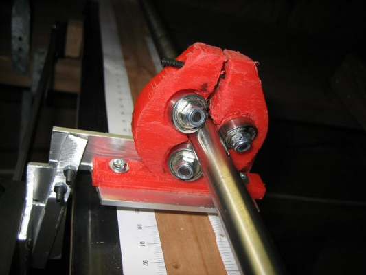
Red3 16x5 ----- threadless Leadscrew rider
Thingiverse thing:125529 customized for 16mm OD x 5mm ID bearings
compression is very touchy ? got to measure it somehow ?
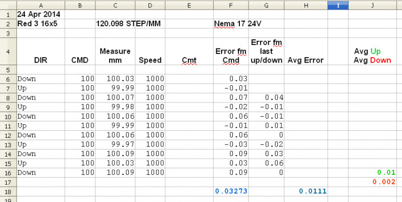
Data with my standard set up 24v supply NEMA17 GRBL Arduino UGS107 12" DRO
Data or red 3 16x5 rider at higher speeds

Red3 16x5 ----- threadless Leadscrew rider
Thingiverse thing:125529 customized for 16mm OD x 5mm ID bearings
compression is very touchy ? got to measure it somehow ?
Data with my standard set up 24v supply NEMA17 GRBL Arduino UGS107 12" DRO
Data or red 3 16x5 rider at higher speeds

|
Re: Threadless Leadscrew ??? April 24, 2014 10:44PM |
Registered: 10 years ago Posts: 1,381 |
It appears you're doing much better.
So I can better understand, can you provide a written summary of your results with the units denoted.
I noticed a potential source of error, and possibly you have accounted for thi. Using only one guide rod, you need to make sure that the bearing housing is rotated to the same side (against a stop), or the measurement will be off from the housing freely rotating.
|
Re: Threadless Leadscrew ??? April 24, 2014 10:45PM |
Registered: 10 years ago Posts: 979 |
These numbers are not so bad. I wonder what would happen if you double them up like you would want to do for LISA. I also wonder what this would look like if you had a low acceleration value and a zero jerk value and you went back and forth 1000 times. I would consider any error value less than 250 microns for that test to be success.
On a side note, I used some statistics to extrapolate what the error might look like for 1000 back and forths based on your first run. I came up with a projected standard deviation of 640 microns. That means 66% of the time the error will be less than +/-640 microns after 1000 round trips. I actually think that is getting close to acceptable. I think doubling the bearing up and a few other tweaks might get us there.
Note: any statistics based on 10 numbers is suspect so let's not get too excited.
ConceptFORGE
Wally, GUS Simpson, LISA Simpson, THOR Simpson, Sextupteron, CoreXZ
|
Re: Threadless Leadscrew ??? April 24, 2014 11:46PM |
Registered: 11 years ago Posts: 1,049 |
All my measurements are in mm (millimeter) DRO measues to XX.xx mm.
I zero the DRO,
command via UGS to do +Z 100 units (at default speed or commanded speed)
read / record DRO reading
I zero the DRO,
command via UGS to do -Z 100 units (at default speed or commanded speed)
read / record DRO reading.
In some of my tests I moved to different 100mm places on rod
and that is noted in comments.
Red 3 16x5 has a thicker/stiffer plate on bottom of rider
and plate attached to DRO is thicker and stiffer.
The connection to the DRO prevents rider rotation.
If rider is free it will rotate until it hits the board under rod.
I noticed when I put Red 3 rider on that two of the bearings were not rotating
so I reworked bearing mounts and added washers between bearings and PLA.
I have black marks on outer race of all bearing to show rotation.
I also notice compression by bolt on top
does not provide even pressure on all bearings.
The ultimate rider may need independent tensioning on each bearing
but that is individual tension and angle on each bearing set.
Have to work on that design.
I have been looking into reading DRO into computer
for maybe an automated logger.
Also thinking about putting encoder on rod to see
commands equal to what rod / motor is doing.
Also I will get some more bearings 16x5
and making up another rider and put them back to back on same rod.
Maybe after 100,000 measurements under .01mm error I can rest?
Might be easier to just laser measure where the hot end really is?

A2
It appears you're doing much better.
So I can better understand, can you provide a written summary of your results with the units denoted.
I noticed a potential source of error, and possibly you have accounted for thi. Using only one guide rod, you need to make sure that the bearing housing is rotated to the same side (against a stop), or the measurement will be off from the housing freely rotating.
I zero the DRO,
command via UGS to do +Z 100 units (at default speed or commanded speed)
read / record DRO reading
I zero the DRO,
command via UGS to do -Z 100 units (at default speed or commanded speed)
read / record DRO reading.
In some of my tests I moved to different 100mm places on rod
and that is noted in comments.
Red 3 16x5 has a thicker/stiffer plate on bottom of rider
and plate attached to DRO is thicker and stiffer.
The connection to the DRO prevents rider rotation.
If rider is free it will rotate until it hits the board under rod.
I noticed when I put Red 3 rider on that two of the bearings were not rotating
so I reworked bearing mounts and added washers between bearings and PLA.
I have black marks on outer race of all bearing to show rotation.
I also notice compression by bolt on top
does not provide even pressure on all bearings.
The ultimate rider may need independent tensioning on each bearing
but that is individual tension and angle on each bearing set.
Have to work on that design.
I have been looking into reading DRO into computer
for maybe an automated logger.
Also thinking about putting encoder on rod to see
commands equal to what rod / motor is doing.
Also I will get some more bearings 16x5
and making up another rider and put them back to back on same rod.
Maybe after 100,000 measurements under .01mm error I can rest?
Might be easier to just laser measure where the hot end really is?

A2
It appears you're doing much better.
So I can better understand, can you provide a written summary of your results with the units denoted.
I noticed a potential source of error, and possibly you have accounted for thi. Using only one guide rod, you need to make sure that the bearing housing is rotated to the same side (against a stop), or the measurement will be off from the housing freely rotating.
|
Re: Threadless Leadscrew ??? April 24, 2014 11:52PM |
Registered: 11 years ago Posts: 1,049 |
|
Re: Threadless Leadscrew ??? April 25, 2014 12:07AM |
Registered: 10 years ago Posts: 979 |
@cozmicray: I am not sure about acceleration. I just tune it until I get to the edge of missing steps and then half it. I keep jerk really low 20mm/s or something like this.
My theory is that your speed doesn't mess with your accuracy. I think it is the starting and stopping.
So it looks like after you double the bearing we could print a certain linear distance, rehome, and repeat. If you rehome while you are doing infill then no one would know. (LISA homing is not trivial so there are two fronts to this problem. If you used this for a Cartesian printer then it would be pretty easy to rehome but we still have to interject some homes in the gcode. Shouldn't be too hard.)
ConceptFORGE
Wally, GUS Simpson, LISA Simpson, THOR Simpson, Sextupteron, CoreXZ
|
Re: Threadless Leadscrew ??? April 25, 2014 12:35AM |
Registered: 10 years ago Posts: 1,381 |
Quote
cozmicray
I noticed when I put Red 3 rider on that two of the bearings were not rotating
so I reworked bearing mounts and added washers between bearings and PLA.
I have black marks on outer race of all bearing to show rotation.
That's a good observation, do you attribute correcting this it to the improved precision?
Quote
cozmicray
I also notice compression by bolt on top
does not provide even pressure on all bearings.
The ultimate rider may need independent tensioning on each bearing
but that is individual tension and angle on each bearing set.
Have to work on that design.
Another good observation. If you need help designing individual tensioning let me know.
Quote
cozmicray
Might be easier to just laser measure where the hot end really is?
You gave me an idea with your comment.
After n-steps, n-layers, n-time, etc., run a homing routine to reset it, then resume printing.
|
Re: Threadless Leadscrew Duel Rider April 28, 2014 04:25PM |
Registered: 11 years ago Posts: 1,049 |
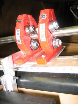
Double Rider on 12mm rod a 16x5 bearing Rider and 15x6 bearing rider
I didn't have 12 of the same bearings
Riders held together with plate on bottom of Riders
Red 3 16x5 Red 4 15x6
All 12 bearings never spinning at same time
One or two bearings not rotating during rod rotation.
Compression problem?
Top moving together and farther apart?
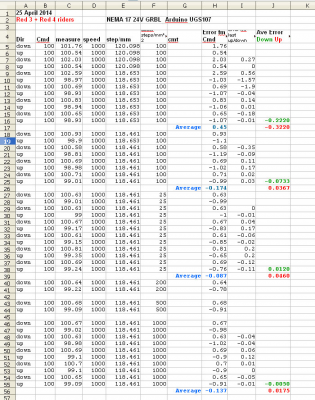
Data for Duel Rider testing

I didn't have 12 of the same bearings
Riders held together with plate on bottom of Riders
Red 3 16x5 Red 4 15x6
All 12 bearings never spinning at same time
One or two bearings not rotating during rod rotation.
Compression problem?
Top moving together and farther apart?
Data for Duel Rider testing

|
Re: Threadless Leadscrew Duel Rider April 28, 2014 04:28PM |
Registered: 11 years ago Posts: 1,049 |
GRBL Paramters for above Red 3- 4 test
Red 3 16x5 Red 4 15x6 25 April 2014 4:15pm
GRBL Parameters
$0=90.252 (x, step/mm)
$1=250.000 (y, step/mm)
$2=118.461 (z, step/mm)
$3=10 (step pulse, usec)
$4=5000.000 (default feed, mm/min)
$5=1000.000 (default seek, mm/min)
$6=192 (step port invert mask, int:11000000)
$7=25 (step idle delay, msec)
$8=1000.000 (acceleration, mm/sec^2)
$9=0.050 (junction deviation, mm)
$10=0.100 (arc, mm/segment)
$11=25 (n-arc correction, int)
$12=3 (n-decimals, int)
$13=0 (report inches, bool)
$14=1 (auto start, bool)
$15=0 (invert step enable, bool)
$16=0 (hard limits, bool)
$17=0 (homing cycle, bool)
$18=0 (homing dir invert mask, int:00000000)
$19=25.000 (homing feed, mm/min)
$20=250.000 (homing seek, mm/min)
$21=100 (homing debounce, msec)
$22=1.000 (homing pull-off, mm)
|
Re: Threadless Leadscrew New Design Rider April 28, 2014 04:52PM |
Registered: 11 years ago Posts: 1,049 |
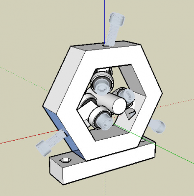
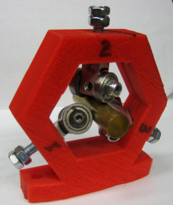
New Design Rider (preliminary)
independent compression to rod of bearings
A friend (a sketchup xspurt) and I workin it.
Not sure if it will hold pitch and bearing compression to rod
3, two bearing (625) bogies at angle in sliding slots
M6 bolts (or maybe springs) provide compression between hex and rod
Lots of things to think about and test?
??Is it worth it ??
Hex is designed to be printable??

|
Re: Threadless Leadscrew Duel Rider April 28, 2014 07:06PM |
Registered: 10 years ago Posts: 979 |
I wouldn't get too worked up about those numbers (yet) until you can figure out why one of the bearings doesn't turn. They should all turn freely and easily. Also, I would want the two bearings to be rigidly attached to each other. One last thing, are the pitches exactly the same? I think it is essential that both carriages be identical, printed on the same machine, and with the same bearings. I have seen these designed so that you can bolt two of these together back to back. In a month or so, I will get some time to do some testing myself. This is one of those things that it is just dripping with potential so I have to see it myself before I write it off.
I thought you only had 3 bearings/ carriage earlier. With the 6 per carriage I would not expect there to be any improvement with two carriages.
It is sad that it seems like this might be a no go. I don't know if I have said it in this thread or not but even the commercial versions doesn't claim repeat-ability. Fix the tension issue and if that still fails then we can call this dead.
I don't know if your new design will be rigid enough. I will try to do a mockup.
ConceptFORGE
Wally, GUS Simpson, LISA Simpson, THOR Simpson, Sextupteron, CoreXZ
|
Re: Threadless Leadscrew Duel Rider April 28, 2014 08:06PM |
Registered: 10 years ago Posts: 1,381 |
The New Design Rider (preliminary) is interesting but the post supporting the bearings are lacking support.
Take the original design, and add a bearing on the opposite side of the retainer.
To increase the rigidity, increase the spacing between the bearings by at least 3X.
Ex. if the bolt Dia is 8 mm you want >8 mm x 3 = 24 mm spacing between the washers that are located on either side of the bearings.
Idea to increase the bearing grip.
Using a steel hose clamp, wrap the hose clamp around the protruding ends of the bolt and cinch it down.
You might need to crease the metal band to aid in holding it in position while you tighten it.
With two hose clamps on either side of a gang of 6 bearings you should be able to increase the clamping force evenly.
To improve the accuracy of the retainer, eliminate the original clamp design.
|
Re: Threadless Leadscrew ??? April 28, 2014 08:58PM |
Registered: 11 years ago Posts: 89 |
|
Re: Threadless Leadscrew ??? April 28, 2014 09:04PM |
Registered: 10 years ago Posts: 1,381 |
|
Re: Threadless Leadscrew ??? April 28, 2014 09:05PM |
Registered: 10 years ago Posts: 979 |
@SheldonE: That is the solution I would like to target.
@Cozmicray: 1000mm/s/s for acceleration sounds like a bit much. I would drop it to 100mm/s/s at least for testing. I would calculate what is the highest acceleration the steppers could actually generate and then divide by a very healthy factor of safety. If you are too lazy to do the math just set it really low for testing knowing that you might be able to push it more in the future.
ConceptFORGE
Wally, GUS Simpson, LISA Simpson, THOR Simpson, Sextupteron, CoreXZ
|
Re: Threadless Leadscrew ??? April 28, 2014 09:07PM |
Registered: 10 years ago Posts: 1,381 |
|
Re: Threadless Leadscrew ??? April 28, 2014 09:13PM |
Registered: 11 years ago Posts: 89 |
|
Re: Threadless Leadscrew ??? April 28, 2014 11:06PM |
Registered: 11 years ago Posts: 1,049 |
Sheldon
3 compression splits would make the rider fall apart, at least very wobbly?
I suppose 2 or three compression bolts between each split?
very hard to set compression
--This compression with slits is appling the compression the wrong way.
Independent compression to the rod is a must.
Each bolt could be tightened with torque wrench to spec the compression,
a known compression.
A2
Bearing spacing? Between the two bearings on each bogey?
Bearings on retainers?
Rectangular bearing holder fixed in slot in hexto hold angle
--- I suppose I could put rectangular titanium tube in hex to take the ywist force
--- but it doesn't need to be carrier landing qualified?
Hex frame could be made of steel or titanium but I couldn't make it.
Not with rectangular slots in it.
I suppose I could weld steel rectangle tubes in plates then weld plates
together in triangle or hex?
But then I may have to suspend them from helium baloons to lighten them up.
This will go on a 3D printer NOT a heavy dudy tow truck?
This hose clamp around the unit is a joke right?
Providing radial force and side/rotation force.
Nick
speed, acceleration and jerk of Lisa would help with design?
Parameter settings got to be in software/ firmware code?

|
Re: Threadless Leadscrew ??? April 28, 2014 11:16PM |
Registered: 10 years ago Posts: 979 |
For testing I would suggest the following settings. Your error could be solely from skipped steps.
Acceleration: 100mm/s/s
Speed: 25mm/s
Jerk:0 mm/s
ConceptFORGE
Wally, GUS Simpson, LISA Simpson, THOR Simpson, Sextupteron, CoreXZ
Acceleration: 100mm/s/s
Speed: 25mm/s
Jerk:0 mm/s
ConceptFORGE
Wally, GUS Simpson, LISA Simpson, THOR Simpson, Sextupteron, CoreXZ
|
Re: Threadless Leadscrew ??? April 28, 2014 11:18PM |
Registered: 11 years ago Posts: 89 |
Quote
cozmicray
3 compression splits would make the rider fall apart, at least very wobbly?
I suppose 2 or three compression bolts between each split?
That's what I was thinking, rotate the design 60 degrees and have a split every 120 degrees. Have 2 compression bolts located as close to outer rim as possible, increase the width by 100% and ensure it's printed at 100% infill. That should be enough to ensure rigidity. I assume you have bearings on both sides on the rider...
I have no experience with designing printed parts (my i3 printer is almost complete) and I did some enginerring at the teriary level, so take my suggestions with that in mind.
|
Re: Threadless Leadscrew New Design nada May 01, 2014 08:22PM |
Registered: 11 years ago Posts: 1,049 |
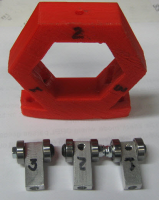
I don't think the design is going to work
This is by drawring set up, -- 16x5 bearings
Milled bogey tabs (holders) Aluminium
20mm length bogey tabs, 25mm didn't allow enough room
rectangular pockets a pain, not deep enough to provide support
and after cleaning them out -- not a good fit.
I cut down bogey tabs from 30, to 25 to 20 mm oops to short
but needs more support in outer hex pockets.
Compression bolts M6
In pixs 12mm brass tube stand in for 12mm steel rod
This is NOT a compact design
Angle of bogeys may be too much?
I'll redo Bogey tabs to see if I can get it to work
??How to hold angle, and provide travel for compression adjustment??
Got to re-examine whole design
Bogey Tabs at 30mm

|
Re: Threadless Leadscrew ??? May 07, 2014 05:02AM |
Registered: 11 years ago Posts: 251 |
|
Re: Threadless Leadscrew ??? May 12, 2014 09:42PM |
Registered: 10 years ago Posts: 20 |
@cozmicray First thanks for your work I am very interested in seeing threadless ball screws applied to 3d printing.
I agree with A2 about the wobble of the shaft. That can have a large effect on the repeatability of the measurements. It also looks like the shaft has some pitting (may just be dirt or debris).
I would suggest getting proper shafting.
Shafting
The other thing that I would suggest is use a control to test your experimental setup. Check the accuracy with a regular threaded rod and nut or an acme screw or some other leadscrew setup.
Have you tried to turn it by hand and see how smooth it turns? In order to be accurate and repeatable it should turn very smoothly. Any binding is a big problem and should be addressed.
I wonder if a 3d printer actually has the accuracy and repeatability in order to print an accurate threadless carraige?
Best of luck and keep up the good work!
|
Re: Threadless Leadscrew ??? May 14, 2014 12:59PM |
Registered: 11 years ago Posts: 1,049 |
dexterm2003
I don't know where the inaccuracy / unrepeatbility is coming from.
The control would be a Roton leadscrew used on LISA simpson
Which is expensive! $100 for screw $120 for nut???
I may try a 1/2" threaded rod?
Shaft wobble --- well I have the bearings to put extreme tension on shaft.
I don't think that is solution.
So this shaft is NOT good enough:
17-4 PH Stainless Steel Round Rod 12 mm
17-4 Precipitation Hardening (PH) Stainless Steel combines high strength with corrosion resistance. The alloy is also known as 630 Stainless. 17-4PH has approximately the same heat and corrosion resistance as the 304 alloy.
Material: Stainless Steel
Alloy: 17-4 Stainless
Shape: Round Rod
Diameter: 12mm
Condition: H900
Finish: Turned, Ground and Polished
Hardness: RC 45-47
Notes: Tolerances: Diameter: (+0/-.0005) | Length (+/- 1/8")
Smoothness depending on rider compression --- turns smoothly by hand
I want to test it as it would run in a printer -- not by hand?
PLA rider body?
Bolts holding bearings are tight, no noticeable wobble in mount,
angle of holes set by CAM and print.
There is no other guide to stop rotation except the DRO connection.
So you think if the rider were milled out of metal it would solve the problem?
Other designs or design changes in rider would be helpfull
Other test procedures with my test set up?
Crowned / angled bearings? Digging into rod, smoothly rolliing?
Can you do dynamic CAD to show action, contact
I am about to join a 12 step program for my TLS addiction
Thanks for comments
Took Edison a lot of time for each breakthru?

|
Re: Threadless Leadscrew ??? May 14, 2014 02:35PM |
Registered: 10 years ago Posts: 1,381 |
Quote
cozmicray
So you think if the rider were milled out of metal it would solve the problem?
I reviewed a Threadless lead screw (~24 yrs ago) that had an aluminum housing to locate/retain the bearings, on a couple of different metal rods, one being a ground 316 SS rod.
It was jerky, and locked up due to the soft metal. I couldn't get the preload set properly.
A Threadless lead screw requires a ground, and harden shaft. I think as mentioned a few times before, it will also require a periodic reset/homing.
|
Re: Threadless Leadscrew ??? May 14, 2014 04:45PM |
Registered: 10 years ago Posts: 20 |
I don't think that tension is enough to eliminate shaft wobble. The video makes it look like the shaft is just plain bent or bowed.
316 SS is (as A2 said) soft. The recommended hardness is RC 58. for most threadless ball screw manufactures. The shafts that I sent you a like to are in the $25-50 range depending on size and length.
Yes a machined metal one would be much more accurate than a printed one. You mentioned that some of the roller don't turn I can only think of two reasons that would occur. One is that the roller is binding and can't turn. Second that the part is warpped and the roller is not even contacting the surface of the rod so that it can turn.
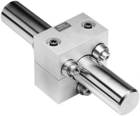
This is what one manufacturers threadless ballscrew looks like.
The manufacture has CAD of their design you might be able to print a plastic version fairly easily.
The whole reason I said to turn it by hand is to check for binding in the setup or if there were any irregularities in how it turns. It is much easier to feel for these than it is to measure them.
One thing to test would be a static load test to see how much thrust load your carrier can handle before it slips. The metal version above only has a thrust rating of 133 newtons for the 12mm model. Good thrust capacity will be important to the functionality of the finished product also a high thrust load will only occur with a good carriage that has good contact with all of the rollers.
PLA is one of the lower strength filaments available and so it will easily break or deflect more than you might want. Not sure if you have a heated bed to make one out of ABS. The other option would be to try Taulman nylon which is the strongest that I have heard of but you have to print on either a sheet of nylon plastic or garolite either of which are available from McMaster-Carr.
As far as the crowned rollers that is a possibilty but I doubt that a plastic carriage could generate enough force to really take advantage of the crown.
Other designs you might try include:
http://www.thingiverse.com/thing:164118
http://www.thingiverse.com/thing:112718
These designs look much more stout and you might have better luck.
Keep of the good work!
Sorry, only registered users may post in this forum.
