Parallel-kinematics versus string-pod
Posted by VDX
|
Parallel-kinematics versus string-pod September 28, 2007 04:19AM |
Admin Registered: 16 years ago Posts: 13,884 |
... as with the tripod-structure from the thread "Magnetic joints and self-assembly..:" there could be constructed several 3-axis-systems with different approaches, here for example with wire-feeding over fixed rolls.
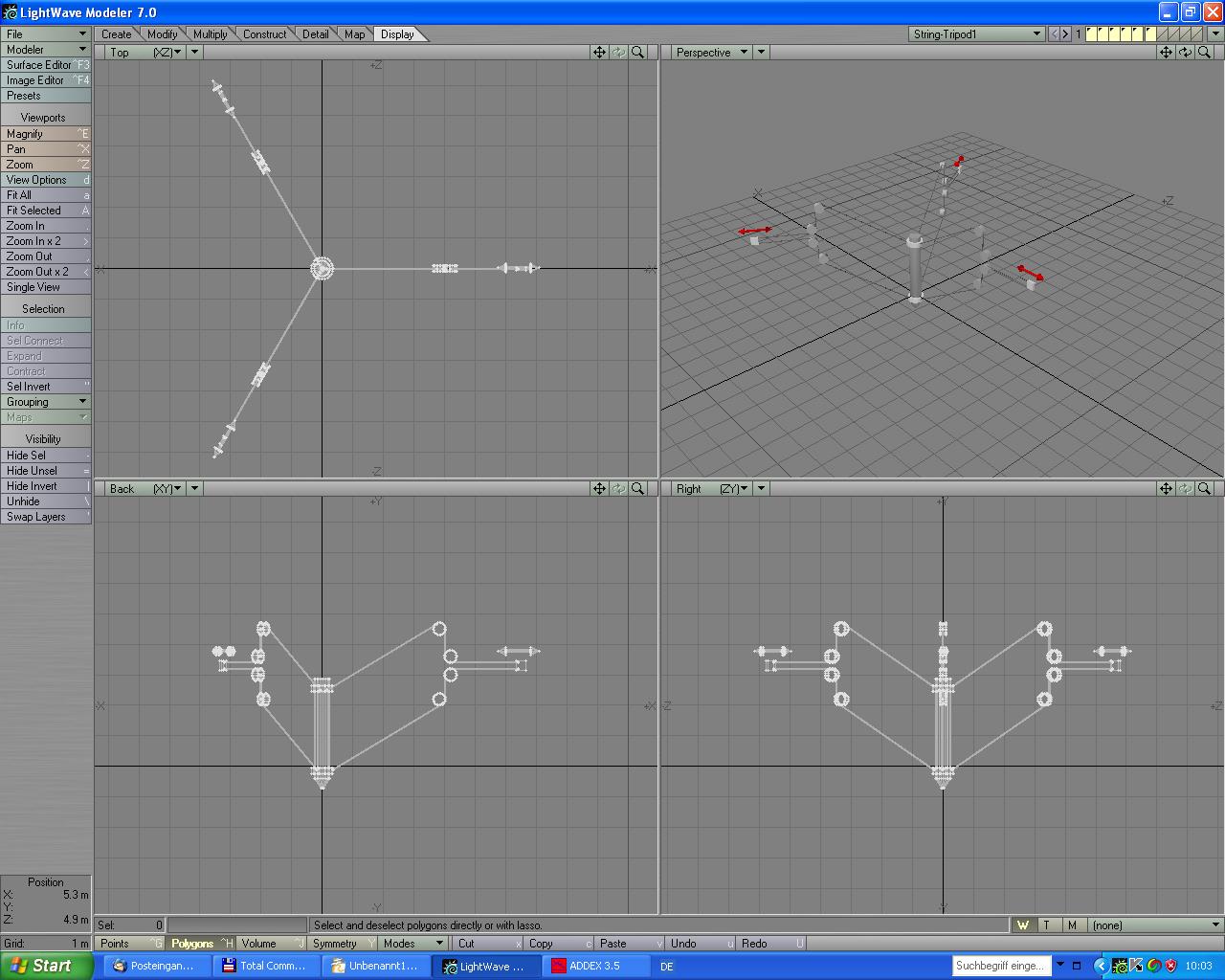
In the appending image i have a concept of a 'stringy tripod', which has only 3 gliders as moveable parts, which can be moved throug beltdrives or linear motors.
The toolhead can be moved in all directions through releasing and shortening of the wire-feeds, the rolls are fixed.
The weight of the toolhead (or added mass) should define a proper perpendicular position over the bed.
If someone wants more degrees of freedom or a more stable feeding, then i need 6 motors, but can move the toolhead in 6 axis too ...
Viktor
|
Re: Parallel-kinematics versus string-pod September 28, 2007 06:12PM |
Registered: 16 years ago Posts: 52 |
|
Re: Parallel-kinematics versus string-pod September 29, 2007 12:03AM |
Registered: 16 years ago Posts: 113 |
|
Re: Parallel-kinematics versus string-pod September 29, 2007 02:23PM |
Admin Registered: 16 years ago Posts: 13,884 |
... it's not so hard to make ONE straight edge - in [forums.reprap.org] all motors runs parallel, so for example say motor M1 and M2 are the both aligned motors in the back and motor M3 is the longer one in front ...
Then it should run in a similar mode:
X = M1 = M2 = M3 - if all tree motors run synchrone, X is straight X ...
Y = (M2 - M3)xAlpha1 + M3xBeta1, where Alpha and Beta are trigonometric calculated values, which planarize the movement of the toolhead
Z = (M2 - M3)xAlpha2 + M3xBeta2, dito for Z-movement
So with calculating of the Alphas and Betas and combining of the modes you can translate every cartesic coordinate or movement in tripod-action ...
I know, that some companies changed from cartesian to 3- and hexa-pod-milling because of higher dynamics and easier mechanical assemblies - especially in highspeed- and high-accuracy-microassembly-stations.
In some of our projects they are developing tripods for adjustment of optical systems and interferometers too ...
Viktor
|
Re: Parallel-kinematics versus string-pod November 09, 2007 02:27PM |
Admin Registered: 16 years ago Posts: 13,884 |
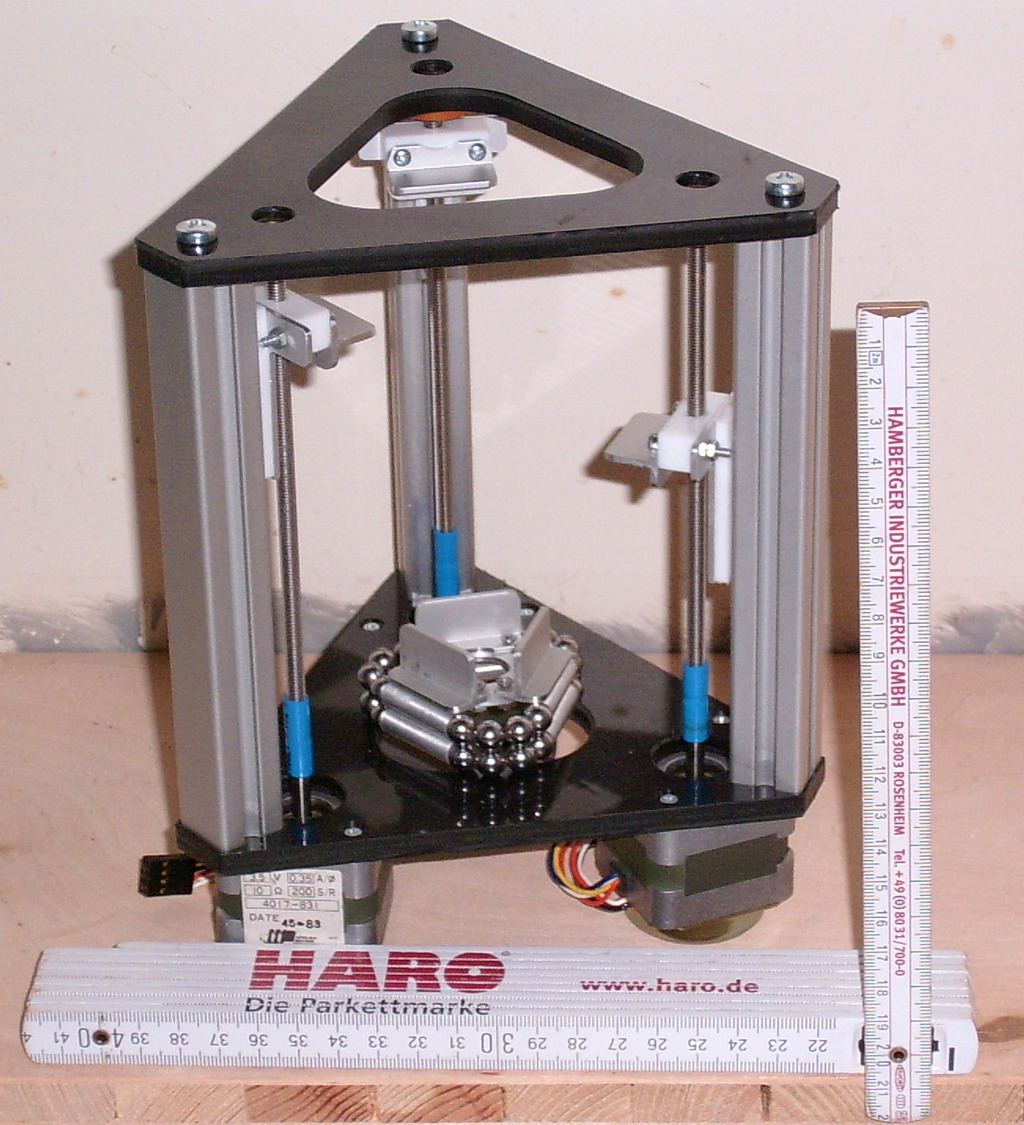
... here is an image of my vertically aligned Tripod-repstrap-demonstrator - i only have to mill the fittings for the ball-magnets, so next week the mechanic is ready, and i can search my driver-boards ...
The height is 21 cm, footprint nearly 17x17cm and the working area is a cylinder of 6cm diameter and nearly 8 cm height with an estimated accuracy of 10 microns or better (not in every zone the same accuracy because of the angular positioning).
With longer linear drives the working area is scaled up appropriate - maybe i'll receive 3 motorized linear stages from ISEL with 85cm height and 55cm travel, then the size would be 60x60x85 cm with a working area of nearly 45x45 cm and 40 height ...
Viktor
|
Re: Parallel-kinematics versus string-pod November 09, 2007 02:40PM |
Admin Registered: 17 years ago Posts: 1,487 |
|
Re: Parallel-kinematics versus string-pod November 09, 2007 04:55PM |
Admin Registered: 16 years ago Posts: 13,884 |
|
Re: Parallel-kinematics versus string-pod November 16, 2007 10:29AM |
Registered: 16 years ago Posts: 25 |
Viktor:
I am a computer scientist grown up in the era of 8bit microprocessors. Writing a program that takes (x, y, z) and gives string moves is easy. Building a machine is kinda tricky... Conclusion: I like your idea very much!
Actually, I also thought about using tapes for z-control. This would handle only one degree of freedom. But the direction of the tape would not change.
Image 'Seil-Tripod1.JPG' shows that the carrying wires of your your string-pod run over rolls. Moving up or down the extruder would change the amount of wire running over the roll which would make exact computation of movement a bit more challenging.
Actually, I expect that even horizontal moves would give changes in wire length since the wire would slide over the roll / axis. Your photo of your prototype is a bit too coarse to recognize en detail how it works.
Anyway, I will think about it over the weekend. Also have a nice one!
Howie
--
Airspace V - international hangar flying!
[www.airspace-v.com] for tools and toys
|
Re: Parallel-kinematics versus string-pod November 16, 2007 03:17PM |
Admin Registered: 16 years ago Posts: 13,884 |
Hi Howie,
... for more details of the parallel-axis tripod and a video, where i manually play the kinematics, you can go to the actual builders blog: [builders.reprap.org]
For another stringy mechanic you can look on the drawings in my third post here: [forums.reprap.org]
Viktor
... for more details of the parallel-axis tripod and a video, where i manually play the kinematics, you can go to the actual builders blog: [builders.reprap.org]
For another stringy mechanic you can look on the drawings in my third post here: [forums.reprap.org]
Viktor
|
Re: Parallel-kinematics versus string-pod November 19, 2007 03:08AM |
Registered: 16 years ago Posts: 25 |
Ummm... sorry, Viktor! I missed that you changed the string (or rod) arrangement from vertical to horizontal. Thought about it over the weekend. This is an ingeniouw approach! My plan to build such a device is getting much clearer now. Seems that I will buy some Meccano parts to build a prototype...
Howie
--
Airspace V - international hangar flying!
[www.airspace-v.com] for tools and toys
Howie
--
Airspace V - international hangar flying!
[www.airspace-v.com] for tools and toys
|
Re: Parallel-kinematics versus string-pod November 19, 2007 05:44AM |
Admin Registered: 16 years ago Posts: 13,884 |
Hi Howie,
... not to mismatch, the 'Seil-Tripod' was only a sketch to demonstrate wire-feeding mechanics, my actual Tipod is built with threaded rods, not with wire-feeding and the images from the other wire-driven system are from an old laserplotter, i built some years ago.
Tell me, which concept is your target basis, then i can send you probably some more infos ...
Viktor
|
Anonymous User
Re: Parallel-kinematics versus string-pod December 03, 2007 10:57PM |
Hello Viktor Dirks:
I would like build your tripod. I took a look at a string tripod by Alex Joni
[wiki.linuxcnc.org]
Are you going to make your software available to run the tripod.
I am working on a big cartesian machine at the moment it's going to take me
Some time and money. I would like to build a small tripod in the interim.
Best regards,
Andrew
Edited 2 time(s). Last edit at 12/03/2007 11:01PM by andrew777.
|
Re: Parallel-kinematics versus string-pod December 04, 2007 01:43AM |
Admin Registered: 16 years ago Posts: 13,884 |
Hi Andrew,
... i'll send you the software, when it's functional (can take a while). When you need the formulas for XY-output in the plane, then i'll think it over, should be no problem, it's much simpler then my multi-angle-mechanic ...
In the meantime you can try with emc/emc2 - here you can drive tripods too.
The string-tripod is a very simple and easy to setup system, so you can play with every driver-motor-combination without real costs
Many years ago i tried with a 'joy-string', where you have two identical wire-tripod-setups one over the other with some space between (~50x50x50cm or so), so you can fix a stick between the two wire-tripods.
With a more complex controlling software it was driven as hexapod or when applying encoders instead of the motors, then you have a 6-dimensional 'Joystick' (from this comes the 'joy-string'), where you can measure the position and angular orientation of the stick in the complete area between the encoder-planes.
Please send me a message, so i havent't to dig through the posts to contact you in future ...
Viktor
|
Re: Parallel-kinematics versus string-pod December 04, 2007 03:10AM |
Admin Registered: 16 years ago Posts: 13,884 |
Hi Andrew,
... here a first shot ...
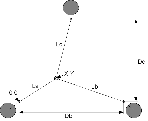
With your setup and the measuring-convention from the image below i have this conversion for every X,Y-tupel:
La = SQRT(X^2+Y^2)
Lb = SQRT((Db-X)^2+y^2)
Lc = SQRT((Db/2-X)^2+(Dc-Y)^2)
So when you start in the middle, then you have to move through converting the relative X,Y-displacement in La,Lb,Lc-displacement (look for right +/- moving) for shortening and elongating the wires synchrone ...
Viktor
... here a first shot ...
With your setup and the measuring-convention from the image below i have this conversion for every X,Y-tupel:
La = SQRT(X^2+Y^2)
Lb = SQRT((Db-X)^2+y^2)
Lc = SQRT((Db/2-X)^2+(Dc-Y)^2)
So when you start in the middle, then you have to move through converting the relative X,Y-displacement in La,Lb,Lc-displacement (look for right +/- moving) for shortening and elongating the wires synchrone ...
Viktor
|
Re: Parallel-kinematics versus string-pod December 04, 2007 02:51PM |
Admin Registered: 16 years ago Posts: 13,884 |
... by the way - by rethinking the wire-systems i realized, that this could be an extreme cheap'n'easy repstrap-basis ...
With some ball-gliders, magnets and a steel-plate (or a MDF-plate with an atached iron-sheet) above the wire-plane i can apply a toolhead, which is fixed through the magnets upside-down at the plate, glides freely around with the ball-gliders and is positioned by the wire-tripod.
With good magnets it's no problem to hold some kilograms upside-down, so the toolhead, the extruder/syringe and the support should be manageable ...
With a second wire-setup there could be a hoovering plate under the construction, which could be elevated in Z up and down, to complete the 3-dimensional repstrap.
Imagine a wire-tripod-repstrap fixed under the ceiling, which lowers the bottom-plate with the fabbing-process, so the ready parts comes down automatically and in idle-mode the aparatus is 'vanished' to a thin plate under the ceiling - maybe with some keen paintings on the bottom
I estimate an extreme low count of mechanical parts and assembly-working:
- 4 driving motors: 3 for the wire-tripod, 1 for the elevator
- some meters of thin steel-wire
- basis-plate with iron-sheet (for the magnetic fixing)
- bottom-/elevator-plate
- 3 ball-rollers
- 3 strong NdFeB-magnets
- upside-down-tool-head with extruder and feeding
- rolls for wire-feeding
- some scrap for assembly ...
The electronic is the same (with 4 motors) and the software has an additive converter from X,Y- to {La,Lb,Lc},Z-paths, as mentioned in the post above ...
Viktor
Edited 1 time(s). Last edit at 12/04/2007 02:56PM by Viktor Dirks.
|
Anonymous User
Re: Parallel-kinematics versus string-pod December 04, 2007 03:47PM |
Re: Parallel-kinematics versus string-pod
Posted by: Viktor Dirks (IP Logged) (RepRap Guru)
Date: December 04, 2007 09:10PM
Hi Andrew,
... here a first shot ...
With your setup and the measuring-convention from the image below i have this conversion for every X,Y-tupel:
La = SQRT(X^2+Y^2)
Lb = SQRT((Db-X)^2+y^2)
Lc = SQRT((Db/2-X)^2+(Dc-Y)^2)
So when you start in the middle, then you have to move through converting the relative X,Y-displacement in La,Lb,Lc-displacement (look for right +/- moving) for shortening and elongating the wires synchrone ...
Viktor
Dear Viktor:
Thank you for your rapid response. I know how to control a string tripod by reading an article by Graham Stabler.
I want to build a string tripod and a parallel kinematic tripod. Two small demonstrators. Attached is the article by
Graham Stabler if you haven't seen it already. This is quoted from a e-mailI received from Graham Stabler:
"So you will have three variable length cords going to a single point.
Using the same notation as the pdf and putting the third motor at X3
Y3 then the equation is simply:
r = sqrt((Y3 - Y) + (X - X3))
Draw it out and it should make sense.
> The next project would be 3-D.
> Wouldn't a 3-D tripod use (mathematically speaking) three spheres
> intersecting at 120 degrees, we then can use spherical coordinates
to determine the radiuii of the spheres for the end lengths of the
> cables.
You don't need to use sherical co-ordinates just pythagorus again but
this time in 3D
R = sqrt(x^2 + y^2 + z^2) the rest is just as in my pdf more or less,
I'll leave it as an exercise for you or I will do it for you but only
when you get the 2D version working
This should explain why the 3D pythagorus works:
[www.education.vic.gov.au]
x^2+c^2 = d^2
but
a^2 + b^2 = x^2
so
a^2+b^2+c^2 = d^2
and hence
d = sqrt(a^2+b^2+c^2) (but use a=x, b=y, c=z)
Graham"
Thanks,
Andrew
|
Re: Parallel-kinematics versus string-pod December 04, 2007 04:32PM |
Admin Registered: 16 years ago Posts: 13,884 |
Hi Andrew,
... thanks for the file - the two-wire-spraybot is a good idea too
Actually i'm 'breeding' a bit on my parallel-tripod ( [builders.reprap.org] - see "Assembling the Tripod..." ) --- i didn't want to reconfigure the ISEL-controller as i need it for the CNC-repstarp (but i shortly got a second interface-card, so i can play and mess around with it)
Now i try to reactivate my 12 years old microstep-drivers, so with some more time i'll start with 'oldstyle parallel-port-driving' or reprogramming a 80C51-mikrocontroller as serial interface --- then i can drive any motor-setup, i want ...
If you are interested in the parallel-kinematic tripod with the magnetsphere-hinges, then i can give you all the infos you want (sketches, dimensions, vendors).
For the stringy-tripods i have only concepts and sketches, no real assemblies.
Say what's your limits (time, parts and/or money), then we can select the easiest way to a kinematic system ...
Viktor
Sorry, only registered users may post in this forum.