Easy to build linear stages
Posted by VDX
|
Easy to build linear stages October 19, 2007 02:15PM |
Admin Registered: 16 years ago Posts: 13,886 |
Hi all,
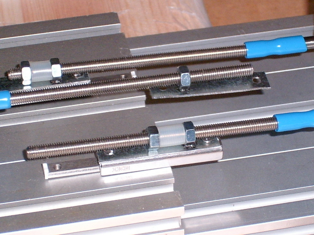
... i tried an idea for simply assemble of small motorized linear stages for a noncartesic micro-reprap and found a good intro - this should be working with bigger and longer linear drives too.
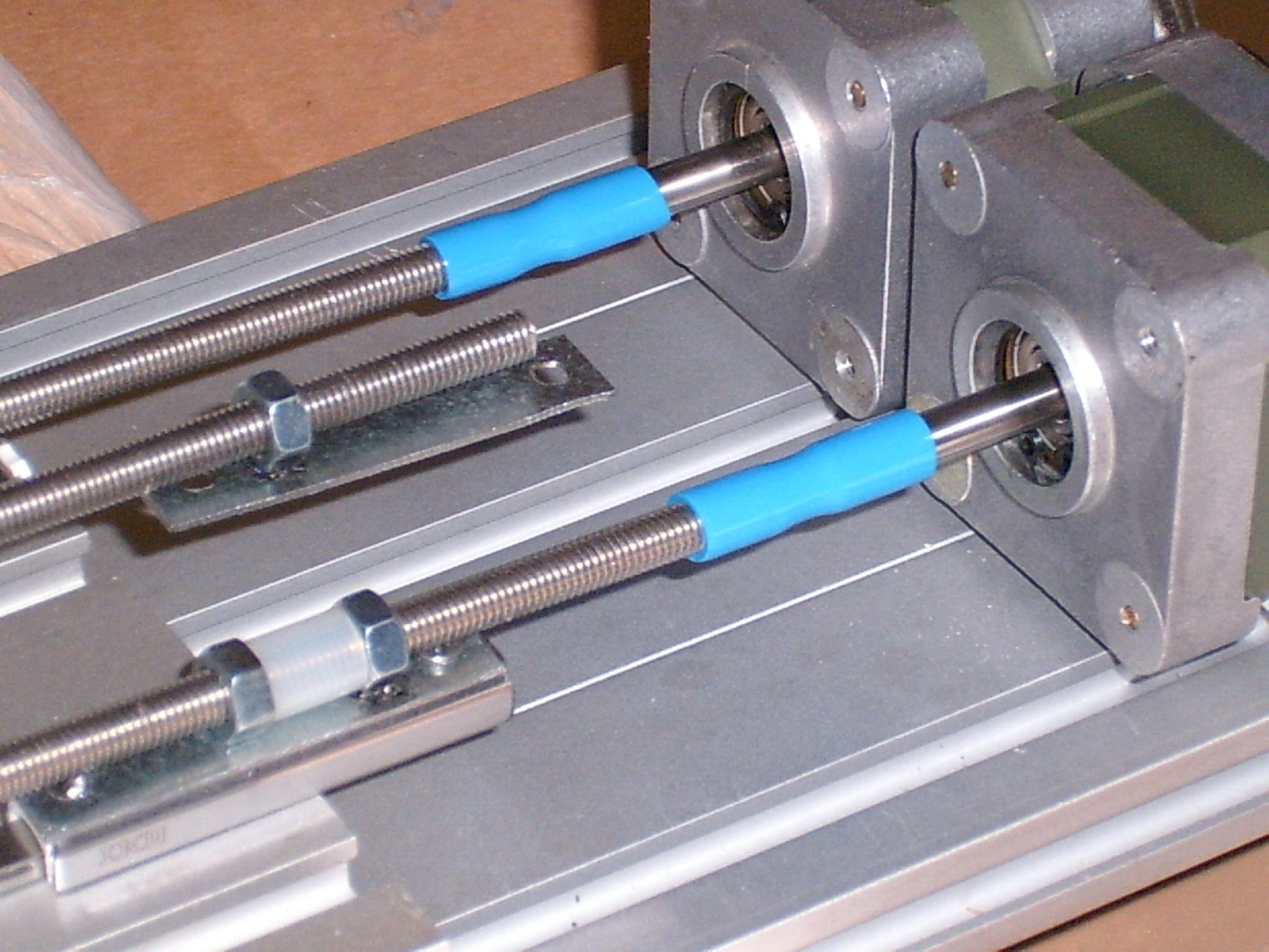
As the threaded rod has the same diameter, as the motor-shaft, i could use short pieces of pneumatic tubes (elastic and stiff in the same time) as couplings.
The rods i found in our 'Bauhaus'-toolstore, they are from rustfree steel, 5mm in diameter and much smoother in the surace, then the 'normal' threaded rods from brass or iron.
I laserwelded the nuts on small metal sheets and screwed the sheets on the linear stages (the plate for fixing the spherical magnets for my magnetic joints should be between them later).
For reducing the slack, i compressed a short elastic silicone-tube between the fixed and a free nut -- in the tube could be lubricating wax too ...
Viktor
... i tried an idea for simply assemble of small motorized linear stages for a noncartesic micro-reprap and found a good intro - this should be working with bigger and longer linear drives too.
As the threaded rod has the same diameter, as the motor-shaft, i could use short pieces of pneumatic tubes (elastic and stiff in the same time) as couplings.
The rods i found in our 'Bauhaus'-toolstore, they are from rustfree steel, 5mm in diameter and much smoother in the surace, then the 'normal' threaded rods from brass or iron.
I laserwelded the nuts on small metal sheets and screwed the sheets on the linear stages (the plate for fixing the spherical magnets for my magnetic joints should be between them later).
For reducing the slack, i compressed a short elastic silicone-tube between the fixed and a free nut -- in the tube could be lubricating wax too ...
Viktor
|
Re: Easy to build linear stages October 21, 2007 01:49PM |
Admin Registered: 16 years ago Posts: 13,886 |
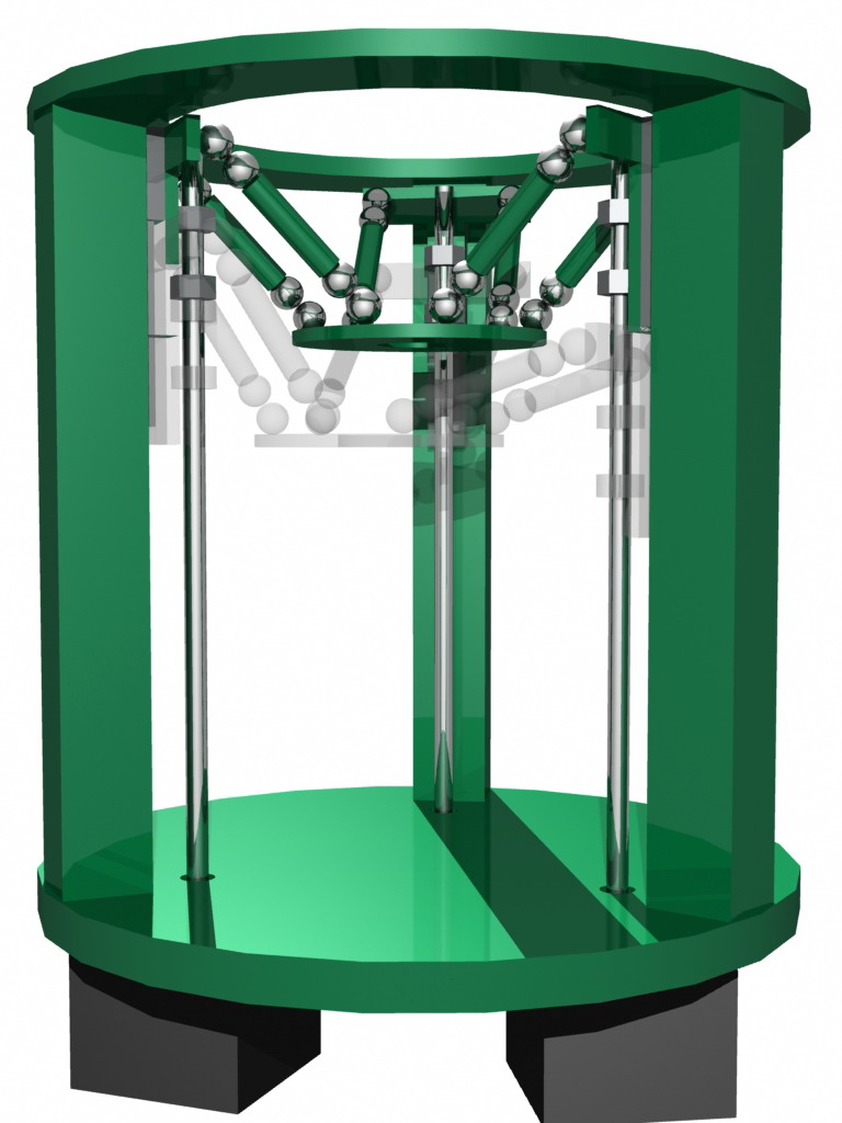
... here is my idea for a tripod-setup with the 'Easy to build linear stages' and the self-assembling magnetic joints from [forums.reprap.org] .
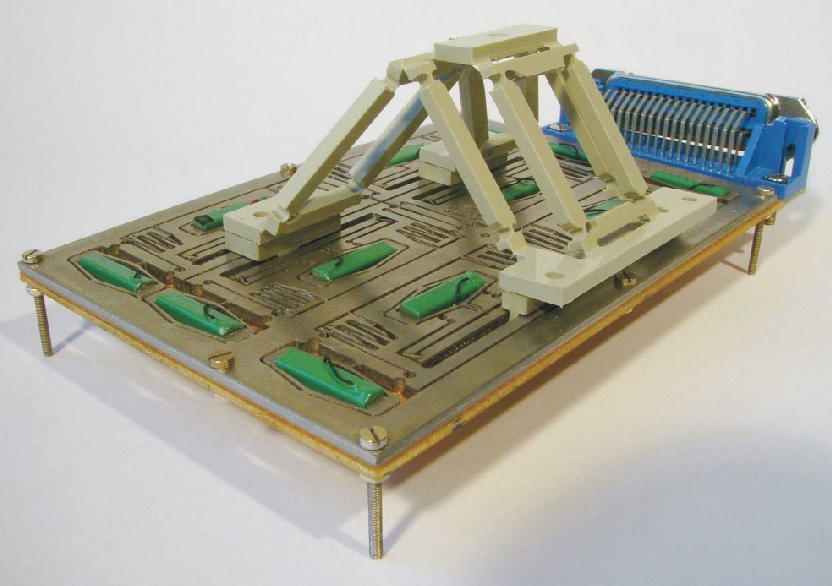
The green parts could be entirely made from plastics (reprapped, molded or milled) or from aluminium, the spheres are my joint-magnets and the linear stages from the previous post ...
The transparent insert is a displacement-sample of the toolhead, to demonstarte the planarity of the tool-platform (works in the real buildup-sample very good).
In this setup i have only linear stages with 40mm way, so my working area is a cylinder-/ovoid-space with maximal 30mm diameter and maybe 20mm height (but with submicron accuracy!) - with longer linear bearings then i would have a bigger setup and also a bigger working area ...
As you can see, the basic-system has a very simple structure with only 12 fabbed parts.
The assembly is very easy -- fix the plates on the quad-sticks, apply the linear stages and then combine the magnets with the right poles, so the toolhead would 'snap on self' ...
I have to apply three home-/end-switches and insert the tools - in my case it's a syringe filled with glass-paste and the output-fibre of a diode-laser for sintering the paste 'on the fly'.
The electronics is the same as in the reprap or a 4-axis-cnc-mill, but the software must handle the conversion from STL to planar moving of the tool-head.
I aready solved the algorhythms for a 2-axis-kinematic with a separate elevated Z-axis and i'm now on the 3-axis-conversion for fabbing on a fixed surface ...
Viktor
Edited 1 time(s). Last edit at 10/21/2007 02:08PM by Viktor Dirks.
|
Re: Easy to build linear stages October 21, 2007 03:11PM |
Registered: 16 years ago Posts: 622 |
Viktor,
I'm not understanding how the tool head platform is moving. You said that the green objects were fabbed. Wouldn't the green cylinders between your magnetic joints have to be linear actuators in order to move the platform around?
Also, how many degrees of freedom does this think have? Does the tool head platform always stay level or does it tilt?
Demented Chihuahua
|
Re: Easy to build linear stages October 21, 2007 04:40PM |
Admin Registered: 16 years ago Posts: 13,886 |
Hi Demented,
look on the linked images and files in [forums.reprap.org] - here i described the tripod-system and linked some infos in my answer to Zach, where you have some background ...
In my concept the three linear stages aren't in a plane as usual, but parallel, so i have a more cylindrical defined working area - here i can perform a straight Z-movement with moving all three axis synchrone.
The thin rods beside the quad sticks should be threaded for better visualisation, but i didn't found a thread-construction plugin or script, so i used smooth cylinders instead - but you can look on the images in the first post, to see the real-life setup ...
If one axe moves up or down, then the spheric magnets and the 'green zylinders' act as passive joints and push or pull the platform against the other non-moving stages, so the platform moves in radial curves.
Through the double-joints per stage the platform ist strictly defined to a horizontal position, so it moves freely around, but stays plane and didn't rotate or tilt.
With calculated moving of all three axes i can perform every path, curved or linear - i have to transform every moving in single steps, which combines the angular disposition of the three stages to perform a smooth linear path ...
For a 2-dimensional kinematic i got it, it was not so complicated with the trigonometrics ...
For the synchronous 3-dimensional moving i have to expand the kinematics from 2- to 3-fold angular calculations, but i'm on the way
Viktor
|
Re: Easy to build linear stages October 21, 2007 06:02PM |
Registered: 16 years ago Posts: 246 |
I remember reading, it might have been here, that using elastic tube to connect the motor to the drive rod produces somewhat problematic results. Something about the motor leading the shaft a bit, and the shaft catching up a bit. This is in the same vein as why I was told gears aren't used very much, it introduces slop.
A clever bit of work, anyway.
I didn't find the reference to the slop being a problem, but I did find where I'd seen that type of connector before.
[www.engadget.com]
Good luck, and good work.
A clever bit of work, anyway.
I didn't find the reference to the slop being a problem, but I did find where I'd seen that type of connector before.
[www.engadget.com]
Good luck, and good work.
|
Re: Easy to build linear stages October 21, 2007 06:40PM |
Admin Registered: 17 years ago Posts: 7,879 |
A slightly elastic coupling can be beneficial when coupling high inertia loads to a stepper motor stepping slowly. As well as sorting out shaft misalignment it reduces vibration. Sure it lets the motor lead the shaft but with a direct connection and a significant mass the motor would be forced to lag its phase pattern anyway.
When extruding a straight line you don't really want a stepped response, and it is impossible to achieve anyway with a non zero mass. You actually want constant velocity from the stepper motor. To do that you need to feed it with sine and cosine waveforms, which is what micro stepping approximates to. If you listen to any of the videos of my machine you will notice how noisy the z axis is compared to X and Y. It is half stepped whereas X and Y are micro stepped. I am planning to replace the metal shaft coupler with a rubber one to reduce the noise. I don't think it will affect accuracy much because the load on my z-axis is constant.
It also affects the stop response. The load wobbles about the stop position with a damped sine wave response. The frequency is determined by the inertial mass. By separating the load mass from the motor mass you can get a much faster oscillation which dies away more quickly.
[www.hydraraptor.blogspot.com]
|
Re: Easy to build linear stages October 22, 2007 01:18AM |
Admin Registered: 16 years ago Posts: 13,886 |
Hi Sean and nophead,
... i knew, that elastic tubes will shorten a bit, when twisted.
For this reason i searched a bit, until i found the perfect material:
It's a merely stiff pneumatic tube - you can have them in different shore-values, my type is so stiff, that i can't sense any distortion, when twisting the rod against the motor-shaft (i had to apply a lot of force to screw the rod into the tube!)
But it's elastic enough, to let the rod and the shaft go into.
With heating a bit you can make it more elastic for easier assembling, after cooling down it's a very durable connection ...
Viktor
|
Re: Easy to build linear stages October 22, 2007 09:11PM |
Registered: 16 years ago Posts: 82 |
Cool idea. It looks pretty scalable, at least in the Z direction. The only issue is that you don't get much horizontal motion. It probably has nearly enough range to make it's own structural beams though, and that's better than the Darwin in that regard. It's also nice because all of the axes are in the same direction, simple, and redundant parts-wise. Easier to reprap that way, I think.
Isn't it true that it would be hard to get the platform to move much in the x and y direction without losing a lot of height? Especially if you scaled the diameter up, so you would have more range, every bit of movement sideways loses height. I guess you'd have to have your computer compensate on the other two actuators.
Random side note: it is interesting that most of the useful positioning systems in 3 dimensions all have at least 3 axes of motion. Even if they are oriented in weird ways, such as this one, or spherical coordinates, etc. I wonder what other configurations we could come up with? Or maybe just Viktor. He seems to have the most experience with exotic fabricating robots.
|
Re: Easy to build linear stages October 23, 2007 02:25AM |
Admin Registered: 16 years ago Posts: 13,886 |
Hi Samuel,
... in this sample-setup i have only linear bearings with 40mm free run, so the maximal displacement in XY would be at 30 millimeters with a 'safe' heighth-zone of 10 millimeters over the whole working area (in the centre then more, so at 30 millimetres too).
I designed this 'micro-fabber' for a special problem, where we have to fab mikrosensors from a ceramic-paste with gold-inlays in an overall size of 10x10 millimeters and a height of 5 millimetres, but with an targeted acuracy of 0,5 microns!
I'm actually arguing with ISEL to get three 85 centimetres long motorized linear stages with then more than 50 centimetres free way for my experiments (see here: [www.iselautomation.de]〈=en&oldlang=de - maybe for free!), then i can build a 90 centimetres high system with a working-area of maybe 45x45 centimetres, 20 centimetres 'safe' height and an accuracy of approximated 25 microns ...
For the 'Three-axes-setup': - you need at least three axes to perform a 3-dimensional path, sometimes, as with hexapods (stewart-platforms) there will be used even 6 axes for 6 degrees of freedom (XYZ, rotate, tilt and nip) ...
So in practical you need an axis for every degree of freedom, you want.
If you use more, you overdefine your setup, but you can rise power, accuracy, stiffness or some other tricky values too, so it's sometimes worth the price
Viktor
Edited 1 time(s). Last edit at 10/23/2007 02:36AM by Viktor Dirks.
|
Re: Easy to build linear stages October 23, 2007 10:59PM |
Registered: 16 years ago Posts: 82 |
Thanks for the information on the scale of your machine. It always amazes me how small your devices are. Whom do you work for again? Sounds like a neat place, from what you've been able to design there. 
I've known for a long time that it takes as many axis as you want degrees of freedom, having experimented with various coordinate systems in a 3d game I've been working on. But it continues to amaze me how you can combine them in different ways, and still get the same degree of freedom.
What do you think of the idea of using pneumatic/hydraulic "muscles" instead of linear actuators? In theory it would make it more "reprapable," no? You'd need plenty of feed back, of course, but if you go slowly enough, you could get the necessary precision, for a regular reprap anyway.
-Samuel
|
Re: Easy to build linear stages October 24, 2007 01:37AM |
Admin Registered: 16 years ago Posts: 13,886 |
Hi Samuel,
... i'm working now at [www.arteos.com] - a small company with 4 employees, where i have to develop and realize all kinds of micro-stuff (sometimes nano- too) ...
From 2000 to 2006 i made the same thing for GERWAH - here i invented and built some micropositioning systems ( [www.gerwahmikro.com] ), microgrippres and special video-microscopes (with the tenfold field-of-view then normal), to realize stereo-vision in the micron-area ...
But most of my 'development' i made at home - sometimes just for fun, but eventually for going a step further in my preferred direction -- in near future i hope to build every needed type of sophisticated hardware (or electronics too) in my basement ...
For pneumatic/hydraulic muscles - they shouldn't be slow, to achieve high accuracy.
Some years ago FESTO ( [www.festo.com] ) build a pneumatic cartesian pick'n-place-roboter with pairwise counteracting pistons with a working area of some 40x30x20 centimetres and an accuracy of 100 microns or so - the positioning speed was in the range of metres per second!
And if you imagine the fast and precise moving of calmaries and octopusses (?), then you can imagine, what an highly evolved hydraulic structure can perform ...
Viktor
|
Re: Easy to build linear stages October 24, 2007 02:26AM |
Registered: 16 years ago Posts: 34 |
Regarding degrees of freedom - if your print head is following a fractal, area filling guidance rail laid out in two dimensions, you'd only need two axis of freedom for 3D positioning. Or if it followed a space filling guidance rail it'd only need one axis of freedom for 3D positioning. This is just theoretical though, apart from the complexity of such a guidance rail, the time to position a head to a specific point would be prohibitely high as the accuracy of the rail was increased.
[en.wikipedia.org]
Sorry for diverging from practical solutions into fancy theoretical models.
[en.wikipedia.org]
Sorry for diverging from practical solutions into fancy theoretical models
.
|
Re: Easy to build linear stages October 24, 2007 02:57AM |
Admin Registered: 16 years ago Posts: 13,886 |
Hi zzorn,
... you're right, but this would extend the building time per slice (in a 2D-Peano-curve with rounded edges) from minutes to days or weeks, if you want an usable accuracy
I had some ideas for reducing the amount of motors too - if i use two rotating axes, where an arm moves horizontally (like the arm of a phono) and the other turns a threaded rod, where i can change with clamps the modus between going up and down (wiht the thread) or rotate only (thread in free-run).
But then i have three 'axes' too - two angular for moving and a binary (clamps on/off) for changing between Z-movement or rotation in a plane ...
Viktor
|
Re: Easy to build linear stages October 24, 2007 01:29PM |
Registered: 16 years ago Posts: 82 |
So how would you implement that fractal following head in mechanics? I understand how to do it with a mathematical function (sort of) but that is just a compression method, i.e. one number as input becomes 3 numbers (cartesian coordinates) as output. Is the goal to reduce the number of motors? (inputs) If so, it sort of makes sense, but it's very complicated, and there are other was doing that.
I can imagine one motor controlling three dimensions, i.e. rotate counterclockwise, and the carriage goes sideways, rotate clockwise, and the carriage goes up. When it hits the end of either range, the carriage goes the other way, using something like a doubly threaded rod, or riding down the other side of a chain over a pulley. It would probably come back bit to the side when it hits the end horizontally, to allow the third dimension.
Or, you could use the one motor to power a pump to use those elastic muscles, and just switches to control in which direction the carriage moves.
In all of these systems though, you still have to have the moving parts for three dimensions. So it would only help for reducing motors, right?
Please correct me if I'm wrong. I hate being wrong.
-Samuel
|
Re: Easy to build linear stages October 24, 2007 01:56PM |
Admin Registered: 16 years ago Posts: 13,886 |
Hi Samuel,
... it's only theoretical
In practical issues the one-motor-per-axis-approach ist the best start.
It's not so essential, if the setup is cartesic, polar, polypod or other - in the cartesic systems is the software easier to create, some others (like my tripods) are very easy to assemble, but the controling is a mess ...
When i'll have a fabber capable of making elastic resins, then i'll try some concepts of 'tentacle-monsters' for microassembly
Imagine some 3-fingered polyps ( as in this thread [forums.reprap.org] ), sitting around a fabbing-zone with supporting systems and magazines around, making simple electronics and complex hardware - and the complete fabber is not much bigger, then a laser-printer ...
Viktor
|
Re: Easy to build linear stages October 24, 2007 02:17PM |
Registered: 16 years ago Posts: 622 |
Hi all,
I'm really fascinated by this pneumatic muscle RepRap idea. The very concept of being able to get rid of the motors from the RepRap--which have a tenancy of being un-fabable--is good. Would you still need to buy a pump to run the pneumatics? Could some sort of piston pump be realized?
How about a fluid that reacts volume-wise to the application of electricity. Fill a sealed cylinder with this stuff and run a current through it at different voltages and you would have variable pressure differentials to do work with. I'm sure this has been done before. That way you would have even fewer moving parts and thus less down time through breakage.
Demented
|
Re: Easy to build linear stages October 24, 2007 02:29PM |
Registered: 16 years ago Posts: 622 |
Hi again,
Yep, I was right this sort of thing is being looked into but not at the level I had imagined.
[www.rsc.org]
There must be other materials out there that do this same thing but I have to have more time to do the research to get to them. Don't have time in between classes right now.
Cheers!
Yep, I was right this sort of thing is being looked into but not at the level I had imagined.
[www.rsc.org]
There must be other materials out there that do this same thing but I have to have more time to do the research to get to them. Don't have time in between classes right now.
Cheers!
|
Re: Easy to build linear stages October 24, 2007 04:34PM |
Admin Registered: 16 years ago Posts: 13,886 |
Hi Demented,
... very interesting!
The 90% volume-change in 50 seconds isn't so clear for me - 90% change would be exorbitant, but the reacting time is a bit longlasting ...
Another interesting concept: - i experimented sometimes with ferrofluids and magnetorheological fluids (in special: carbonyl-iron-microspheres in different solvents) and found some methods for pumping volumes and apply pressure ...
Imagine an elastic tube with two solenoids around - when i fill the tube with magnetorheologic fluid and apply a magnetic field through the tube, the fluid stiffen very fast and block the tube (=magnetic valve!)
With a similar setup but another solenoid-setup i can make a peristaltic pump, which can pump and move extreme small volumes per second, but with high pressures possible - and it's only some millimetres in overall size!
The biggest and complexiest parts are the solenoids, which can be manually manufactured through winding wires on iron-sticks, so you need only some tubes, thin isolated wire, iron-rods and the electronics, to build pumps and switching valves for a hydraulic system, which transports the magnetorheological fluid through tubes and capilaries ...
Viktor
|
Re: Easy to build linear stages October 24, 2007 04:53PM |
Registered: 16 years ago Posts: 82 |
How hard do you think it would be to get a reprap to make good, air or water tight tubes? If it could do that, I could easily see a reprap that is structurally based on jointed plastic tubes and hydraulic or pneumatic muscles. All you'd have to do is design a reprap that is structurally based on tubes that could all fit inside its working area. Actually, using tubes sounds like a generally good idea, because then you could have more standardized pieces, less metal bolts and rods, and can make a lot more interesting designs, such as Viktor's above. There are a lot of interesting properties of hinged triangles that could be taken advantage of that way.
Also, it seems that tubes are probably and integral part of making some kind of pump for the hydraulics. It would be easier to make an electromagnetic pump than it would a nice, precise, stepper motor. All it would be required to do is have a consistent psi output, and that can probably be done with simply wound electromagnets. In that case, I think we're nearing the lower bound of what the reprap needs to do itself. Obviously, since the reprap needs a computer to control it, you have electricity. Carrying on beyond that level of self-sufficiency leads to madness and insanity. And human powered hand-held clay extruders.
-Samuel
|
Re: Easy to build linear stages October 24, 2007 08:39PM |
Registered: 16 years ago Posts: 622 |
Samuel,
And why not Human Powered Hand-Held Clay Extruders? These HPHHCEs seem to be the perfect solution to agrarian societies around the world (always assuming agrarian societies need a solution!) without resorting to ecologically costly machinery.
I'm not necessarily advocating anything so primitive--I think we can do better than that as a first go--and low level. Those people--in software, at least--end up writing their own compilers in Assembly. Crazy people. :-)
Simplicity is, however, truly beautiful. Reducing RepRap to its most simple and basic starting point just seems appropriate, as I'm sure you would agree.
Demented
|
Re: Easy to build linear stages October 25, 2007 01:37AM |
Admin Registered: 16 years ago Posts: 13,886 |
... it seems, we've lost the connection to the basic reprap a bit
It's obvious, that simplifying the reprap-setup would be good for spreading the ideas and fabbing possibilities for selfmade home-manufacturing worldwide - and here is my aim, to initiate faster progress ...
It's obvious too, that noncartesic systems need a more sophisticated software, to control them, but if the controls are programmed once, the software can be copied for free, so this isn't the point.
I'm playing around with this kind of ideas since 1985 or so, as i first read a scientific article about 'molecular gears', as mentioned in Eric Drexlers papers.
In the last years i found much more interesting stuff, so my hope was to achieve micro-fabbing-capabilities in some years, to perform nanotech-manufacturing at home in some decades - but the progress was much slower, then i calculated, because of the huge amount of money, needed for high-precise apparates and processes ...
Actually the way to micro-fabbing is easier, then twenty years ago, and there evolved some interesting ideas and alternative methods, so i'll start a new run
Viktor
|
Re: Easy to build linear stages October 25, 2007 04:54PM |
Admin Registered: 16 years ago Posts: 13,886 |
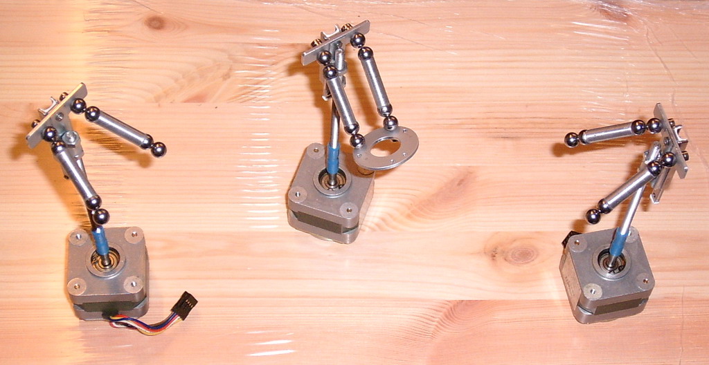
... 'back to the roots' and to real life
Here i assembled the linear axes and temporarily atached the magnetic joints and rods - i have to mill the 45
Edited 2 time(s). Last edit at 11/03/2007 01:44PM by Viktor Dirks.
Here i assembled the linear axes and temporarily atached the magnetic joints and rods - i have to mill the 45
Edited 2 time(s). Last edit at 11/03/2007 01:44PM by Viktor Dirks.
|
Re: Easy to build linear stages October 26, 2007 06:22AM |
Agreed about software controller for a tripod not beeing a big problem - after all, software can already be easily be copied once written (in this case it sounds like a bit of trigonometry should solve it), we just need to come up with an easy to copy 3d printer.
I have set up a simple air muscle, and am experimenting with handmade solenoid valves at the moment. I'll post some pictures in a bit.
-zzorn
I have set up a simple air muscle, and am experimenting with handmade solenoid valves at the moment. I'll post some pictures in a bit.
-zzorn
|
Re: Easy to build linear stages October 26, 2007 03:09PM |
Admin Registered: 16 years ago Posts: 13,886 |
... i've found some stuff from my experiments with ferrofluids some years ago ...
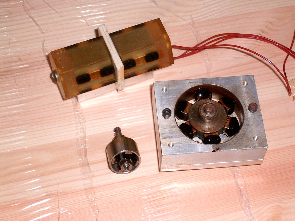
In the first image you can see an (UV-epoxy-fabbed) electro-magnetic nanopositioner with ferrofluidic-bearings and two prototypes of peristaltic pumps (without the normally inserted soft air-feeding tubes) - you can see the ferrofluid inside the nanopositioner or on the teeth of the pump-magnet-gears.
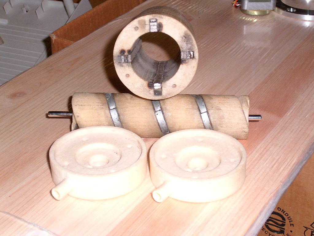
The second image shows a big setup for a rotating 'archimedic' pump, which when filled with ferrofluid (which forms fluid wall-structures) can transport gases or waterbased (oleophobe) fluids with a very high accuracy - this was made from stark on a powder/inkjet-3D-printer.
With iron-dust-based magnetorheological fluids i built some other types of pumps, valves and damping-systems, so there is a wide area of applications with fabbed hydraulic or pneumatic structures ...
Viktor
In the first image you can see an (UV-epoxy-fabbed) electro-magnetic nanopositioner with ferrofluidic-bearings and two prototypes of peristaltic pumps (without the normally inserted soft air-feeding tubes) - you can see the ferrofluid inside the nanopositioner or on the teeth of the pump-magnet-gears.
The second image shows a big setup for a rotating 'archimedic' pump, which when filled with ferrofluid (which forms fluid wall-structures) can transport gases or waterbased (oleophobe) fluids with a very high accuracy - this was made from stark on a powder/inkjet-3D-printer.
With iron-dust-based magnetorheological fluids i built some other types of pumps, valves and damping-systems, so there is a wide area of applications with fabbed hydraulic or pneumatic structures ...
Viktor
|
Re: Easy to build linear stages October 26, 2007 03:34PM |
Registered: 16 years ago Posts: 82 |
Viktor, what tools are necessary to make those micro-fabbers? Some of them seem pretty advanced. You said you were working for a small company. Is that where you do the design and construction of these micro-fabbers, or do you do that as a hobby?
Either way, they are very cool, and I wish I could make them myself. Unfortunately, I'm almost too cheap for reprap, hence my desire for muscles instead of motors, etc.
zzorn, sounds interesting. What are you using for your muscle and solenoids? I can't wait to learn how well they work.
I also agree that software is generally cheaper and easier than software. Sometimes more fun too, unless it happens to be programmed in Java. Not that I'd program in VB either. Sorry, I don't want to get sidetracked in language flame-war. Forget I mentioned it.
Edited 1 time(s). Last edit at 10/26/2007 04:06PM by Samuel.
Either way, they are very cool, and I wish I could make them myself. Unfortunately, I'm almost too cheap for reprap, hence my desire for muscles instead of motors, etc.
zzorn, sounds interesting. What are you using for your muscle and solenoids? I can't wait to learn how well they work.
I also agree that software is generally cheaper and easier than software. Sometimes more fun too, unless it happens to be programmed in Java.
Not that I'd program in VB either. Sorry, I don't want to get sidetracked in language flame-war. Forget I mentioned it.Edited 1 time(s). Last edit at 10/26/2007 04:06PM by Samuel.
|
Re: Easy to build linear stages October 26, 2007 04:14PM |
Admin Registered: 16 years ago Posts: 13,886 |
Hi Samuel,
... it's half-on-half - sometimes i'm employeed (as now) for starting a microtech-branch in a company, sometimes it runs at home ...
The parts i made on my own are mostly milled from aluminium or Delrin/POM on a ISEL-3D-mill.
The fabbed parts from UV-epoxy, inkjetted plaster or stark i've got from 3D-printing companies - sometimes in tech-cooperation for free, sometimes with custom developing in projects.
From 1986 until 1992 i had a 3D-mill at home, then i (unfortunately) sold it with a project of sign-making and engraving to a customer, so i had to pay for complex milling and sped down ...
From 2000 on i managed to install a small 3D-mill in every company, i was employeed, so there was some progress again
Actually i'm in a discussion with a company, which is replacing a bigger 3D-CNC-Dispenser-system, so it's possible, i'll get the old system for my repstrap - it's a complete ISEL-CNC-system, but with a Loctite-dispenser-head instead of a mill.
On the other side ISEL is willing to lend me some linear axes to develop a bigger tripod setup, if they could participate on my progress, so i'm a bit in a twister, which would be best ...
I hope seriously, that i could lay my hands on the old CNC-dispenser, then this would be a perfect repstrap
In the meantime i'm tingling around with smaller setups and testing diode-lasers as heat-curing- or cutting-heads for laminating plastic-sheets and 3D-paste-sintering ...
Viktor
|
Re: Easy to build linear stages October 26, 2007 04:16PM |
Registered: 16 years ago Posts: 82 |
Viktor,
I think I understand how the pump in the second image works, i.e. the ferro-fluid forms the screw for pushing your liquid. Does the ferro-fluid try and form-fit itself against the outer wall as it moves? Does it reduce friction?
About the first image though, I'm not exactly sure what I'm seeing. On the bottom and right it looks like you're using ferro-fluid to apply pressure to the hose that would normally be inside a peristaltic pump, but I'm not sure. Are there advantages to using ferro-fluid? i.e. lower friction etc.?
What about the device in the upper left? You said it was a nanopositioning device, but I can't figure out how it works exactly.
The devices are certainly cool, though, whether I can figure out how they work or not. How expensive is the ferro-fluid you're using? How useful do you think it would be for a reprap? And do you think we could make a reasonably capable ferro-fluid from oil and iron filings, or some other diy process?
Thanks,
-Samuel
I think I understand how the pump in the second image works, i.e. the ferro-fluid forms the screw for pushing your liquid. Does the ferro-fluid try and form-fit itself against the outer wall as it moves? Does it reduce friction?
About the first image though, I'm not exactly sure what I'm seeing. On the bottom and right it looks like you're using ferro-fluid to apply pressure to the hose that would normally be inside a peristaltic pump, but I'm not sure. Are there advantages to using ferro-fluid? i.e. lower friction etc.?
What about the device in the upper left? You said it was a nanopositioning device, but I can't figure out how it works exactly.
The devices are certainly cool, though, whether I can figure out how they work or not.
How expensive is the ferro-fluid you're using? How useful do you think it would be for a reprap? And do you think we could make a reasonably capable ferro-fluid from oil and iron filings, or some other diy process?Thanks,
-Samuel
|
Re: Easy to build linear stages October 26, 2007 04:40PM |
Registered: 16 years ago Posts: 82 |
Fascinating story. It seems that we're posting asynchronously. Let us know how it goes with trying to get those tools and pieces.
What do you think are the main advantages and disadvantages of a tripod system, compared to one of the standard cartesian systems? You seem to like them, and it sort of makes sense, but I'm not familiar with them enough to know exactly why.
Thanks,
-Samuel
What do you think are the main advantages and disadvantages of a tripod system, compared to one of the standard cartesian systems? You seem to like them, and it sort of makes sense, but I'm not familiar with them enough to know exactly why.
Thanks,
-Samuel
|
Re: Easy to build linear stages October 26, 2007 04:56PM |
Admin Registered: 16 years ago Posts: 13,886 |
Hi Samuel,
... the pump in the second image should be filled with ferrofluid, which forms fluid threads on the spiral-magnets and on the linear magnets inside the tube.
When i insert the spiral in the tube, both ff-thread-setups overcross and form cavities, which are surrounded by ferrofluid-walls.
When turning the spiral, the cavities moves in the corresponding direction (as in a archimedic-pump) and the trapped medium in the cavities (air or a fluid) will be transported from one end of the pump to the other ...
The peristaltic pumps in the first image works like normal blood-pumps (the ferrofluid can perform some pressure on a inserted tube), but this was a test for extremely soft tubes, because normal blood-pumps press the tubes so forcefull, that some blood-cells are smashed and coagulate and sometimes make thromboses.
With the 'soft-pressing' ferrofluid-teeth and a very thin-walled tube the pressing is so smooth, as if you grip and gently press the tube with your fingers, so the risk of mechanically induced thromboses is reduced ...
The nanopositioner was a early try of a dual-magnet/solenoid-positioner, where i trapped some permanentmagnets between (or here outside of) solenoids, so i can move the slider with current through the solenoids - for get 'nano-accuracy' i applied ferrofluid as stick-n-slip-free bearings between the solenoid-body and the epoxy-hull of the slider.
In later setups i trapped the moving magnets and the slider inside between two solenoids, so the ferrofluid was embedded inside too and the magnetic force could be shielded ...
Look here for the last setup and tech-specs of the ferrofluid-nanopositioner: [www.gerwahmikro.com]
The MP-1 is a 1-axis, MP-2 a 2- and MP-30 a 3-axis-positioner with a travelling range from 1 to 3 millimetres and an accuracy, which is dependant of the quality of your controller - the solenoids were driven between 0 and 20 Volts for an absolute linear way which could be doubled, when applying from -20 to 20 Volts ...
The MPL (on the same side down) is a piezomotor driven 3-axis-nanopositioner, i build with 'walking' piezomotors, which moves over a range of 20 millimetres with a single-step-accuracy of 150 nanometers or in a special 'bending'-modus (like normal piezoactuators) in the subnanometer-range ...
Viktor
|
Re: Easy to build linear stages October 26, 2007 05:12PM |
Admin Registered: 16 years ago Posts: 13,886 |
Hi Samuel,
... i like the tripods, because of the much simpler assembly and the simpler and easier reprapable parts.
Compare the amount of the darwin-parts to the green coloured parts in my second post.
I'll have 12 parts, which i can reprap easily (6 rods, 3 columns, 3 plates), three linear motors and three linear bearings (or complete, but expensiver linear stages, where the bearings and the columns are practically included), 24 spherical magnets and some superglue for the machanical setup.
The extruder and the electronics would be the same, only the software is changed to output the paths in transformed tripod-coordinates, but that seems to be no problem, a friend has the transforming ready ...
In the past i build some 2D-plotters and adapted 3-axes-mills for different works.
For a home-brew milling setup i would prefer a conventional cartesic system, because of the higher stiffness of the frame, but for a lightweight toolhead, which mustn't apply forces (like the dispenser or a laser-head) the parallel kinematic-structure is sometimes better for higher dynamics and some geometrical issues.
Viktor

Sorry, only registered users may post in this forum.