New Z-Probe uses Load Cell
Posted by palmerr23
|
New Z-Probe uses Load Cell January 06, 2016 01:30AM |
Registered: 10 years ago Posts: 14 |
Folks,
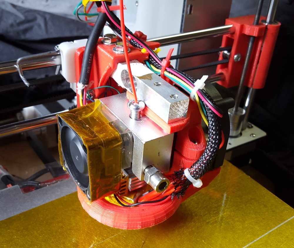
I've just completed a different Z-Probe design using a load cell (as in digital scales) to sense a nozzle hit on the bed.
The extruder hangs off the load cell beam, with some specially designed mounts.
I've created an Instructable that shows how I did it: [www.instructables.com]
It's pretty reliable and also quite sensitive.
|
Re: New Z-Probe uses Load Cell January 06, 2016 01:32AM |
Registered: 10 years ago Posts: 14 |
|
Re: New Z-Probe uses Load Cell January 07, 2016 12:21AM |
Registered: 10 years ago Posts: 14 |
|
Re: New Z-Probe uses Load Cell January 09, 2016 01:24AM |
Registered: 14 years ago Posts: 128 |
|
Re: New Z-Probe uses Load Cell February 19, 2016 08:54PM |
Registered: 10 years ago Posts: 14 |
Sorry for the slow reply.
Yes, exactly. The thing that can defeat the design, as with any probe that uses the actual hotend (e.g. FSRs) is the firmness of the hotend mounting springs (or other mechanical compliance factors like frame or rail bend) vs the force needed to squish the excess plastic around the nozzle.
The answers are probe when hot and keep your nozzle tip clean - both good ideas anyway.
On your specific question - yes. I set the actual value about half way in between when the plastic squishes and when the bed's springs start to move. Luckily the rig is sufficiently sensitive that it's not hard to find a good working value.
False triggering due to dynamic loads while the carriage is moving and the differences in trigger points at the three z-probe points, due to drag on the cables to the carriage also come into the picture.
Drift in the zero value over time (my measurements: 10-20% of the trigger value) also plays a part, hence issuing a recalibrate signal at the start of each probe cycle (manual or auto using gcode).
BTW: firmware code is at:
[github.com]
Instructables and Thingiverse links are in the posts above.
|
Anonymous User
Re: New Z-Probe uses Load Cell February 20, 2016 05:07AM |
Why make it simple when one can make it complicated ? A simple positioning switch, opening when pushed, not a micro switch which is not designed for accurate positionning, is far more accurate and simple than all these sensors. Look at what is done in the industry.
One can do it himself easily by modifying a micro switch. Don't forget, here we deal with rather crude machine, whose accuracy is in the 1/20th range when all is done properly, not microns !
Edited 1 time(s). Last edit at 02/20/2016 05:18AM by MKSA.
One can do it himself easily by modifying a micro switch. Don't forget, here we deal with rather crude machine, whose accuracy is in the 1/20th range when all is done properly, not microns !
Edited 1 time(s). Last edit at 02/20/2016 05:18AM by MKSA.
|
Re: New Z-Probe uses Load Cell March 11, 2016 01:11PM |
Registered: 11 years ago Posts: 471 |
|
Anonymous User
Re: New Z-Probe uses Load Cell March 13, 2016 05:29AM |
Quote
epicepee
MKSA: The advantage of load cells, FSRs, etc. is that they trigger with basically zero movement. This allows precise, rigid positioning, while still detecting force.
So can a simple switch. I modified a micro switch to just do that and it detects 0.01mm which far exceed 3D printer needs. No complication, no cost, no weight.
What about vibration ? The whole head about 300 gr. is hanging out of the load cell ! Tension from the filament, drift (heat, time ...) ... OK the signal is treated by the microcontroller to avoid these false trigger but I bet, they will happen !
Besides a printhead must be as light as possible.
And I don't think that hitting the nozzle against a hard surface is not good either.
As I said, a complex solution for a simple problem.
Edited 1 time(s). Last edit at 03/13/2016 05:44AM by MKSA.
|
Re: New Z-Probe uses Load Cell March 13, 2016 08:00PM |
Registered: 10 years ago Posts: 14 |
MKSA,
Different strokes!
I was trying to get rid of proxies (probes, etc) in the design, and therefore the microswitch solution, optical interrupters and hall effect probes didn't make the cut for my purposes.
FSRs are a conceptually a nice solution. Though I have heard several folks talk about practical difficulties in making this solution work. This idea came directly from the FSR thinking, looking for a way not to have the entire bed sitting on the load sensing element.
I agree with you that the carriage weight should be minimised and a downside in my design. Load cells are quite strong, though the extra leverage of the cantilevered print head could make for dynamic problems (not that I've noticed them. As for weight, the load cells are quite light, and I have a non-Bowden extruder, so I'm carrying a stepper motor on the carriage already.
As for grounding the print head - the trigger force is in the 10-30g (milli Newtons actually) range and straight up and down. I can't see this as a practical damage problem, though dribble on the hot end can be an accuracy issue if the print head is not hot enough when probing. These problems are shared by FSR designs which require hot end grounding, and thus my design is neither better or worse in this respect.
False triggering, absolutely! Resetting the probe before each measurement fixes all that - and for exactly the list of issues you note. Drift and time, however, are endemic to all settings made before a print run begins, if you are talking about dimensional changes through heat and dynamic loads.
Anyway, thanks for your critique of my design. A good discussion of the pros and cons sharpens the designer's mind.
|
Re: New Z-Probe uses Load Cell January 12, 2017 02:34AM |
Registered: 8 years ago Posts: 136 |
Hello Palmerr23,
i had the same idea of using a china-microscale-loadcell as z-probe and found your tutorial (which is realy great! Thank you!) when looking for a way to read the signals.
I use it in a delta printer with flying-bowden extruder. And use your electronic-setup with the HX-711 and your code on an aduino pro mini. (By the way why did you write not to use it? ("Arduino Nano V3.0 (5V, Atmega328) not the Arduino Pro Mini.")
The setup works very well on the desk. But I still have to Print a few parts before the first test in the printer.
The biggest problem will be to support the bowden, so it has no too big effect on the sensor. In the flying-bowden design there are narrow bending radius in the bowden at the edges of the printarea... I hope i can fix the problem only mechanical (without a second loadcell or the like).
Greetings
Junkie
|
Re: New Z-Probe uses Load Cell January 12, 2017 07:03PM |
Registered: 10 years ago Posts: 14 |
Junkie,
With the bowden, try making a solid attachment point on the carriage side of the load cell, so that the print head isn't wiggled around as it travels from side to side.
As for the Pro Mini, rather than the Nano - it was to remove confusion about 3.3V or 5V (the Pro Mini comes in both varieties).
My Reprap controlled is a Mega 2560 (5V), and the HX loadcell is OK with either.
Hope you do well with this approach. Most folks use Force Dependent Resistors with deltas as it's an easy install with a static build table.
Richard
|
Re: New Z-Probe uses Load Cell January 12, 2017 07:11PM |
Registered: 16 years ago Posts: 80 |
Sorry, only registered users may post in this forum.