Lead Screw usage for X and Y axes
Posted by tobben
|
Re: Lead Screw usage for X and Y axes April 23, 2016 02:02PM |
Registered: 11 years ago Posts: 5,780 |
Quote
tobben
Wow, thanks for all the response! You're right that a full realization of the mockup will be flimsy and fail in many ways. Constructing and measuring failure is what I do to learn.
I'm not trying to build a prototype that is a working printer, well designed working printers already exist and I have many of them. I'm trying to make as naïve a first prototype as I can, to be able to learn and measure exactly how much it fails. The question I ask myself when I start designing is "what do I wish would work?". Limiting work hours of over-engineering in this way allowed my previous project Clerck to go big fast. See blog for more Clerck.
It seems like a backward method to me. I generally start with designs that I'm pretty sure are going to work, then carve away at things after they have proven themselves, if ever. If you start with things that probably won't work, you spend a lot of extra time redesigning and printing them to get to a working state. By overbuilding from the start, I end up with something that works, so if I never get around to the tweaks and redesigns, I still have built something functional.
The little block I drew and linked took about 1 minute to "overengineer". It will take longer to print than the part you designed, but it is all but guaranteed to work. Eliminating unknowns where it is easy lets you focus development on areas where there are some significant unknowns, such as the viability of using the lead screw as a guide. If you build your design and find the results sloppy, with so much flex in so many parts, you don't know where to start to look for the source of problems and you'll be redesigning everything to make it more solid anyway. Once you've eliminated all the flexy bits, you'll be able to see what the lead screw/guide rail is actually able to do.
Ultra MegaMax Dominator 3D printer: [drmrehorst.blogspot.com]
|
Re: Lead Screw usage for X and Y axes April 23, 2016 02:35PM |
Registered: 8 years ago Posts: 10 |
|
Re: Lead Screw usage for X and Y axes April 24, 2016 05:30AM |
Registered: 10 years ago Posts: 401 |
Hi, yes of course we must design the testing procedures carefully so that we test one thing at a time. A simplistic prototype doesn't prevent isolating individual degrees of freedom and measuring them.
If your goal is to build one printer then you want to make it functional, of course. The mockup doesn't make sense unless you're interested in searching for the minimum unique parts counts and sizes that cheap lead screws could enable. Nobody commented on the mockup's inability to handle gravity? Anyways, I enjoy working this way
torbjornludvigsen.com
If your goal is to build one printer then you want to make it functional, of course. The mockup doesn't make sense unless you're interested in searching for the minimum unique parts counts and sizes that cheap lead screws could enable. Nobody commented on the mockup's inability to handle gravity? Anyways, I enjoy working this way

torbjornludvigsen.com
|
Re: Lead Screw usage for X and Y axes April 24, 2016 09:19AM |
Registered: 8 years ago Posts: 10 |
|
Re: Lead Screw usage for X and Y axes May 05, 2016 05:29PM |
Registered: 9 years ago Posts: 109 |
Have you made any headway on this, I have been working on mine for over a year swapping back and forth between belt drive and a SFU1204 ball screw installed for my X axis. Printer is a home built 450mm cubed usable size. It has been a super pain to get it setup the tolerances between the slides and the screw, they have to be perfect. You can tell when its not correct when the carriage travels to either end if the space isn't perfect the stepper has a hard time moving. I am using MassMind drivers LINK. 48VDC with Nema 23 motors
So one thing that has helped allot was gearing the stepper so you get more movement per rotation. So 1204 is 4mm per revolution, I doubled that with gearing for I get 8mm now. Max speed at 4mm was 40. So now I am 80, which is still allot slower than the 120 the belt drive can do.
So a couple ideas I still have on the plate is using two ball screws so I can get rid of the slides, really not sure if it will work but would be nice to lighten it up a little. I tried one slide and the ball screw and got some tilt deflection of the head.
I still want to try to gear it up more to see how fast I can get it, but that is more of a fun thing than useful. lol
|
Anonymous User
Re: Lead Screw usage for X and Y axes May 06, 2016 03:07AM |
Quote
AquaticsLive
Have you made any headway on this, I have been working on mine for over a year swapping back and forth between belt drive and a SFU1204 ball screw installed for my X axis. Printer is a home built 450mm cubed usable size. It has been a super pain to get it setup the tolerances between the slides and the screw, they have to be perfect. You can tell when its not correct when the carriage travels to either end if the space isn't perfect the stepper has a hard time moving. I am using MassMind drivers LINK. 48VDC with Nema 23 motors
So one thing that has helped allot was gearing the stepper so you get more movement per rotation. So 1204 is 4mm per revolution, I doubled that with gearing for I get 8mm now. Max speed at 4mm was 40. So now I am 80, which is still allot slower than the 120 the belt drive can do.
So a couple ideas I still have on the plate is using two ball screws so I can get rid of the slides, really not sure if it will work but would be nice to lighten it up a little. I tried one slide and the ball screw and got some tilt deflection of the head.
I still want to try to gear it up more to see how fast I can get it, but that is more of a fun thing than useful. lol
Quality linear guides and ball screws require a good design, rigid, well built frame and compliance to strict installation procedure. 90% of the "frame" designed here are not suitable and often junk and 90% of the "designers" don't follow or even don't understand how and why it has to be installed that way. And you don't learn these techniques on a general purpose forum. It is why most should stick to plain cheap chinese guides and regular Tr lead screws to limit the cost, pain, disappointment.
Well installed they will be good enough and produce acceptable quality. To replace them by high end guides will not improve much if the rest is substandard.
Edited 2 time(s). Last edit at 05/06/2016 05:39AM by MKSA.
|
Re: Lead Screw usage for X and Y axes May 06, 2016 08:04AM |
Registered: 11 years ago Posts: 5,780 |
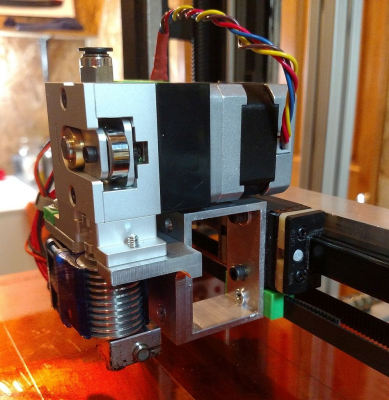
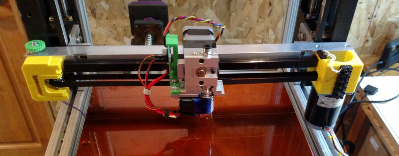
While I agree that the frame needs to be rigid to gain maximum benefit from linear guides, they have advantages that apply regardless of frame rigidity. For one thing, you can usually use just one linear guide in the X axis and make it more compact. It is very easy to design an extruder carriage to fit the bearing block.
In the Y axis of i3 type machines, the addition of a support to the bottom of the frame would allow installation of a pair of linear guides. The support could be an aluminum plate, maybe even a piece of wood (I wouldn't recommend it, but people use all sorts of crazy materials to build printers) if you're careful with it. In a small machine, one might be able to get away with a single, large linear guide for the Y axis. In a small coreXY or SLA type machine you might be able to use a single linear guide in the Z axis, again, depending on sizes and the rest of the construction.
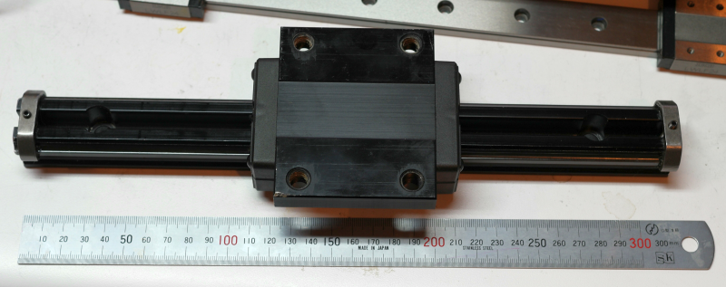
Installing a single linear guide isn't difficult- drill a bunch of holes and screw it down to a flat surface such as a plate or tube. Installing a pair of them in parallel takes a little more care but isn't very hard to do. You screw the first rail down then use the bearing blocks and the undercarriage (which is securely attached to the bearing blocks) to position the the second guide parallel to the first one. It may take a little messing around, but it's actually easier than guaranteeing that round rails are parallel to each other because the flat surface they are screwed to eliminates one of the degrees of freedom. Trying to couple a linear guide to a high quality lead screw is a bit more work and best accomplished if you have access to a milling machine, but it's not entirely necessary. You can buy lead screws that come with motor mounts and bearing blocks and the process for installing them isn't much different than setting up a second linear guide.
Good surplus Japanese, German, and Swiss made linear guides show up on ebay all the time and can sometimes be purchased for less than the cost of new, lower quality, Chinese made guides. The last three I bought were THK and NSK products, one of which was unused old-stock, and cost $35 each, shipped. For 3D printer use, about the only spec you have to worry about is whether the rail is long enough (you can cut them shorter using a cut-off wheel on a grinder).
Edited 1 time(s). Last edit at 05/06/2016 08:09AM by the_digital_dentist.
Ultra MegaMax Dominator 3D printer: [drmrehorst.blogspot.com]
|
Anonymous User
Re: Lead Screw usage for X and Y axes May 06, 2016 11:51AM |
Quote
the_digital_dentist
While I agree that the frame needs to be rigid to gain maximum benefit from linear guides, they have advantages that apply regardless of frame rigidity. For one thing, you can usually use just one linear guide in the X axis and make it more compact. It is very easy to design an extruder carriage to fit the bearing block.
....
OK but I am speaking about the average Joe, who seems to have no understanding about the fundamentals and expect that these will make miracle.
You just mentioned "degree of freedom", how many do you think understand what it means ? How many speak in "micron" without having a clue of what it is ? Worse, too many don't even want to learn, thinking that by "experimenting", they will succeed.
Besides, if they start buying these guides and screws on fleabay, the prices will go up and harm the few who can really use them

Note that I took an other approach, a challenge indeed, get the most of these Chinese junk parts and I am quite surprised by the results when I compare my PLA prints (Heavily modified Geetech Prusa I3 at 120mm/s) with what I can see here and on thingiverse.
Edited 1 time(s). Last edit at 05/06/2016 12:06PM by MKSA.
|
Re: Lead Screw usage for X and Y axes May 06, 2016 12:56PM |
Registered: 10 years ago Posts: 9 |
Quote
MKSA
OK but I am speaking about the average Joe, who seems to have no understanding about the fundamentals and expect that these will make miracle.
In my experience, "average Joe's" buy commercial machines and don't frequent places like reprap and other internet sources. They are only interested in the end product not how it is made. In one way or another everyone in this hobby of building 3d printers comes from a drive to learn. When I first watched a youtube 3d printing video I knew nothing of this technology. Five minutes later I had two books on the topic coming from my library with a purchase order for more. Few are already knowledgeable given background experience, more are taking the first step and have a lot to learn. I for one learn by reading / observing. Others learn by trying / failing neither is wrong so long as you learn.
Quote
MKSA
You just mentioned "degree of freedom", how many do you think understand what it means ?
I would say there are more of us with engineering / drafting / design backgrounds then one would first assume based on posts alone, but I digress. If four out of the ten who do not understand the terminology take the time to research it and come back to better understand the discussion. We have succeed! To quote my old teacher: " The student must fist want to learn before they can be taught. "
|
Re: Lead Screw usage for X and Y axes May 09, 2016 05:03AM |
Registered: 8 years ago Posts: 310 |
haven't been around for a few months, my project is on hold as I'm moving home, in the meantime I have some revision made to the design to give it maximum rigidity and speed that I can come up with myself, someone else may do a better design than me, I will post up again when I get to build the machine and have it up and running, again, the design will remain using leadscrews only 
Edited 1 time(s). Last edit at 05/09/2016 05:04AM by deaconfrost.

Edited 1 time(s). Last edit at 05/09/2016 05:04AM by deaconfrost.
|
Re: Lead Screw usage for X and Y axes September 01, 2016 06:30PM |
Registered: 8 years ago Posts: 310 |
|
Re: Lead Screw usage for X and Y axes September 02, 2016 03:29AM |
Registered: 10 years ago Posts: 401 |
|
Re: Lead Screw usage for X and Y axes September 02, 2016 02:21PM |
Registered: 8 years ago Posts: 310 |
cut the leadscrews today, some effort to cut them by hand, need a break, all ready to go for electronics 
not sure if I do it tomorrow, want a day off on my birthday, but then again, it can be a great birthday to have it up and running
boards are tested and ran very well, all set to plug and play.... I might just do it tomorrow if not I will on sunday

not sure if I do it tomorrow, want a day off on my birthday, but then again, it can be a great birthday to have it up and running

boards are tested and ran very well, all set to plug and play.... I might just do it tomorrow if not I will on sunday

|
Re: Lead Screw usage for X and Y axes September 03, 2016 02:57PM |
Registered: 8 years ago Posts: 310 |
mounted the motors on and tested all axis, the old folgertech nema 17 48mm don't seem to perform anywhere as good as the motech ones, at same current, the motech was able to travel at 200mm/s where as the folgertech skips at 150mm/s
the 2 32mm long nema17 was well able to move the big bed up and down with no problem, it has a fair bit of weight as Im using a 10mm thick 500 x 500 acrylic plate
Edited 2 time(s). Last edit at 09/03/2016 03:00PM by deaconfrost.
the 2 32mm long nema17 was well able to move the big bed up and down with no problem, it has a fair bit of weight as Im using a 10mm thick 500 x 500 acrylic plate
Edited 2 time(s). Last edit at 09/03/2016 03:00PM by deaconfrost.
|
Re: Lead Screw usage for X and Y axes September 04, 2016 03:12AM |
Registered: 10 years ago Posts: 401 |
Thats interesting. What are the specs of the two different stepper motors (the Motech and the Folgertech one)?
I've noticed surprisingly high inductance in some shorter Folgertech 34mm Nema 17 motors before (see comments 14, 15 and 16 here: [opensourceecology.org]).
Are the axes much more noisy than belt-driven axes?
torbjornludvigsen.com
I've noticed surprisingly high inductance in some shorter Folgertech 34mm Nema 17 motors before (see comments 14, 15 and 16 here: [opensourceecology.org]).
Are the axes much more noisy than belt-driven axes?
torbjornludvigsen.com
|
Re: Lead Screw usage for X and Y axes September 04, 2016 03:25AM |
Registered: 10 years ago Posts: 14,672 |
Quote
tobben
Thats interesting. What are the specs of the two different stepper motors (the Motech and the Folgertech one)?
I've noticed surprisingly high inductance in some shorter Folgertech 34mm Nema 17 motors before (see comments 14, 15 and 16 here: [opensourceecology.org]).
Are the axes much more noisy than belt-driven axes?
From what I have read, Folgertech used to supply 12V 0.4A stepper motors with their kits, which is a poor choice for a 3D printer - especially if you want high speed. I think they may have switched to a different motor spec in their more recent kits.
Edited 1 time(s). Last edit at 09/04/2016 03:27AM by dc42.
Large delta printer [miscsolutions.wordpress.com], E3D tool changer, Robotdigg SCARA printer, Crane Quad and Ormerod
Disclosure: I design Duet electronics and work on RepRapFirmware, [duet3d.com].
|
Re: Lead Screw usage for X and Y axes September 04, 2016 06:24AM |
Registered: 8 years ago Posts: 310 |
have no idea on the spec of the folgertech motor, it doesn't give any info on the back nor their website, its from the acrylic frame i3, so it is very old
there's virtual no noise from the screw and nut, all the noise you hear is from the motor and the rods and bearings, I'm using delrin anti backlash block, the delrin nut has no sound at all when turning the screw in it
some vibration noise from the Y axis probably due to the folgertech motor
Edited 1 time(s). Last edit at 09/04/2016 06:26AM by deaconfrost.
|
Re: Lead Screw usage for X and Y axes September 04, 2016 08:50AM |
Registered: 10 years ago Posts: 401 |
|
Re: Lead Screw usage for X and Y axes September 04, 2016 03:15PM |
Registered: 8 years ago Posts: 310 |
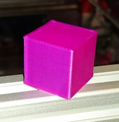
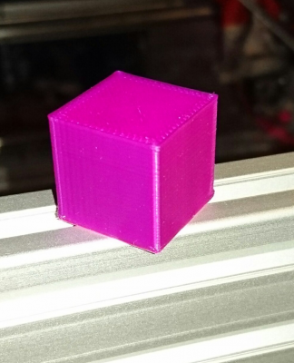
all up and running, using the v6 instead of chimera, one thermistor die out of the blue, don't have a spare and dont want to take it from the v6
0.25mm layer height
100mm/s Print
100mm/s travel
20mm/s first layer
30mm/s outer perimeter
60mm/s inner perimeter
80mm/s infill
60mm/s skin infill
it was printed with 0 infill actually
bridging very well
so far so good
looking to print something big but doesn't use a lot of filament, running very low
Edited 1 time(s). Last edit at 09/04/2016 04:57PM by deaconfrost.
|
Re: Lead Screw usage for X and Y axes September 05, 2016 02:55AM |
Registered: 10 years ago Posts: 401 |
Looks like stunning layer consistency from what I can see =) Congrats!
What do you think about the cornering? They look a bit on the round side on the pictures. Do they feel sharp in your hand?
torbjornludvigsen.com
What do you think about the cornering? They look a bit on the round side on the pictures. Do they feel sharp in your hand?
torbjornludvigsen.com
|
Re: Lead Screw usage for X and Y axes September 05, 2016 03:34AM |
Registered: 8 years ago Posts: 310 |
|
Re: Lead Screw usage for X and Y axes September 05, 2016 07:53AM |
Registered: 10 years ago Posts: 401 |
Nice! What is your aim and philosophy with the design? Would you say you have prioritized print quality over price? Have you prioritized ease of assembly, low maintenance or other aspects highly?
I find it interesting that you use only 1 smooth rod along each lead screw since I like to prioritize low parts counts.
Edited 1 time(s). Last edit at 09/05/2016 07:57AM by tobben.
torbjornludvigsen.com
I find it interesting that you use only 1 smooth rod along each lead screw since I like to prioritize low parts counts.
Edited 1 time(s). Last edit at 09/05/2016 07:57AM by tobben.
torbjornludvigsen.com
|
Re: Lead Screw usage for X and Y axes September 05, 2016 10:46AM |
Registered: 8 years ago Posts: 310 |
I aim for print quality and price 
next I look in to ease of assembly, although there aren't much more it can simplify
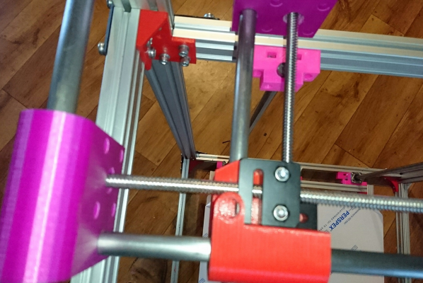
with the strength of the 12mm rods plus a solid design mounting, there isn't really need for 2 rods, as you can see from the test print, theres absolutely no chance of the guide shifting with those 12mm rods unless you let them loose
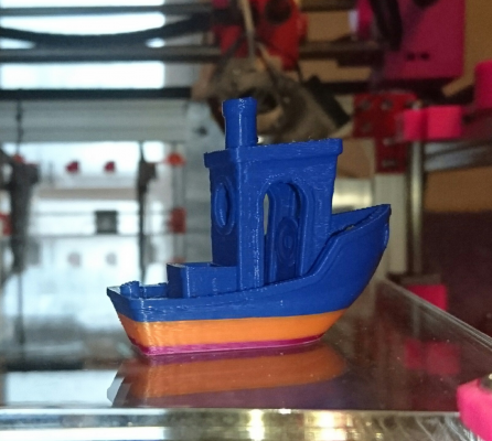
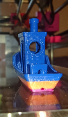
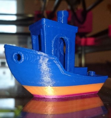
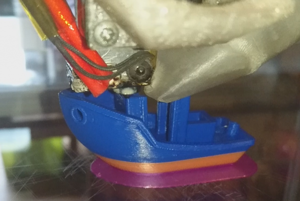
I'm printing the 3dbenchy at the minute, I will post up when its done, print setting as what 3dbenchy listed
maintenance should be fairly low once I add the servo probe, I'm not a huge fan on other sensors, as the proximity will not work since I don't have a metal plate, capacity was rather inconsistent and the sensor actually stopped working suddenly on the i3, lucky I happened to be looking at it, stopped it just as the nozzle made contact to the bed before it gets too far.
Edited 2 time(s). Last edit at 09/05/2016 11:42AM by deaconfrost.

next I look in to ease of assembly, although there aren't much more it can simplify
with the strength of the 12mm rods plus a solid design mounting, there isn't really need for 2 rods, as you can see from the test print, theres absolutely no chance of the guide shifting with those 12mm rods unless you let them loose

I'm printing the 3dbenchy at the minute, I will post up when its done, print setting as what 3dbenchy listed
maintenance should be fairly low once I add the servo probe, I'm not a huge fan on other sensors, as the proximity will not work since I don't have a metal plate, capacity was rather inconsistent and the sensor actually stopped working suddenly on the i3, lucky I happened to be looking at it, stopped it just as the nozzle made contact to the bed before it gets too far.
Edited 2 time(s). Last edit at 09/05/2016 11:42AM by deaconfrost.
|
Re: Lead Screw usage for X and Y axes September 05, 2016 12:09PM |
Registered: 8 years ago Posts: 310 |
Could have been better with lower nozzle temp and retract on layer change, Cura in Repetier didnt have the option
|
Re: Lead Screw usage for X and Y axes September 05, 2016 03:01PM |
Registered: 10 years ago Posts: 401 |
I see the overheating you mention in some places, but once again very consistent in putting one layer exactly on top of the previous one. 
Do you use 12 mm rods for the Z axis as well?
torbjornludvigsen.com

Do you use 12 mm rods for the Z axis as well?
torbjornludvigsen.com
|
Re: Lead Screw usage for X and Y axes September 05, 2016 03:31PM |
Registered: 8 years ago Posts: 310 |
yup, all 12mm rods, bed is big and heavy so 4 12mm rods to keep it in place, again very solid, doesn't go anywhere other than up and down 
the most fun part I had was watching the first layer from underneath, printer is so big I can just kinda get under the bed and look at it print, on first layer I have a around 650mm space to move about
running low on filament and cash, hopefully I get some more plastic soon and do a big print
Edited 3 time(s). Last edit at 09/05/2016 03:53PM by deaconfrost.

the most fun part I had was watching the first layer from underneath, printer is so big I can just kinda get under the bed and look at it print, on first layer I have a around 650mm space to move about

running low on filament and cash, hopefully I get some more plastic soon and do a big print
Edited 3 time(s). Last edit at 09/05/2016 03:53PM by deaconfrost.
|
Re: Lead Screw usage for X and Y axes September 06, 2016 04:00AM |
Registered: 10 years ago Posts: 401 |
Cool! Yeah, big printers extrude lots of plastic. I've seen people automate material costs calculation, so they don't accidentally print expensive things 
12 mm rods are quite expensive where I live. How did you source them? Are they chromed?
torbjornludvigsen.com

12 mm rods are quite expensive where I live. How did you source them? Are they chromed?
torbjornludvigsen.com
|
Re: Lead Screw usage for X and Y axes September 06, 2016 05:58AM |
Registered: 8 years ago Posts: 310 |
I got mine from a local engineering place, these are not chrome, but I'm looking to put it up on kickstarter and there will be option for chrome then, but it is a good idea to run the linear bearings with added lubrication, once theres a layer of grease on them it wouldn't matter, there be optional enclosure as well, I have sourced a manufacturer for acrylic sheets on various thickness, I will be designing another one to be built with aluminium plate, I have sourced a supplier for that as well, then I will do some delta 
I have a fair idea of cost on filament by the meters showing in repetier after slicing, as its roughly around 330m for a kg of pla and a bit more for abs
Edited 2 time(s). Last edit at 09/06/2016 06:03AM by deaconfrost.

I have a fair idea of cost on filament by the meters showing in repetier after slicing, as its roughly around 330m for a kg of pla and a bit more for abs
Edited 2 time(s). Last edit at 09/06/2016 06:03AM by deaconfrost.
|
Re: Lead Screw usage for X and Y axes September 17, 2016 02:48PM |
Registered: 8 years ago Posts: 310 |
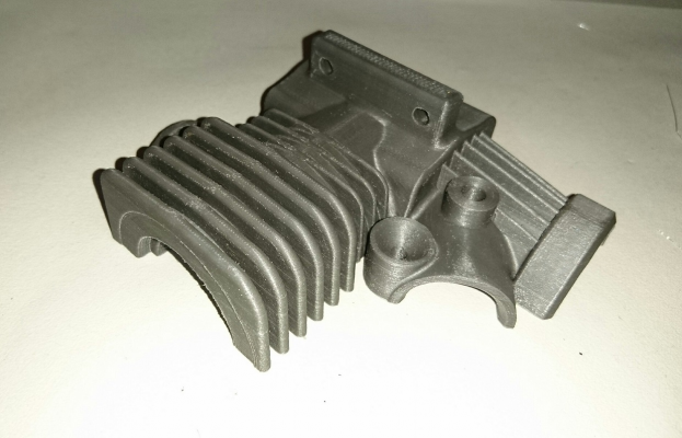
just one more to show its ability
107.2mm x 96.64mm x 34.22mm
Printed at 50 micron without support
Edited 2 time(s). Last edit at 09/17/2016 02:49PM by deaconfrost.
107.2mm x 96.64mm x 34.22mm
Printed at 50 micron without support
Edited 2 time(s). Last edit at 09/17/2016 02:49PM by deaconfrost.
|
Re: Lead Screw usage for X and Y axes September 17, 2016 02:57PM |
Registered: 10 years ago Posts: 401 |
Sorry, only registered users may post in this forum.
