Lead Screw usage for X and Y axes
Posted by tobben
|
Re: Lead Screw usage for X and Y axes September 17, 2016 03:08PM |
Registered: 8 years ago Posts: 310 |
thanks
I'm very please with the outcome, there has been many revision and a very long time designing and testing different build
I'll be revising the appearance of the printer but keeping all mechanical exactly the same, and will be produced in transparent red PETG then treat with z-poxy
Edited 2 time(s). Last edit at 09/17/2016 03:11PM by deaconfrost.
|
Re: Lead Screw usage for X and Y axes September 22, 2016 09:03PM |
Registered: 11 years ago Posts: 5,780 |
Update: after modifying the electronics in my printer I was doing some extruder tuning and found that the infill lines weren't evenly spaced- I was printing at 95% infill with the lines at 45 degrees. Every other fill line had a wider gap. Since the lines were at 45 degrees, I couldn't determine of the problem was coming from the X axis, the Y axis, or both. So I resliced with the infill lines oriented parallel to the axes and printed again. The result appears below.
The bottom half of the image is the X axis parallel lines with spacing determined by the ball screw in the Y axis. The upper half is the Y axis parallel lines with spacing determined by the belt driven X axis. I think its obvious where the problem (small as it is) lies...
Ultra MegaMax Dominator 3D printer: [drmrehorst.blogspot.com]
The bottom half of the image is the X axis parallel lines with spacing determined by the ball screw in the Y axis. The upper half is the Y axis parallel lines with spacing determined by the belt driven X axis. I think its obvious where the problem (small as it is) lies...

Ultra MegaMax Dominator 3D printer: [drmrehorst.blogspot.com]
|
Re: Lead Screw usage for X and Y axes September 23, 2016 02:28AM |
Registered: 10 years ago Posts: 401 |
A little uneven mm/degree on the belt driven axis it seems?
Edited 1 time(s). Last edit at 09/23/2016 02:29AM by tobben.
torbjornludvigsen.com
Edited 1 time(s). Last edit at 09/23/2016 02:29AM by tobben.
torbjornludvigsen.com
|
Re: Lead Screw usage for X and Y axes December 20, 2017 02:39PM |
Registered: 6 years ago Posts: 7 |
I know this is an older thread but I just came across it and wanted to thank everyone who participated in the discussion. I decided to build an “all leadscrew” cube style printer a few months ago and I was surprised to realize that there isn’t/wasn’t a lot of info/discussion out there on similar projects. I suspect this is because nearly every other printer architecture is easier to build, cheaper to make, and performs better! So I wasn’t setting out to build the most amazing printer ever it was more about the project itself and having fun with it.
Anyway, my machine is still in the design iteration and construction phase and likely won’t be printing for another month or so but some top level design features are:
- It’s relatively large with a print envelope of roughly 480mm deep x 440mm wide by 550mm high
- Cube design with heavy duty 3030 aluminum profile
- Runs on 24V (except for the heated bed) with a DuetWifi controller and PanelDue touchscreen for the user interface
- Extruder (24V E3D V6) is fixed in Z and moves in XY via a single 2.4A 0.9deg NEMA17 motor on each axis with each motor/belt driving two 8mm diameter 12mm lead leadscrews (with 8mm linear rods adjacent to each leadscrew). The baseline design has a 40T drive pulley on each motor and 20T pullleys on the leadscrews but I can easily change the motor drive pulled out for a 30T or 20T.
- Heated bed moves in Z via a single motor/belt driving four 8mm diameter 4mm lead leadscrews (and again I have four 8mm linear rods adjacent to each leadscrew). Currently I’m using the same motor as I’m using for XY but depending upon how heavy the bed comes in I may have to upgrade the Z motor to a NEMA23
- Heating the bed accomplished by a 1200W 110V
- All belts are closed
- All steppers are actively cooled with a printed motor housing bracket/manifold and 40mm 24V fan
A few quick thoughts:
- I calculated that I should be able to get good speed out of my XY axis given I’m running the motors at 24V, they have high current capability of 2.4A, I’m using 12mm lead leadscrews, and I have the ability to vary the gear ratio from 1:1 to 2:1 in 0.5 increments.
- I bought a lot of my parts from Banggood and AliExpress. Quality varies wildly (and even in the same order) as does shipping time so my advice would be, since the stuff is so cheap, to order much more than what you need. I typically order 2x what I need at minimum and/or order the same part from multiple different sellers. For dimension critical parts you’ll want to cherry pick and have a big lot to pull from. For drive pulleys specifically order 5x what you need because 75% of what you receive will have misdrilled features, out of position holes, or just have knicks/dings/damage.
- I spent the money to get good rods, linear bearings, leadscrews, and controller/touchscreen. The frame is also custom length/drilled profile from Misumi but that’s really because I didn’t want to keep bothering my friend who has a mill and the profile isn’t anywhere near as expensive as most of the other misumi.
Anyway, if anyone is interested I can provide more info but either way this is a great thread!
|
Re: Lead Screw usage for X and Y axes December 22, 2017 12:14AM |
Registered: 6 years ago Posts: 1,007 |
|
Re: Lead Screw usage for X and Y axes December 30, 2017 12:49AM |
Registered: 6 years ago Posts: 93 |
I run a leadscrew driven i3 homebuilt. It took some work to get the openbuild's screws straight enough, but I stuck with them for the Delrin nuts.
What I wasn't prepared for is artifacts coming out of the woodwork--turned out to be dirty power from the mains, and an Islatrol filter solved it...never saw such a thing with the belt driven machine using the same board/drivers/Meanwell (24V).
With 8x8 screws on x,y it would do 100mm/s easily, but I'm an old duffer, and usually print at 50 anyway.
Alas, I'm currently looking to refit the machine with 9mm belts. The torque moments from the screw keep loosening up the v-wheel eccentrics, and I have to readjust frequently--not what you'd expect from a sturdy machine, eh? Also in using extrusion, you cannot center the motive force, so it's always going to work against precision and longevity.
I've come to understand my mistakes with belts and the 2mm artifacts I could not get rid of--tensioning at installation is fine, re-tensioning after a few hundred hours of printing is not. Throw out the belts and restring the machine, because that slack is your pitch changing, and the teeth will 'snap' onto the sprocket teeth. Lesson learned.
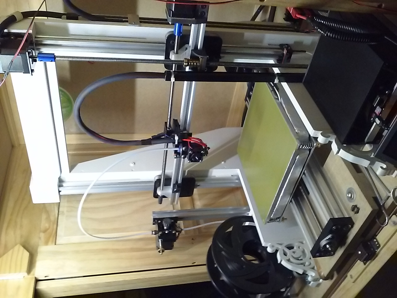
Anyway, a pic before it's mamed. (lol)
What I wasn't prepared for is artifacts coming out of the woodwork--turned out to be dirty power from the mains, and an Islatrol filter solved it...never saw such a thing with the belt driven machine using the same board/drivers/Meanwell (24V).
With 8x8 screws on x,y it would do 100mm/s easily, but I'm an old duffer, and usually print at 50 anyway.
Alas, I'm currently looking to refit the machine with 9mm belts. The torque moments from the screw keep loosening up the v-wheel eccentrics, and I have to readjust frequently--not what you'd expect from a sturdy machine, eh? Also in using extrusion, you cannot center the motive force, so it's always going to work against precision and longevity.
I've come to understand my mistakes with belts and the 2mm artifacts I could not get rid of--tensioning at installation is fine, re-tensioning after a few hundred hours of printing is not. Throw out the belts and restring the machine, because that slack is your pitch changing, and the teeth will 'snap' onto the sprocket teeth. Lesson learned.
Anyway, a pic before it's mamed. (lol)
|
Re: Lead Screw usage for X and Y axes November 12, 2019 06:37AM |
Registered: 9 years ago Posts: 10 |
Hi
I have Made a printer using a 6 mm ball screw pitch 2.5
And iT works well but slow
The work area is 120x120x200 mm
An i used sneeberger guideways
IT is all overkil but My goal was to creatie a xy stage thats close to perfect
To test the effect of different print heads
The raison it prints slow is that the motors cant keep up the rpm
And its PowerD by a Rambo on 24 v but iT can not generale the steps fast
So for my version 2
- 32 bit printer board
- 12.5 mm pitch 8mm eichenberger lead crew plastic nut
The nut wil be cooled using oil provided big a gear pump
I use white oil fda approved
-going to use mks 42 servo as Motors they Kost 30 € now so way not
So I don’t lose steps and find the point we’re the board cant keep up
|
Re: Lead Screw usage for X and Y axes November 13, 2019 01:21AM |
Registered: 10 years ago Posts: 14,672 |
To get high motor speeds, it's also important to use low inductance motors. You can use the motor EMF calculator at reprapfirmware.org to estimate the highest speed achievable before torque drops off and the motors become noisier.
Large delta printer [miscsolutions.wordpress.com], E3D tool changer, Robotdigg SCARA printer, Crane Quad and Ormerod
Disclosure: I design Duet electronics and work on RepRapFirmware, [duet3d.com].
Large delta printer [miscsolutions.wordpress.com], E3D tool changer, Robotdigg SCARA printer, Crane Quad and Ormerod
Disclosure: I design Duet electronics and work on RepRapFirmware, [duet3d.com].
|
Re: Lead Screw usage for X and Y axes November 14, 2019 04:40AM |
Registered: 9 years ago Posts: 10 |
Hi if u wand long life of the lead screws good lubrication is the key
If u can’t afford ballscrews best is have the led screw in an oil bath
Yes it’s harder to make but it’s easy to get 14 mm Multi Start 8mm leads-screws
Optional u van use Igus leadscrews ( eichen Berger)
Kost of one Meter is 50€ and nuts are about 15€
I am making now a printer using 12.5 pitch 8 mm igus
I dot wand the Pom nut to get warm on long prints so lubricate the nut
Using white oil (fda safe) and a gear pump
And the oil in the nut will eliminate backlash I hope
My current printer is using 2.5 mm pitch ball-screws
So the Printer is slow
And i am going to use the MKS 42 servo as Motor for xy and MKS SGEN 32 Bit board
I understand the longing for cheap parts but in my opinion misprints are more expensive
And for lead-screws u wand a stif frame
|
Re: Lead Screw usage for X and Y axes November 14, 2019 04:43AM |
Registered: 9 years ago Posts: 10 |
|
Re: Lead Screw usage for X and Y axes November 14, 2019 08:10AM |
Registered: 6 years ago Posts: 1,007 |
Quote
snowleopard
...
I am making now a printer using 12.5 pitch 8 mm igus
I dot wand the Pom nut to get warm on long prints so lubricate the nut
Using white oil (fda safe) and a gear pump
And the oil in the nut will eliminate backlash I hope
....
Are you serious ??????
"A comical prototype doesn't mean a dumb idea is possible" (Thunderf00t)
|
Re: Lead Screw usage for X and Y axes December 11, 2019 04:34AM |
Registered: 6 years ago Posts: 3 |

Sorry, only registered users may post in this forum.