kinematics of bed plate adjustment
Posted by rmlrn
|
kinematics of bed plate adjustment March 14, 2016 10:15AM |
Registered: 9 years ago Posts: 33 |
I'm thinking about how to make my bed plate adjustable, and the typical method (bolt fixed to build plate threaded through the base plate) doesn't sit right with me. It seems like making more than tiny adjustments like that is asking to bind the screws/bend the plate.
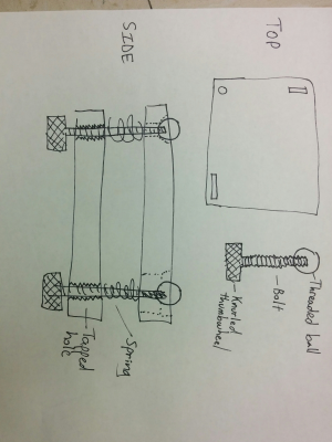
I've been looking at optical mirror mounts for inspiration, and they seem to have one end of the adjustment screw free to move. Here's a sketch of my current idea:
Basically I replace the fixed bolts with ball-ended bolts, which are captured through cavities in the build plate (circular at the one corner, horizontal/vertical slots at the others. As threaded balls are available pretty cheaply, this seems like an easy improvement.
The drawback is I lose a little printable surface at the edges, but if I use steel inserts in the build plate I could use extremely strong springs which should help prevent any unwanted movement.
Has anyone seen this tried before? Any obvious problems I'm missing?
|
Re: kinematics of bed plate adjustment March 14, 2016 09:01PM |
Registered: 11 years ago Posts: 5,780 |
I haven't used balls, but I use countersunk flat-head screws for the same effect. You want the bed to be able to pivot at the screws without generating any bending forces.
In my printer the bed moves in the Y axis which makes secure mounting of the bed plate extremely important because of all the mass that's gets thrown back and forth when the bed reverses direction. If the screws are free to wobble in their holes the bed will shift and print layer registration and surface quality will suffer. You're showing screws going into threaded holes in the undercarriage. Screws normally have quite a bit of play inside threaded holes- just try wiggling a screw inside a nut. I fixed that problem by mounting 3/4" thick teflon blocks on the undercarriage and drilling undersized pilot holes in them, then driving the screws directly into the teflon. It grips the screws tightly but allows vertical adjustment without allowing the screws to wiggle at all. I attached thumb wheels to the screws so I could adjust them from the under side of the bed without tools.
You can see the design with pictures and drawings here: [www.instructables.com]
While you're thinking about all this, I suggest that you use a 3 point leveling system and not a 4 point system. 4 point levelers actually bend the bed/undercarriage, while a 3 point system will level it without bending it.
Slots will have to be cut and fit to the screws very precisely to prevent extraneous motion. I assume you are doing that to allow the plate to expand when heated. I recently did some tests of the flatness of the bed plate when it's at room temp and heated. I redesigned the undercarriage to eliminate lateral stress on the plate caused by expansion against the leveler screws and found that that lateral force doesn't seem to affect the flexing of the plate much (I use 1/4" cast tooling plate for the bed). Unless you're making a very large bed that will expand a lot or unless you're using very thin, flexible material for the bed, you probably don't need the slots.
Edited 1 time(s). Last edit at 03/14/2016 09:06PM by the_digital_dentist.
Ultra MegaMax Dominator 3D printer: [drmrehorst.blogspot.com]
|
Anonymous User
Re: kinematics of bed plate adjustment March 15, 2016 06:47AM |
You got it right but why it isn't done that way ?
Simple, a bed has four corners so four adjusting point at each corner.
Yes but a plane is defined by three points no ?
Pffff, don't bother with your "therory", we are practical here ! We try, then try, then try ... See all the issues about bed level and leveling.
Fact is, as most beds are somewhat flexible and not flat, three screws will after trial and errors lead to the plane they form to be // to the X Y axis and the fourth will "correct" the fourth to be in that plane. Et voila ! You align and "flatten" your bed. Almost ! But in fact enough most of the time here.
If you have a rigid bed, then, you will be driven crazy adjusting these 4 screws.
The DD approach is the right one, implementation can vary but to justify it, all the rest of the machine must be well designed and built.
Edited 1 time(s). Last edit at 03/15/2016 06:49AM by MKSA.
Simple, a bed has four corners so four adjusting point at each corner.
Yes but a plane is defined by three points no ?
Pffff, don't bother with your "therory", we are practical here !
 We try, then try, then try ... See all the issues about bed level and leveling.
Fact is, as most beds are somewhat flexible and not flat, three screws will after trial and errors lead to the plane they form to be // to the X Y axis and the fourth will "correct" the fourth to be in that plane. Et voila ! You align and "flatten" your bed. Almost ! But in fact enough most of the time here.
If you have a rigid bed, then, you will be driven crazy adjusting these 4 screws.
The DD approach is the right one, implementation can vary but to justify it, all the rest of the machine must be well designed and built.
Edited 1 time(s). Last edit at 03/15/2016 06:49AM by MKSA.
|
Re: kinematics of bed plate adjustment March 15, 2016 09:10AM |
Registered: 9 years ago Posts: 33 |
Thanks guys for the comments but I'm a bit confused, my drawing has 3 adjustment points not 4, in total agreement with you about that!
My bed is 3/8" cast jig plate and only 200x200mm, so I'm pretty sure it rigid enough to stay flat only supported at 3 corners.
I'm more concerned about potential warping forces due to overconstraining the system, even with 3 just screws.
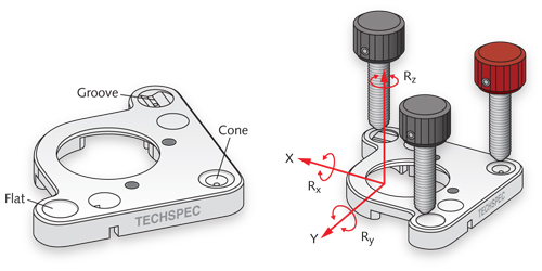
A ball in a circular cavity at one corner provides a fixed point contact, and a ball in a slot at another corner provides a line contact which fixes rotation around that point.
At this stage, the assembly is fulled constrained - really the adjustment at the 3rd corner should be free to float in both dimensions, but I can't figure out how to do that while still having the spring pushing the bed away from the support.
This diagram is probably clearer than my sketch:
|
Re: kinematics of bed plate adjustment March 15, 2016 12:39PM |
Registered: 11 years ago Posts: 5,780 |
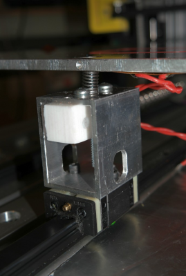
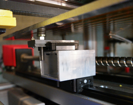
Here's what I did for a recent test:
Each leveling screw rides on its own bearing block and is free to follow expansion of the plate when heated.
Edited 1 time(s). Last edit at 03/15/2016 12:44PM by the_digital_dentist.
Ultra MegaMax Dominator 3D printer: [drmrehorst.blogspot.com]
Each leveling screw rides on its own bearing block and is free to follow expansion of the plate when heated.
Edited 1 time(s). Last edit at 03/15/2016 12:44PM by the_digital_dentist.
Ultra MegaMax Dominator 3D printer: [drmrehorst.blogspot.com]
|
Anonymous User
Re: kinematics of bed plate adjustment March 15, 2016 03:49PM |
Quote
rmlrn
Thanks guys for the comments but I'm a bit confused, my drawing has 3 adjustment points not 4, in total agreement with you about that!
My bed is 3/8" cast jig plate and only 200x200mm, so I'm pretty sure it rigid enough to stay flat only supported at 3 corners.
I'm more concerned about potential warping forces due to overconstraining the system, even with 3 just screws.
A ball in a circular cavity at one corner provides a fixed point contact, and a ball in a slot at another corner provides a line contact which fixes rotation around that point.
At this stage, the assembly is fulled constrained - really the adjustment at the 3rd corner should be free to float in both dimensions, but I can't figure out how to do that while still having the spring pushing the bed away from the support.
This diagram is probably clearer than my sketch:
I saw, but I was kidding about the way of reasoning which lead to the current 4 screws at each corner set up instead of a three points system and all the misunderstanding I read on the forum.
To reason in term of degree of freedom, constraints etc... is indeed the way to go.
On the other hand, we are not dealing with CNC, or optical system here. SO careful not to overdo it.
Sorry, only registered users may post in this forum.
