Comparing worm gear drives- any ideas?
Posted by the_digital_dentist
|
Comparing worm gear drives- any ideas? April 16, 2018 10:01AM |
Registered: 11 years ago Posts: 5,780 |
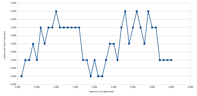
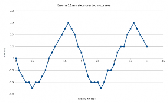
I used an OnDrives Rino 30:1 worm gear drive in UMMD's belt lifted Z axis. It provided lifting ability, increased resolution and prevented the bed from dropping when motor power was cut. It was an expensive part so I looked for a way to make a lower cost drive. I got a 40:1 worm gear set from China, added a couple bearings and a motor and then ran some tests on it. The machine was set up with 2 mm pitch GT2 belt, 40 tooth drive pulleys, a 200 step/rev motor, and 16:1 ustepping for 1600 usteps/mm or 100 full steps per mm. I clamped a digital gauge to the printer's frame and brought the bed up to the probe, then stepped the bed position in 0.1 mm increments using the jog function on the LCD panel over a range of 4 mm (two complete revs of the worm gear). The basic specs of the gauge are accuracy +/- 0.02 mm and precision +/- 0.01 mm. Results:
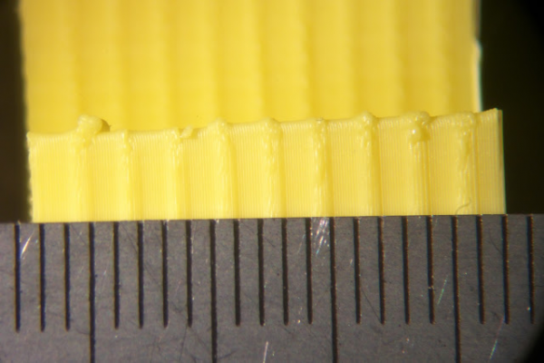
Then I made a test print in 100 um layers and it looked as expected- ribs every 2 mm in Z, making it just about useless for 3D printing, unless you want to have ribs every 2 mm in the prints:
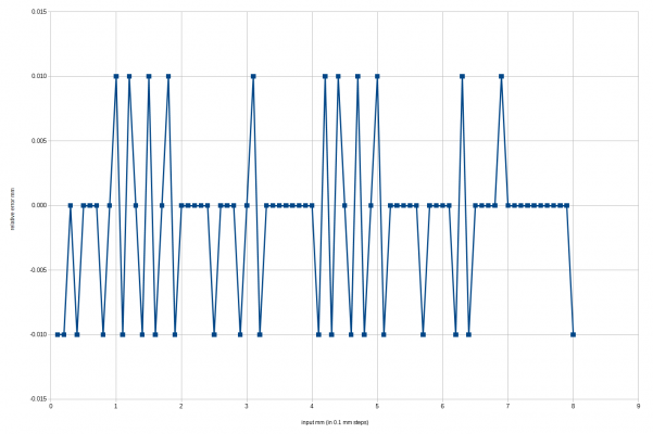
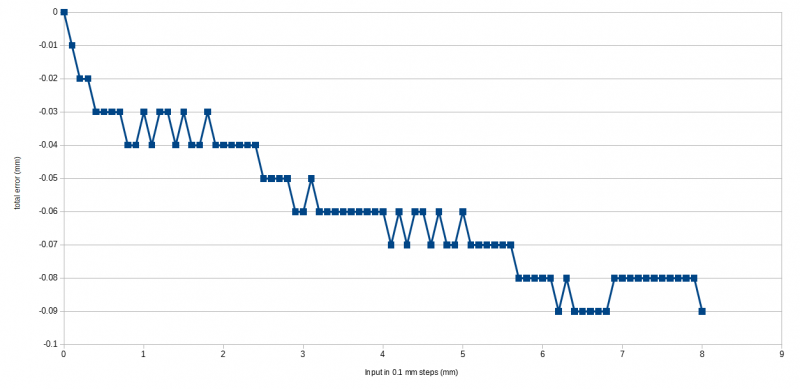
I put the Rino back into the printer, but instead of the original 36 tooth drive pulleys with HTD-3M belt, I used 40 tooth drive pulleys (I changed belt clamps and upper pulley plates to keep the belts parallel to the guide rails, too). That change took the Z axis resolution from 888.88888 usteps/mm (55.5555 full steps per mm) to 800 usteps/mm and 50 full steps per mm, much nicer numbers. I had never run the stepping tests on the Rino, so I decided to run the same tests, stepping the Z axis 8mm in 0.1 mm steps, as that should be two complete revs of the worm gear.
Results:
Anyone have any idea why the cumulative error would keep increasing? It's as if the gear ratio is not exactly 30:1...
Ultra MegaMax Dominator 3D printer: [drmrehorst.blogspot.com]
|
Re: Comparing worm gear drives- any ideas? April 16, 2018 11:00AM |
Registered: 11 years ago Posts: 335 |
You typically don't use a dial gauge to measure absolute distances because if the plunger is at an angle the measurement will be off. A more accurate way to measure a displacement is to zero the dial gauge on the bed, jog it down X, then insert an X gauge block and verify that the gauge still reads zero.
That being said, you've measured a fairly large error so its possible that the bed is moving to a location where it has more leverage on the frame, or that the belt has stretch varying with the length of loaded belt between the drive pulley and the bed. Maybe measure the compliance of the bed under say 500g load at two locations and see if one spot is less rigid than another?
I don't like measuring linear errors of this sort because if you don't have periodic error (or horrific mechanical problems) the screw/gear/pulley will be more accurate than your measuring tools. Technically you could change the steps/mm to compensate for some types of belt stretch, but then you have to ask yourself if you really want to extrapolate the measurement from a 1" dial gauge over the entire printer travel (especially since such errors will also vary with load).
I might play that game if I had a surface plate, level, and a set of gauge blocks, but its ridiculous to assume that calculating steps/mm over an 8" inch travel by measuring a 1" section with a 12$ dial gauge will be an improvement. Just do the math and use the theoretical number.
Also note that if you are measuring displacement at only one point the table could be rolling/pitching and it would look like a linear error (over short distances).
PS: Its a dense read, but Foundations of Mechanical Accuracy is available online and is quite interesting even in the context of 3d printing: [pearl-hifi.com]
Edited 3 time(s). Last edit at 04/16/2018 11:27AM by 691175002.
|
Re: Comparing worm gear drives- any ideas? April 16, 2018 06:56PM |
Registered: 11 years ago Posts: 5,780 |
I guess I hadn't thought it through sufficiently. It's entirely possible that the plunger in the gauge isn't exactly perpendicular to the bed plate (though it should be close).
The error isn't due to belt stretching. It would be going in the other direction if the belt were stretching, and this measurement was made with no load on the bed. I have measured belt stretch to be about 42 um per kg of load on the bed.
I don't think there's any issue with the bed tilting. I haven't seen any evidence of that sort of thing in prints.
Foundations of Mechanical Accuracy looks like a good read, and I'm having foot surgery in a couple days, so I'm going to have some time on my hands...
Ultra MegaMax Dominator 3D printer: [drmrehorst.blogspot.com]
Sorry, only registered users may post in this forum.
