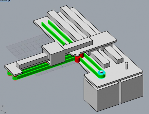
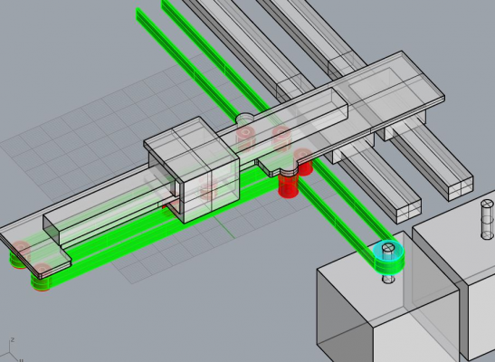
Cantilevered dual wire gantry
Posted by ruyvieira
|
Cantilevered dual wire gantry December 15, 2019 09:05PM |
Registered: 5 years ago Posts: 50 |
The motors are represented in 1:1 size, the arm itself is a lot shorter. Inspired by this ( [www.youtube.com] ), but trying to make it cartesian.
May have some advantages as far as accuracy goes since you can make it with just 1 linear rail per axis (the axis that supports the arm can be made with a double width MGN15, for example), may have a bit more ringing due to belt length and the fact that the arm is cantilevered. Shouldn't experience crosstalk between axes.
|
Re: Cantilevered dual wire gantry December 19, 2019 12:12AM |
Registered: 8 years ago Posts: 1,671 |
|
Re: Cantilevered dual wire gantry December 19, 2019 04:53AM |
Admin Registered: 11 years ago Posts: 3,096 |
Quote
MechaBits
belt path for the other motor?
Exactly what I was wondering about!
http://www.marinusdebeer.nl/
|
Re: Cantilevered dual wire gantry December 19, 2019 08:39AM |
Registered: 6 years ago Posts: 1,007 |
I guess the other belt is simply: just an idler opposite the motor, the belt being attached to the gantry and move it in Y.
The point is that this cantilever approach offers no benefit here, just potential trouble.
As for "accuracy" ? Compared to what ?
Edited 1 time(s). Last edit at 12/19/2019 08:42AM by MKSA.
"A comical prototype doesn't mean a dumb idea is possible" (Thunderf00t)
The point is that this cantilever approach offers no benefit here, just potential trouble.
As for "accuracy" ? Compared to what ?
Edited 1 time(s). Last edit at 12/19/2019 08:42AM by MKSA.
"A comical prototype doesn't mean a dumb idea is possible" (Thunderf00t)
|
Re: Cantilevered dual wire gantry December 19, 2019 08:42AM |
Registered: 11 years ago Posts: 5,780 |
Um, I think the other motor moves the gantry back and forth.
What is "wire"?
Why wouldn't you put the belts between the two (Y axis?) guide rails instead of off to one side? I think the mechanism would move smoother and be less likely to bind that way, and spacing the guide rails a little further apart would make the far end of the X axis more stable.
Ultra MegaMax Dominator 3D printer: [drmrehorst.blogspot.com]
|
Re: Cantilevered dual wire gantry December 20, 2019 05:12PM |
Registered: 5 years ago Posts: 50 |
Quote
MechaBits
belt path for the other motor?
This:
Quote
MKSA
I guess the other belt is simply: just an idler opposite the motor, the belt being attached to the gantry and move it in Y.
The point is that this cantilever approach offers no benefit here, just potential trouble.
What kind of trouble?
Quote
As for "accuracy" ? Compared to what ?
To a corexy or a delta. If you build it square, it will stay square forever. No need to match belt tension, make it just a little bit tight and that's it. Resolution calibration is simpler too, just measure how much each axis moves and adjust your steps/mm, no need for trickery to get around the fact that each motor does one diagonal, or god knows what if you have a Delta. If you use just a single rail for the y axis (a MGW15, for example), you won't need to bother with trying to align 2 parallel rails. Yes I know many people think this is a simple task, but since people aren't using precision ground flat surfaces or correctly specified linear rails this isn't the case.
Quote
the_digital_dentist
Um, I think the other motor moves the gantry back and forth.
What is "wire"?
I think the dude that coined the term "dual wire gantry" came up with it after dismantling an old pen plotter which used steel wire instead of a belt. I don't know what this should be called.
Quote
Why wouldn't you put the belts between the two (Y axis?) guide rails instead of off to one side? I think the mechanism would move smoother and be less likely to bind that way, and spacing the guide rails a little further apart would make the far end of the X axis more stable.
You're 100% right, but I think that by using a wider linear rail, I can get away with using just one.
EDIT: depending on the arm length, using the standard-width linear rail works fine too, but the "X-axis" rail needs to be a little longer so that I can bolt it down on the other side in order for it to function as a structural element, kinda like this
Since I haven't seen this belt path being used anywhere else, I name it Cross-bot
Edited 1 time(s). Last edit at 12/20/2019 06:01PM by ruyvieira.
|
Re: Cantilevered dual wire gantry December 25, 2019 08:34PM |
Registered: 7 years ago Posts: 507 |
You can simplify and shorten the belt path for the X axis if you go for a moving X rail design like this:
[ae01.alicdn.com]
You'd shorten it by a factor of twice the length of your x axis. Just fix both ends of the belt to one end of the Y axis, the motor to the other end and run the belt following the perimeter of the X and Y rails. You maintain the 2:1 gearing from the block and tackle, and the X axis movement is independent from the Y axis movement. Note, since you have a cantilevered design with just one Y rail, you can actually add a block and tackle mechanism for driving the Y axis as well, that way your steps/mm are the same for both axis.
Out of curiosity, why make it cantilevered in the first place if you're worried about accuracy and stuff? They're known for having rigidity issues that cause vibration at higher speeds, and drooping from their own weight.
|
Re: Cantilevered dual wire gantry March 02, 2020 10:09AM |
Registered: 7 years ago Posts: 36 |
|
Re: Cantilevered dual wire gantry March 02, 2020 12:35PM |
Registered: 8 years ago Posts: 1,671 |
|
Re: Cantilevered dual wire gantry December 15, 2020 02:50AM |
Registered: 11 years ago Posts: 364 |
i have been playing around with a core t as it is called . i made a mistake of moving the entore gantry up for the z axis which i have recently changed. overall it is better to use linear rails
[www.instagram.com]video
[www.instagram.com]video
|
Re: Cantilevered dual wire gantry December 17, 2020 05:28AM |
Admin Registered: 11 years ago Posts: 3,096 |
Quote
ekaggrat
i have been playing around with a core t as it is called . i made a mistake of moving the entore gantry up for the z axis which i have recently changed. overall it is better to use linear rails
[www.instagram.com]video
Linear rails, definitely. The wheels of the V-slot roller will wear faster and unevenly in this cantilever design. The wheels on the hotend side will wear faster on the bottom edge, and the wheels on the controller side will wear faster on the top edge.
Are you using A4988 drivers with a SKR 1.3??? I would suggest getting TMC2208 or TMC2209, the latter running much cooler when used with low amperage (I see you're using a closed case).
http://www.marinusdebeer.nl/
Sorry, only registered users may post in this forum.


