Large machine with light X-carriage - Which motion system?
Posted by Ohmarinus
|
Large machine with light X-carriage - Which motion system? September 15, 2020 04:48AM |
Admin Registered: 11 years ago Posts: 3,096 |
The machine I'm now going to build will be able to draw A0 format, my previous machine has a build format of 450x550mm and uses CoreXY, but it's reaching a limitation and that is that the belt paths are becoming excessively long.
I've been looking for examples but can only find large CNC machines using Nema23 motors and everything beefy. I want this machine to be lightweight and the X-carriage is so lightweight that Nema17 should be fine. The entire X-axis including the linear rods and carriage weigh around the same as a somewhat heavier heated bed setup.
The dimensions of the build plate are around 841x1189mm.
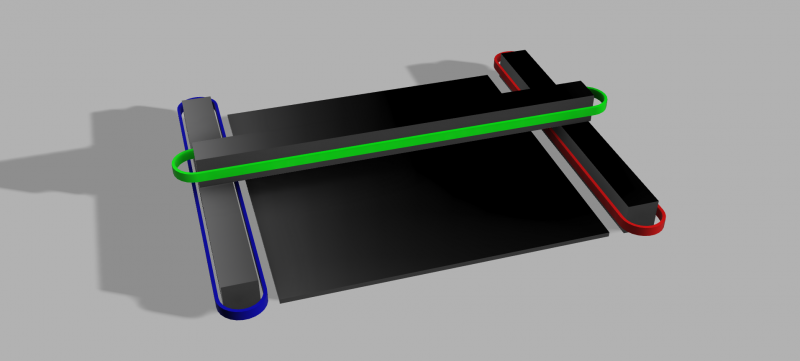
Now I was thinking maybe it would be easiest to give each axis their own motor, X-axis gets one motor that rides on the axis itself, the Y-axis gets two motors, one to drive each separate belt and the Z-axis is not used to raise anything heavy, only a small tool. Maybe I have to connect the Y-axis motors with a rod to make sure the motors don't go out of sync. I was thinking to use a TMC2209 driver for the Y-axis since it has good amperage.
In the image you see a very simple depiction of what I have in mind (I don't know the name of this system), but I'm wondering if there are other interesting solutions. I'm not going to use Hbot that's for sure as I don't want any headaches.
If anyone has suggestions for terms to google, or knows of some sturdy yet simple motion systems, I'm all ears. I prefer to use belts and 3D-printed parts to mount everything.
http://www.marinusdebeer.nl/
|
Re: Large machine with light X-carriage - Which motion system? September 15, 2020 06:18AM |
Admin Registered: 16 years ago Posts: 13,886 |
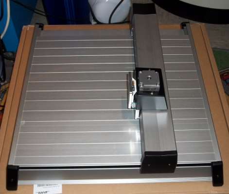
... pretty the same, as in your design, but 90deg turned belts is the "stone-old" buildup, used for flatbed-plotters and such 
Have one in A3, which has NEMA17 steppers one for every axis (long rod with two pulleys for the two Y-belts).
Viktor
--------
Aufruf zum Projekt "Müll-freie Meere" - [reprap.org] -- Deutsche Facebook-Gruppe - [www.facebook.com]
Call for the project "garbage-free seas" - [reprap.org]

Have one in A3, which has NEMA17 steppers one for every axis (long rod with two pulleys for the two Y-belts).
Viktor
--------
Aufruf zum Projekt "Müll-freie Meere" - [reprap.org] -- Deutsche Facebook-Gruppe - [www.facebook.com]
Call for the project "garbage-free seas" - [reprap.org]
|
Re: Large machine with light X-carriage - Which motion system? September 16, 2020 11:17AM |
Admin Registered: 11 years ago Posts: 3,096 |
Quote
VDX
... pretty the same, as in your design, but 90deg turned belts is the "stone-old" buildup, used for flatbed-plotters and such
Have one in A3, which has NEMA17 steppers one for every axis (long rod with two pulleys for the two Y-belts).
[attachment 116708 XY-Plotter1.png] [attachment 116709 XY-Plotter2.png]
Oh look at that, that actually looks very inspiring, and similar to the Roland machine I have sitting here, being all dormant in a corner because I can't find a suitable power supply and I can't find a replacement wheel for it.
That actually looks like a very nice and clean design. I think I could definitely build something similar. It looks like the Y-motor is a through-hole motor. Maybe I can remove the center rod from one of my stepper motors and replace it with something longer.. Hmm.. I'll have a look at it. Thanks!
http://www.marinusdebeer.nl/
|
Re: Large machine with light X-carriage - Which motion system? September 16, 2020 12:32PM |
Admin Registered: 16 years ago Posts: 13,886 |
... could be easier (and more torque too), if you set the stepper beside the double-axis and use a small->big pulley-pair (small pulley on the stepper, bigger on the axis) connected with a short belt-loop 
Viktor
--------
Aufruf zum Projekt "Müll-freie Meere" - [reprap.org] -- Deutsche Facebook-Gruppe - [www.facebook.com]
Call for the project "garbage-free seas" - [reprap.org]

Viktor
--------
Aufruf zum Projekt "Müll-freie Meere" - [reprap.org] -- Deutsche Facebook-Gruppe - [www.facebook.com]
Call for the project "garbage-free seas" - [reprap.org]
|
Re: Large machine with light X-carriage - Which motion system? September 16, 2020 02:53PM |
Registered: 11 years ago Posts: 5,780 |
I made a corexy mechanism that's 1.8m x 0.8 m using stacked 6 mm wide belts. It works well in the sand table. I had to make wide flanged pulleys using stacked ball bearings and printed flanges/tires to keep the belts on the pulleys. It originally used stepper motors but I kept running into the performance limits of the motors so I installed servomotors and now it's much better.
In the video you can see a wood cross brace at about the middle of the Y axis rails. That was needed because the belt tension was causing the Y axis rails (45 mm t-slot) to bow outward.
Ultra MegaMax Dominator 3D printer: [drmrehorst.blogspot.com]
In the video you can see a wood cross brace at about the middle of the Y axis rails. That was needed because the belt tension was causing the Y axis rails (45 mm t-slot) to bow outward.
Ultra MegaMax Dominator 3D printer: [drmrehorst.blogspot.com]
|
Re: Large machine with light X-carriage - Which motion system? September 26, 2020 09:43AM |
Admin Registered: 11 years ago Posts: 3,096 |
Quote
the_digital_dentist
I made a corexy mechanism that's 1.8m x 0.8 m using stacked 6 mm wide belts. It works well in the sand table. I had to make wide flanged pulleys using stacked ball bearings and printed flanges/tires to keep the belts on the pulleys. It originally used stepper motors but I kept running into the performance limits of the motors so I installed servomotors and now it's much better.
In the video you can see a wood cross brace at about the middle of the Y axis rails. That was needed because the belt tension was causing the Y axis rails (45 mm t-slot) to bow outward.
Thank looks very good as well. For this first concept I have a very small budget, so reusing stepper motors and electronics that I have in my possession is key. What kind of linear guides do you use on the long side?? I can't make it out!
http://www.marinusdebeer.nl/
|
Re: Large machine with light X-carriage - Which motion system? September 26, 2020 08:42PM |
Registered: 11 years ago Posts: 5,780 |
The slots in the rails are the guides, and I used UHMW, and later PTFE blocks that fit in the slots for the bearings. You can see more here.
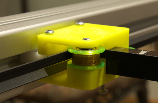
This is one of the Y axis bearing blocks- you can just see the white block of PTFE that fits into the slot in the frame rail, hiding behind the belts on the left.
The latest version of the bearing block design has one of the PTFE bearings spring loaded to prevent the whole X axis from shifting when the magnet carriage reverses direction in X. It increases friction a bit, but the servomotors don't mind. The whole thing runs a lot quieter when the X axis doesn't shift.
The belts may look a little off- that's because I put twists in the belts to ensure that the smooth backs of the belts would contact the pulleys instead of the teeth. I found the teeth were making a lot of zipping noises when the mechanism ran any faster than about 200 mm/sec. The twists are in the long belt runs between the drive pulleys on the motors and the corner pulley blocks. That long, straight belt run (almost 2 m) requires some minimum tension to ensure that the belt doesn't sag enough to contact the Y axis bearing block.
The magnet carriage slides on PTFE bearings that contact the black, square aluminum tube that serves as the X axis guide rail. By using square tubing there's no need for a second rail because the carriage can't rotate on the square tube.
This whole method of construction is a bit sloppy but it is more than adequate for a sand table that draws in a very forgiving medium. I don't think it would work well for a 3D printer unless you are very particular about print quality.
Edited 1 time(s). Last edit at 09/26/2020 08:43PM by the_digital_dentist.
Ultra MegaMax Dominator 3D printer: [drmrehorst.blogspot.com]
|
Re: Large machine with light X-carriage - Which motion system? October 04, 2020 05:42AM |
Admin Registered: 11 years ago Posts: 3,096 |
Quote
the_digital_dentist
The slots in the rails are the guides, and I used UHMW, and later PTFE blocks that fit in the slots for the bearings. You can see more here.
This is one of the Y axis bearing blocks- you can just see the white block of PTFE that fits into the slot in the frame rail, hiding behind the belts on the left.
The latest version of the bearing block design has one of the PTFE bearings spring loaded to prevent the whole X axis from shifting when the magnet carriage reverses direction in X. It increases friction a bit, but the servomotors don't mind. The whole thing runs a lot quieter when the X axis doesn't shift.
The belts may look a little off- that's because I put twists in the belts to ensure that the smooth backs of the belts would contact the pulleys instead of the teeth. I found the teeth were making a lot of zipping noises when the mechanism ran any faster than about 200 mm/sec. The twists are in the long belt runs between the drive pulleys on the motors and the corner pulley blocks. That long, straight belt run (almost 2 m) requires some minimum tension to ensure that the belt doesn't sag enough to contact the Y axis bearing block.
The magnet carriage slides on PTFE bearings that contact the black, square aluminum tube that serves as the X axis guide rail. By using square tubing there's no need for a second rail because the carriage can't rotate on the square tube.
This whole method of construction is a bit sloppy but it is more than adequate for a sand table that draws in a very forgiving medium. I don't think it would work well for a 3D printer unless you are very particular about print quality.
Very nice solution, I already thought you were using the extrusions themselves as a guide. Indeed, with sand it's quite a forgiving medium, the only issue I can think of would be variable belt tension if your extrusions are not perfectly straight.
I have decided to probably get a bamboo plate which is light as well as flat. But first I'll make a tryout model with MDF. We have a huge CNC mill at work with which I can mill full plates (2440x1220mm) and this will be used to make the first prototype.
Thanks for the input so far, I think I have enough to work with for the coming weeks.
http://www.marinusdebeer.nl/
|
Re: Large machine with light X-carriage - Which motion system? October 04, 2020 09:52AM |
Registered: 11 years ago Posts: 5,780 |
The really long belts are pretty stretchy, so even though the layout doesn't keep the belts perfectly parallel to the guide rails, it works fine anyway. I'm running a sand table, not a pen plotter- you may need to work out a more solid way of ensuring that the belts are parallel to the rails if you want high precision and accuracy.
Ultra MegaMax Dominator 3D printer: [drmrehorst.blogspot.com]
Ultra MegaMax Dominator 3D printer: [drmrehorst.blogspot.com]
Sorry, only registered users may post in this forum.


