Building a CoreXY : machined or printed parts ?
Posted by yet-another-average-joe
|
Building a CoreXY : machined or printed parts ? December 03, 2022 01:14PM |
Registered: 4 years ago Posts: 90 |
I will build a Voron 2.4, the large one (350x350). Because it has a fixed bed and I do want a fixed bed. And I need something that prints fast.
The author warns against using CNC machined parts (vs ABS printed ones). Good news : I have conventional machine tools (used, industrial), no CNCs.
I've been searching why.
I found some answers, but none makes sense to me.
1 - machining from STLs does not work because tolerancing and shrinking are taken into account at design time. BS. Parts just have to be redesigned and retoleranced, no big deal : F360 files are open sourced.
2 - the gantry has to be flexible because it self adjusts, and auto trams and un-skews. Sounds even more BS : a machine tool, if it is rigid enough, is first leveled, then trammed, it does not have to be readjusted each and every time it is powered on.
3 - high frequency resonance is difficult to dampen (as far as I know, it is the opposite)
4 - I stopped googling...
My lathe and my milling machine were leveled then trammed. They can move a bit, because of the concrete (200mm, reinforced). But a 3D printer is not 1 or 2 tons !!!
So what ?
I can understand the weight argument for moving parts. It is a killer argument. But the other parts ?
Not being a professional, I will not pretend I always get +-0.01mm. More within +-0.02 to 0.03.
What would you recommand ? Machining everything, or just the static parts, or printing everything as it was designed for ? (CADing is not a problem)
|
Re: Building a CoreXY : machined or printed parts ? December 03, 2022 07:22PM |
Registered: 4 years ago Posts: 285 |
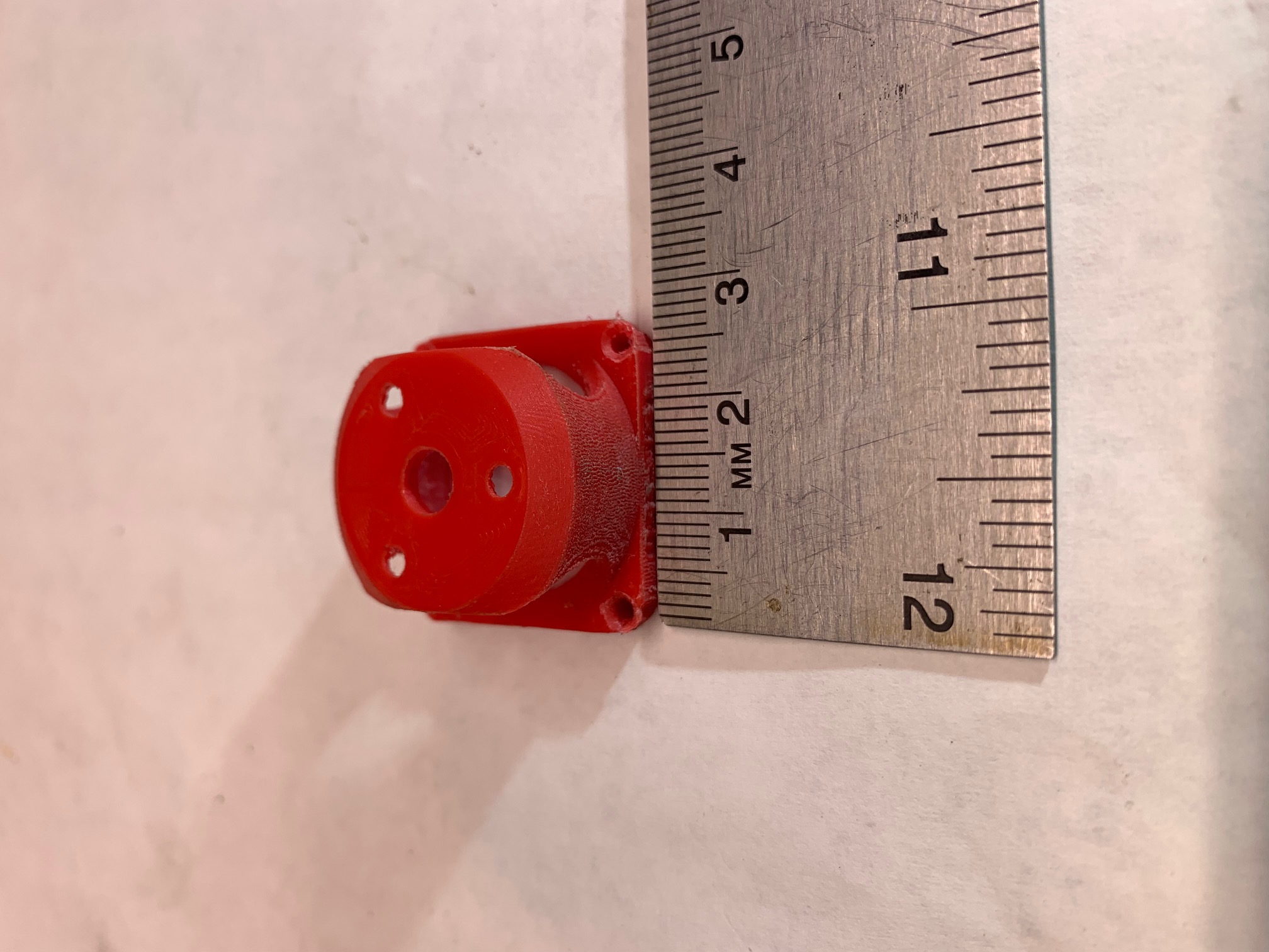
Machine everything that you can. Rigidity and repeatability is everything. Expecting high precision from plastic structural parts is ludicrous. I often print at 5 micron layer thickness, and at that point even temperature variations in the room have a strong affect on the outcome, as the printer components expand and contract by similar amounts.
Before a 5 micron print, I let the printer thermally stabilize for at least two hours, and make sure the room temperature is constant within 0.5 degree F. The worst instability on my delta is the carbon fiber rods for the mag ball arms, and even those were selected for expansion coefficient, one of the few "plastics" that allows you to do so.
But I'm after extreme precision, not speed, and am willing to let a very small, very precise, print take an entire day.
The attached 5 micron layer PLA part took over 17.5 hours to print.
|
Re: Building a CoreXY : machined or printed parts ? December 04, 2022 10:50AM |
Registered: 4 years ago Posts: 90 |
Thanks for your answer.
Will have to redesign many parts if not all, as most are not machinable with conventional machine tools. Also want the controller in a separate enclosure not under the bed.
Will be a different machine (except the head and the kinematics). I suspect a one year long project (at least). At first I wanted to build my own 3D printer, but got a Tornado for cheap ; had to retrofit a small chinese lathe ; I needed printed parts for covers and enclosures ; was thinking printing will be easy. 4.5 years later, still learning, and the parts are still on the shelves... Motors, controllers, OpenCNC-able PC motherboard, ballscrews, contactors, VFD, etc. and the small lathe is still in pieces !
What nozzle did you use ? (never tested under 0.3mm)
|
Re: Building a CoreXY : machined or printed parts ? December 04, 2022 11:15AM |
Registered: 4 years ago Posts: 285 |
|
Re: Building a CoreXY : machined or printed parts ? December 05, 2022 10:07AM |
Registered: 11 years ago Posts: 5,780 |
Yikes! That's one I haven't heard before!
Yes, your common sense is correct- machined metal parts are superior to the same parts printed from plastic.
Ultra MegaMax Dominator 3D printer: [drmrehorst.blogspot.com]
Yes, your common sense is correct- machined metal parts are superior to the same parts printed from plastic.
Ultra MegaMax Dominator 3D printer: [drmrehorst.blogspot.com]
|
Re: Building a CoreXY : machined or printed parts ? December 05, 2022 01:37PM |
Registered: 4 years ago Posts: 90 |
Heated chamber completed/tested (55°C only because of the bimetallic thermostat _ could be replaced with Marlin regulation). Currently redesigning the old Tornado for (conventional) machined parts. Hope I will be in the metal workshop within a couple of days.
About weight/mass, there's one detail I don't understand : Z-hop. Everytime I tried to use it, it was a fail (PET only : strings and blobs festival). This is the reason why I don't bother about wheight (vertical axis). But maybe am I wrong ?
Also, we rarely see ball screws for the Z axis. Is costs the only reason ?
|
Re: Building a CoreXY : machined or printed parts ? December 05, 2022 02:13PM |
Registered: 11 years ago Posts: 5,780 |
Z hop isn't very useful with stringy materials like PETG. It's great with ABS and PLA. IRIC, I shut it off for PETG and TPU.
Ball screws tend to cost more than lead screws, and the pitch tends to be much larger, so you give up some Z axis resolution unless you use pulleys to reduce the Z axis drive with them.
Ultra MegaMax Dominator 3D printer: [drmrehorst.blogspot.com]
Ball screws tend to cost more than lead screws, and the pitch tends to be much larger, so you give up some Z axis resolution unless you use pulleys to reduce the Z axis drive with them.
Ultra MegaMax Dominator 3D printer: [drmrehorst.blogspot.com]
|
Re: Building a CoreXY : machined or printed parts ? December 06, 2022 01:08PM |
Registered: 4 years ago Posts: 90 |
Z-hop : OK, I see.
Ballscrews : forgot this one... And then, attempting to regain resolution with pulleys, we lose precision because of runouts...
Or motor rather than pulley ?
200 steps/2mm vs 400 steps/5mm is not a huge difference : 0.01 vs 0.0125.
Talking about ballscrews, I just did a search and discovered that 12mm ballscrews with 4mm pitch are now available. I was unable to source 12mm 5 years ago in Europe. Smallest I found and purchased was 16mm/5mm. (game changer for the small CNC lathe project :16mm super hard to position for the cross slide, 12 just fine).
12mm ballscrew with 4mm pitch + 400 steps is equal to 8mm leadscrew 2mm pitch with 200 steps...
3x 12mm is probably rigid enough for holding a core X-Y mechanism. But having no play, they would require a super accurate positioning/parallelism. Moreover, if thermals considerations are to be taken into account (for example compromising parallelism), it's not something the average hobbist can tinker with. I didn't do any search about 3D printers and ballscrews fo now, Was just thinking. Still redesigning the old bed slinger ; why do all projects, even the simplest, always take much more time than expected - still not making chips, brains are boiling and burning the midnight oil
|
Re: Building a CoreXY : machined or printed parts ? December 06, 2022 01:26PM |
Registered: 7 years ago Posts: 363 |
If you're considering ball screws for Z, I'm not sure the juice is worth the squeeze. I've printed at 0.025mm z resolution (complete overkill btw) using inexpensive lead screws with plain brass nuts. Since Z movement is generally quite slow with low accelerations, gravity maintains positive engagement provided that the lead screws were well machined. Just for peace of mind I've since switched to machined delrin 'anti backlash' nuts but there was no perceivable improvement in maintainability, consistency or accuracy as a result. I would imagine that the same could be said about the *effective* differences between a lead screw and ball screw.
Remember, an FDM 3d printer is little more than a fancy hot glue gun.
Edited 1 time(s). Last edit at 12/06/2022 01:27PM by obelisk79.
Remember, an FDM 3d printer is little more than a fancy hot glue gun.
Edited 1 time(s). Last edit at 12/06/2022 01:27PM by obelisk79.
|
Re: Building a CoreXY : machined or printed parts ? December 06, 2022 02:14PM |
Registered: 11 years ago Posts: 5,780 |
I like belts for the Z axis. Probably about the same cost as lead screws by the time you add in either a brake or worm gear drive for the motor. Belts can't cause any wobbly artifacts in the prints, and you can use arbitrary lengths, as long as you like, which is nice for large/tall printers.
Ultra MegaMax Dominator 3D printer: [drmrehorst.blogspot.com]
Ultra MegaMax Dominator 3D printer: [drmrehorst.blogspot.com]
|
Re: Building a CoreXY : machined or printed parts ? December 07, 2022 01:51PM |
Registered: 4 years ago Posts: 90 |
Good points !
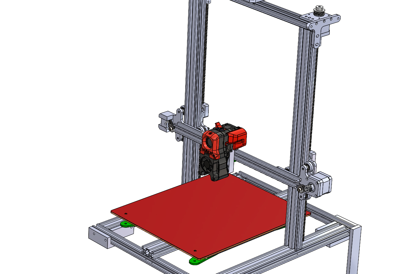
I'm rebuilding my bed slinger using such nuts. They are tight fit and nearly friction free : seems the anti backlash grubscrew is useless. If you look at the rendering I posted, you will see a pair behind the vertical 20x40..
BTW, do you think that a (re)build based on Creality CR10 / Tevo Tornado extrusions and machined parts could be interesting on the forum ? Too lazy to update my website (wrote nothing for the last 10 years). OTOH such mods are very common... Could be turning the machines on saturday or sunday. Because of 3D printing, nearly stopped machining ! Most makes not needing metal, and 3D being much cheaper (not taking into account the needle chips in the bed at night and the wife's rants about them)
Just a matter of shooting some pics, but very time consuming...
Thanks for your attention.
|
Re: Building a CoreXY : machined or printed parts ? December 07, 2022 04:22PM |
Registered: 11 years ago Posts: 5,780 |
Regarding Z axis resolution, you want full step resolution to be a "nice" number that is probably smaller that any layer thickness you'll ever print. For example, in my printer's Z axis I selected the pulleys to work with the motor's 200 steps/rev and the 30:1 reduction to yield 20 um per full step. When you print you want to print in multiples of the full step resolution to minimize Z axis artifacts in prints. A nice number like 20 um means I can print at 100, 200, 500 um, etc. because all are divisible by 20 um. If you use a motor with a planetary gear reducer you can end up with very odd value full step resolution (numbers like 17.581 um/full step) that will force you to use odd-ball values for the layer thickness because most (all?) planetary gear reducers have non integer reduction ratios (that you will find in the fine print of the specs). In the end it's all just numbers, but some are easier to keep in your head than others.
Ultra MegaMax Dominator 3D printer: [drmrehorst.blogspot.com]
Ultra MegaMax Dominator 3D printer: [drmrehorst.blogspot.com]
|
Re: Building a CoreXY : machined or printed parts ? December 09, 2022 07:17PM |
Registered: 4 years ago Posts: 90 |
Yes indeed ; 2.5 or 5 mm pitch would make life easier with direst drive, having 0.1mm resolution would be great... Hope the Voron offers this resolution (didn't have look for now, next year project...).
For now, started with the Tornado rebuild. Cut some stock, inventored billets and sorted scrap aluminium. Had to re-CAD some parts depending on what is available in the basement, and requires the less metal removal.
Started with the stupid Y axis. 6 rollers. From factory, on one side, all 3 are adjustable (eccentric nuts). On the other side, all three are fixed.
All rollers and bearings were shot (see picture), grinding as hell, and were later replaced. The old rollers were in such a shape they couldn't be adjusted.
From factory : rollers #1, #2 and #3 fixed ; #4, #5 and #6 are adjustable (eccentric nuts) ; Since when 3 points could be aligned somewhere in the universe ??? As a result one roller was allways spinning free.
Long ago, I added an eccentric at #2 while I was replacing the rollers for the first time.
Today I made a 3.5mm thick backplate (#7), adding rigidity to the assembly, and cancelling or at least reducing wobble. And discovered the terrible precision of the holes positions (stamped) ! Finally got it to work properly, smooth as butter, all rollers gently touching the V grooves. Of course this requires double eccentrics for rollers #2, #4, #5 and #6. Replaced with flanged eccentrics of course, OpenBuilds knockoffs. Will soon make a tool combining two wrenches so double eccentrics will easily be adjustable in perfect sync.
Tomorrow, the motor mount + tensioner. Rigid, machined, unlike the factory flexible crap made of stamped 3mm alu sheet. Redesigned with a proper belt alignment (parallel, unlike the original design)
For now, started with the Tornado rebuild. Cut some stock, inventored billets and sorted scrap aluminium. Had to re-CAD some parts depending on what is available in the basement, and requires the less metal removal.
Started with the stupid Y axis. 6 rollers. From factory, on one side, all 3 are adjustable (eccentric nuts). On the other side, all three are fixed.
All rollers and bearings were shot (see picture), grinding as hell, and were later replaced. The old rollers were in such a shape they couldn't be adjusted.
From factory : rollers #1, #2 and #3 fixed ; #4, #5 and #6 are adjustable (eccentric nuts) ; Since when 3 points could be aligned somewhere in the universe ??? As a result one roller was allways spinning free.
Long ago, I added an eccentric at #2 while I was replacing the rollers for the first time.
Today I made a 3.5mm thick backplate (#7), adding rigidity to the assembly, and cancelling or at least reducing wobble. And discovered the terrible precision of the holes positions (stamped) ! Finally got it to work properly, smooth as butter, all rollers gently touching the V grooves. Of course this requires double eccentrics for rollers #2, #4, #5 and #6. Replaced with flanged eccentrics of course, OpenBuilds knockoffs. Will soon make a tool combining two wrenches so double eccentrics will easily be adjustable in perfect sync.

Tomorrow, the motor mount + tensioner. Rigid, machined, unlike the factory flexible crap made of stamped 3mm alu sheet. Redesigned with a proper belt alignment (parallel, unlike the original design)
|
Re: Building a CoreXY : machined or printed parts ? December 09, 2022 08:11PM |
Registered: 4 years ago Posts: 285 |
Quote
yet-another-average-joe
Yes indeed ; 2.5 or 5 mm pitch would make life easier with direst drive, having 0.1mm resolution would be great... Hope the Voron offers this resolution (didn't have look for now, next year project...).
For now, started with the Tornado rebuild. Cut some stock, inventored billets and sorted scrap aluminium. Had to re-CAD some parts depending on what is available in the basement, and requires the less metal removal.
Started with the stupid Y axis. 6 rollers. From factory, on one side, all 3 are adjustable (eccentric nuts). On the other side, all three are fixed.
All rollers and bearings were shot (see picture), grinding as hell, and were later replaced. The old rollers were in such a shape they couldn't be adjusted.
From factory : rollers #1, #2 and #3 fixed ; #4, #5 and #6 are adjustable (eccentric nuts) ; Since when 3 points could be aligned somewhere in the universe ??? As a result one roller was allways spinning free.
Long ago, I added an eccentric at #2 while I was replacing the rollers for the first time.
Today I made a 3.5mm thick backplate (#7), adding rigidity to the assembly, and cancelling or at least reducing wobble. And discovered the terrible precision of the holes positions (stamped) ! Finally got it to work properly, smooth as butter, all rollers gently touching the V grooves. Of course this requires double eccentrics for rollers #2, #4, #5 and #6. Replaced with flanged eccentrics of course, OpenBuilds knockoffs. Will soon make a tool combining two wrenches so double eccentrics will easily be adjustable in perfect sync.
[attachment 119937 20221209_225739-Copie.jpg]
Tomorrow, the motor mount + tensioner. Rigid, machined, unlike the factory flexible crap made of stamped 3mm alu sheet. Redesigned with a proper belt alignment (parallel, unlike the original design)
Kinematically, why do this? 3 points define a plane. If rollers 1 and 3 are fixed, and roller 5 is adjustable, that's all you need to constrain the carriage under all conditions. The other rollers are superfluous, and you probaly cannot get them to share the load equally anyway. I'd even be tempted to place the adjustable roller 5 under compression spring tension, so that only rollers 1 and 3 actually determine the tracking accuracy. Using standard V groove bearings, and ground rods would give you precision comparable to linear rails at a very low cost. You could even get precicion rods at low cost that would "lay" into the existing grooves in the aluminum extrusion, giving you a hard wear surface and eliminating the delrin rollers, a major source of wear and error.
Just a thought, but one I've seriously considered doing to my go-to delta. Which prints well at 5 micron layer heights.
Edited 1 time(s). Last edit at 12/09/2022 08:18PM by rq3.
|
Re: Building a CoreXY : machined or printed parts ? December 10, 2022 11:04AM |
Registered: 4 years ago Posts: 90 |
I am not building a printer, I am rebuilding a Tornado that came with the Y axis (bed) on six rollers. The bed is a thick and heavy borosilicate plate (total > 2.5 kg).
These ball bearings are not made for axial loads (625 are not deep groove bearings, come from China, and are crap : have 30 rollers, 50% are dead on arrival, not even lubricated, and with a terrible play !).
6 rollers is 33% decreasing this axial load ; Tornado, CR10 and these 300x300x400 printers all come with six rollers on open builds extrusions. The design is terrible, but it is designed this way.
I do all this at no cost, with parts I have for a long time (remember when everything was 1 USD on Ali...), materials in stock and my tooling and machine tools. I will not spend a cent on this printer, except replacing the consumables that need to (and I already have in stock). Immediate cost is zero, and will remain zero : will not purchase any part like ground rods.
This machine is crap, and not worth spending a cent trying to make a Prusa from it ! don't make a racehorse out of a donkey. Not even sure frame and gantry are square and flat (will see that later on the surface plate). Main hobbies are mechanics, machining, electronics and coding. It's for fun and for fun only, a pretext for cutting metal and making chips ! Once this rebuild is completed, it will be a Voron (with as many machined parts as possible). No kit. Sourcing everything, using branded parts when available.
The Tornado will print the needed ABS parts and that's it. Will most likely be retired or rarely used. But rebuilding it is fun. If it wasn't, no doubt I'd purchase a Prusa.
|
Re: Building a CoreXY : machined or printed parts ? December 15, 2022 06:41PM |
Registered: 4 years ago Posts: 90 |
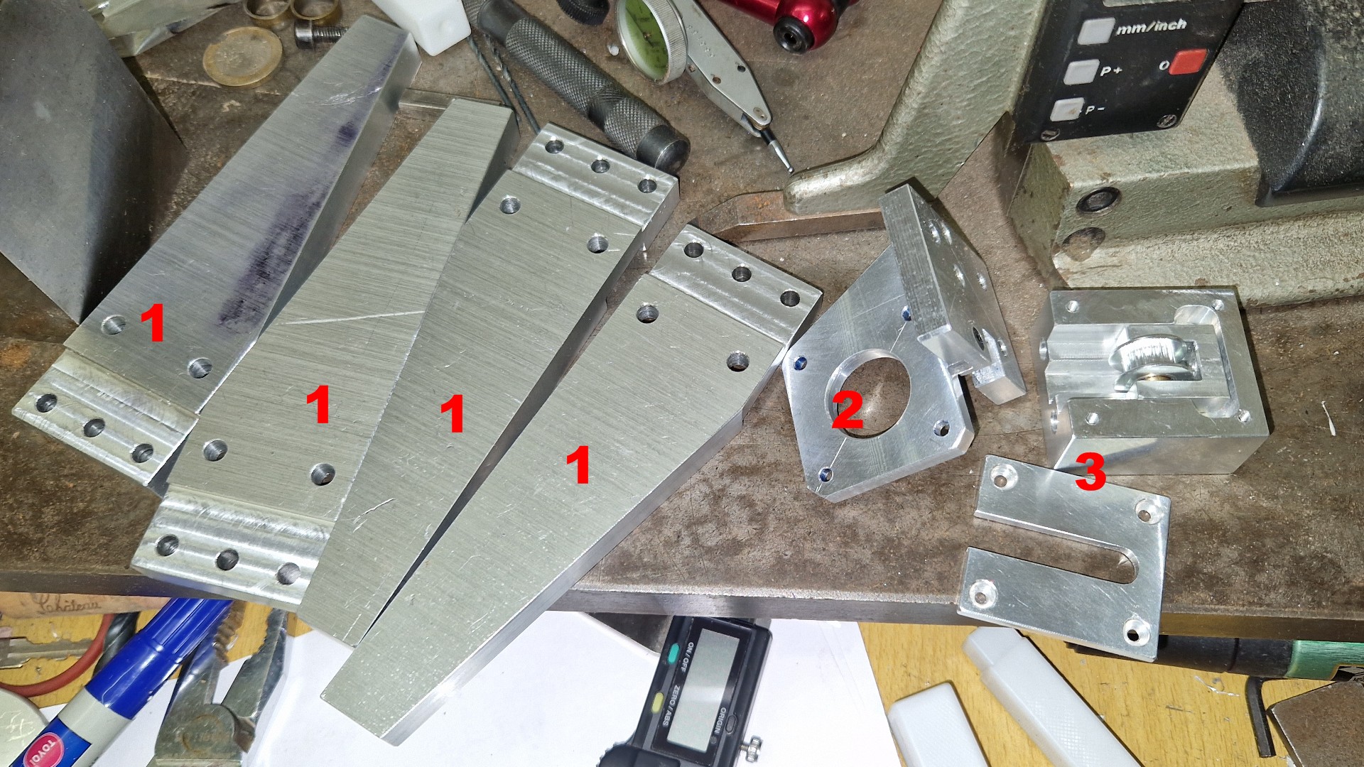
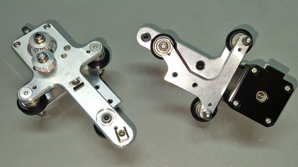
Some progress...
Made the raisers (1) so a repurposed food dehydrator can seat underneath. Y motor mount (2), and Y belt tensioner (3). Motor mount and belt tensioner are made so the belt is anywhere parallel to the bed carriage (unlike the incredibly crappy Creality/Tevo design.
Also designed and machined so the whole Y axis actuator can be removed form the printer as one sub assembly (extruded rail + motor mount + tensioner).
No fancy machining (like nice chamfers/fillets, just functionnal parts.
Work in progress...
|
Re: Building a CoreXY : machined or printed parts ? December 15, 2022 10:48PM |
Registered: 4 years ago Posts: 285 |
|
Re: Building a CoreXY : machined or printed parts ? December 15, 2022 11:47PM |
Registered: 11 years ago Posts: 5,780 |
Very nice. Your machining skills are far beyond my own- I take the easy way out and use rectangular tubing for motor and pulley mounts. That way I only have to mill the ends square (not really necessary, but nicer to look at) and drill holes accurately.
Ultra MegaMax Dominator 3D printer: [drmrehorst.blogspot.com]
Ultra MegaMax Dominator 3D printer: [drmrehorst.blogspot.com]
|
Re: Building a CoreXY : machined or printed parts ? December 16, 2022 01:09PM |
Registered: 4 years ago Posts: 90 |
Milling the ends of extrusions is something I would avoid at any price. There are two ways to do this (in my shop).
The simple one : the extrusion in the vice, and side milling ; I don't like that because the surface finish is not great, vibrations, tool flexing, and chip recycling... The smallest deviation will be amplified when another long part is bolted to.
The complicated one, that gives the best results, was demonstrated by Joe Pieckzinsky on his (amazing) YT channel. This extremely skilled toolmaker positioned the part vertically, attached to the table with a jig, and machined using the end of the tool. Needless to say he spent some time on tuning every detail ! He has an industrial CNC but did this operation on the Bridgeport. I didn't even consider attempting to do this !
The best are the presicion circular saw, or the horizontal milling machine (or a shaper for retro machining lovers). Best milling machines have horizontal + vertical spindles. Mine is vertical only.
This being said, making it was tedious. Not being skilled enough, there were many useless operations and tool changes. But for the first time, I got +-0.01mm everywhere. Not kidding. It's been 20+ years since I started building a metal workshop, 14 years I got the milling machine... Seemed easy, discovered it is not. And 3D printing is even more difficult.
Dreaming of a small CNC. Even a good, rigid, router would have done that fast and clean... With fancy chamfers and fillets !
Still a dozen parts to make before the printer is alive again. For machining, I was thinking days. Will be weeks...
[EDIT] added a few pictures.
Models are from the Creality/Tevo knockoff ; shows how the motor, tensioner and belt (not shown) are positioned. Why ??? First, why isn't the motor pulley pitch diameter level with the carriage ? Why this idler ? Why is this idler not toothed ? (should be, according to the Gates datasheets and guidelines, due to its diameter...). Moreover, it is a useless part, that does not make the belt parallel to the extrusion... The tensionner is not better. Should be toothed. (on the other hand, flanged bearings certainly turn more true than extruded pulleys...)
The new design shows 4 improvements.
- the motor pulley is mounted so it is as near to the motor front bearing as possible : less stress on the bearing (had one shot after 2 years) ; you may notice a (minor) problem on my design : I used a motor model with a 22mm shaft, as on the Tevo Tornado, but the replacement one has a 20mm shaft, and didn't notice. Luckily The grubscrew still seats on the flat !
- the motor pulley is positioned so theres's no need for an idler
- the belt is perfectly parallel to the direction of moves
- the tensioner pulley is toothed
(sorry for the focus and DOF, took the pics with the phone. Years I want to test focus stacking with the DSLR macro lens, and always out of time or lazy)
Edited 1 time(s). Last edit at 12/16/2022 05:02PM by yet-another-average-joe.
The simple one : the extrusion in the vice, and side milling ; I don't like that because the surface finish is not great, vibrations, tool flexing, and chip recycling... The smallest deviation will be amplified when another long part is bolted to.
The complicated one, that gives the best results, was demonstrated by Joe Pieckzinsky on his (amazing) YT channel. This extremely skilled toolmaker positioned the part vertically, attached to the table with a jig, and machined using the end of the tool. Needless to say he spent some time on tuning every detail ! He has an industrial CNC but did this operation on the Bridgeport. I didn't even consider attempting to do this !
The best are the presicion circular saw, or the horizontal milling machine (or a shaper for retro machining lovers). Best milling machines have horizontal + vertical spindles. Mine is vertical only.
This being said, making it was tedious. Not being skilled enough, there were many useless operations and tool changes. But for the first time, I got +-0.01mm everywhere. Not kidding. It's been 20+ years since I started building a metal workshop, 14 years I got the milling machine... Seemed easy, discovered it is not. And 3D printing is even more difficult.
Dreaming of a small CNC. Even a good, rigid, router would have done that fast and clean... With fancy chamfers and fillets !
Still a dozen parts to make before the printer is alive again. For machining, I was thinking days. Will be weeks...
[EDIT] added a few pictures.
Models are from the Creality/Tevo knockoff ; shows how the motor, tensioner and belt (not shown) are positioned. Why ??? First, why isn't the motor pulley pitch diameter level with the carriage ? Why this idler ? Why is this idler not toothed ? (should be, according to the Gates datasheets and guidelines, due to its diameter...). Moreover, it is a useless part, that does not make the belt parallel to the extrusion... The tensionner is not better. Should be toothed. (on the other hand, flanged bearings certainly turn more true than extruded pulleys...)
The new design shows 4 improvements.
- the motor pulley is mounted so it is as near to the motor front bearing as possible : less stress on the bearing (had one shot after 2 years) ; you may notice a (minor) problem on my design : I used a motor model with a 22mm shaft, as on the Tevo Tornado, but the replacement one has a 20mm shaft, and didn't notice. Luckily The grubscrew still seats on the flat !
- the motor pulley is positioned so theres's no need for an idler
- the belt is perfectly parallel to the direction of moves
- the tensioner pulley is toothed
(sorry for the focus and DOF, took the pics with the phone. Years I want to test focus stacking with the DSLR macro lens, and always out of time or lazy)


Edited 1 time(s). Last edit at 12/16/2022 05:02PM by yet-another-average-joe.
|
Re: Building a CoreXY : machined or printed parts ? December 16, 2022 06:03PM |
Registered: 11 years ago Posts: 5,780 |
One of the few milling operations I do is milling the ends of t-slot square so I can bolt it directly together. I used a 3 flute, 1/2" diameter tungsten carbide tool that has a 2" long cutting length so I can cut up to 50mm t-slot in a single pass. With a sharp tool taking only a little off at a time, I get almost mirror finish on the milled ends of the t-slot. The milled pieces bolt together square every time. IRIC I bought the tool via ebay for about $30 a few years ago. I use a Bridgeport mill at the makerspace most of the time, though once in a while I have to use a Gorton knee mill that I don't like much.
Edited 1 time(s). Last edit at 12/16/2022 06:05PM by the_digital_dentist.
Ultra MegaMax Dominator 3D printer: [drmrehorst.blogspot.com]
Edited 1 time(s). Last edit at 12/16/2022 06:05PM by the_digital_dentist.
Ultra MegaMax Dominator 3D printer: [drmrehorst.blogspot.com]
|
Re: Building a CoreXY : machined or printed parts ? December 17, 2022 05:47AM |
Registered: 3 years ago Posts: 92 |
Do you remember the name of the video? I'd like to see thatQuote
yet-another-average-joe
The complicated one, that gives the best results, was demonstrated by Joe Pieckzinsky on his (amazing) YT channel. This extremely skilled toolmaker positioned the part vertically, attached to the table with a jig, and machined using the end of the tool. Needless to say he spent some time on tuning every detail ! He has an industrial CNC but did this operation on the Bridgeport. I didn't even consider attempting to do this !

I just use aluminum foil shims to square up frames made out of T-slot.
|
Re: Building a CoreXY : machined or printed parts ? December 17, 2022 08:12PM |
Registered: 4 years ago Posts: 90 |
I was mistaken. He does not mill the end. It's about drilling / tapping. There's no choice there. Remembered the setup as a milling setup, probably because I hate side milling... This being said, today I had much better results side milling a different alu alloy (chips not as sticky as usual)
The video : [www.youtube.com]
Today, I made the plates for the Z motors. Two "dual shaft" motors on top of the printer ; lower one for the leadscrews, top one for the sync belt, and a tensioner with a crank (3D printed using ABS, will probably make it again from aluminium because it is fun). The extrusions are not 20x40 and 20x20 ; they are something like 20x40 and 20x20 but not 20x40 and 20x20, and nothing was square or parallel ! Had to do some machining in order to get reference surfaces for the motors and the leadscrews... Not 100% perfect because the ends of the Z extrusions are not perfectly square, and because of the cheap rigid couplers ; but far better (couldn't get the leadscrews parallel to the vertical extrusions). Have to make a pair of parts that will allow some shimming for a perfect parallelism. Will post pictures when it's done.
Are high quality extrusions dimensions accurate ? Are they perfectly parallel ? Could you recommand a brand ? Openbuilds is available in France. In Europe, we also have Ratrig (Portugal IIRC) : On their website, we can read : "manufactured in Europe to exact OpenBuilds spec" ; don't want to use the same crap my Tevo Tornado is made of !
I have another question...
Motors are now on top. This will minimize the effect of the couplers runout. I don't have reamers, so I can't machine nice couplers (but will get some for the coreXY project)... Anyway, leadsrcews are rolled, not machined + grounded. So threads concentricity is probably not the best.
I quickly tested the leadscrews against a metrology, hand scrapped cast iron surface plate. They are straight, not bent. I planed to let the lower ends unsupported. I never print tall models : there never will be a significant length floating in the air. Nuts are those popular Delrin rectangular ones with a grubscrew for backlash adjustments (but there's no play/backlash). Should I support the ends ? Of course, if supported, the ends have to be free to slide in the bearings, because steel and aluminium don't have the same expansion coefficients ! I read a lot about that, but still not sure about the conclusions (endless polemics...). Maybe overthinking, but expansion is far from negligible at 50-60°C...
[EDIT] differential expansion = 0.145mm for 350mm, from 20 to 55°C, aluminum vs steel, according to a online calculator. Could quickly kill motors bearings !
Edited 3 time(s). Last edit at 12/17/2022 08:22PM by yet-another-average-joe.
|
Re: Building a CoreXY : machined or printed parts ? December 23, 2022 09:21PM |
Registered: 4 years ago Posts: 90 |
Dual Z belt tensioner and motor plates completed.
Blue and yellow, PETG : the tensioner and plates I've been using for the last 4 years, inspired by Cornelly Cool designs (see Thingyverse) ; hugely improved the printing quality of this crappy printer. One of my very first designs...
[www.thingiverse.com]
The design was modified so it is easily machinable.
The black crank is the reason why I want to switch to a ABS capable printer. The print quality is so much better than PET or even PLA...
(the crank also will be machined, rq23 said "machine everything that you can". So be it...
Also machined two "bearings" for the lower end of the leadscrews. The leadscrews lenghts are calculated so these bearings can be easily removed without taking the whole printer apart. They are made of high density polyethylen (no Delrin by hand...). Of course, no threads, just a tight but slippery fit ; need a reference for alignments.
Edited 4 time(s). Last edit at 12/23/2022 10:06PM by yet-another-average-joe.
Blue and yellow, PETG : the tensioner and plates I've been using for the last 4 years, inspired by Cornelly Cool designs (see Thingyverse) ; hugely improved the printing quality of this crappy printer. One of my very first designs...
[www.thingiverse.com]
The design was modified so it is easily machinable.


The black crank is the reason why I want to switch to a ABS capable printer. The print quality is so much better than PET or even PLA...
(the crank also will be machined, rq23 said "machine everything that you can". So be it...

Also machined two "bearings" for the lower end of the leadscrews. The leadscrews lenghts are calculated so these bearings can be easily removed without taking the whole printer apart. They are made of high density polyethylen (no Delrin by hand...). Of course, no threads, just a tight but slippery fit ; need a reference for alignments.


Edited 4 time(s). Last edit at 12/23/2022 10:06PM by yet-another-average-joe.
|
Re: Building a CoreXY : machined or printed parts ? December 24, 2022 07:04PM |
Registered: 11 years ago Posts: 5,780 |
That seems like kind of an elaborate tensioner for an operation that will probably only be done one time...
Ultra MegaMax Dominator 3D printer: [drmrehorst.blogspot.com]
Ultra MegaMax Dominator 3D printer: [drmrehorst.blogspot.com]
|
Re: Building a CoreXY : machined or printed parts ? December 25, 2022 10:19AM |
Registered: 4 years ago Posts: 90 |
Not just a tensioner. It is mostly a Z crank wheel mechanism that can adjust belt tension. Called it tensioner, but it is misleading.
Could have been much simpler, with the Z crank wheel bolted to a pulley (left or right or both), plus a very simple tensioner (a idler + small arm). But everybody does it that way, and it isn't fun at all. If weight (mass) and inverted pendulum appear to be a problem despite reinforcement tubings (not on drawings), I will go this way. This thing is really heavy, even more when added to the two steppers ! Not sure I will keep this design, but it was fun to draw and machine.
And why make it simple when it can be complicated ?
Could have been much simpler, with the Z crank wheel bolted to a pulley (left or right or both), plus a very simple tensioner (a idler + small arm). But everybody does it that way, and it isn't fun at all. If weight (mass) and inverted pendulum appear to be a problem despite reinforcement tubings (not on drawings), I will go this way. This thing is really heavy, even more when added to the two steppers ! Not sure I will keep this design, but it was fun to draw and machine.

And why make it simple when it can be complicated ?
|
Re: Building a CoreXY : machined or printed parts ? December 25, 2022 04:59PM |
Registered: 11 years ago Posts: 5,780 |
|
Re: Building a CoreXY : machined or printed parts ? December 26, 2022 05:21PM |
Registered: 4 years ago Posts: 90 |
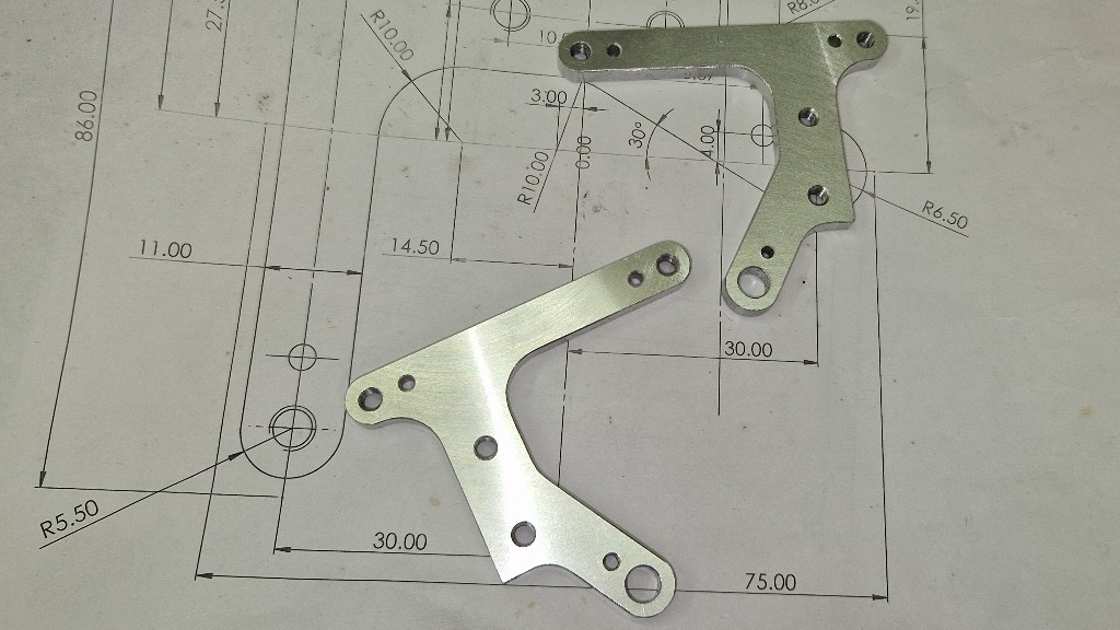
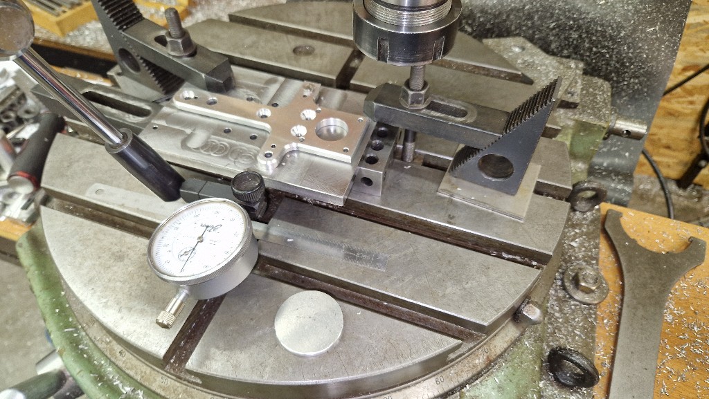
Today, started the Z carriage ; made the front plates, that still have to be contoured (will machine the jig tomorrow).
We can see :
- the sync belt tensioner/crank is not that big. Love it, and will keep it !
- reduced the Y tensioner. Smaller, with nice chamfers.
- the two plates (6mm thick) are accurate (+-0.015mm) ; with a salmon skin pattern : when tightening the vice, the metal slighltly bends. I think it is the reason for this slamon skin pattern (it' visual only, not measurable)
- proud for the cross pattern with the fly cutter : the head is properly trammed !


|
Re: Building a CoreXY : machined or printed parts ? January 04, 2023 05:43PM |
Registered: 4 years ago Posts: 90 |
No, it's not a dead project. It's a work in progress.
Struggling with centering, aligning, etc. because of stupid operations ordering decisions... Dreaming of a CNC... Some parts are completed, some others are to be finished, and a few still to be designed...
I discovered that all my couplers from Ali (motors to leadscrews) are a pile of crap, with an incredible runout. No choice : will have to make them... Even such basic parts are not properly machined ! (but are really easy to make)
Also suspect extruded pulleys are pure crap... Looking for any information about their geometry. I found information about belts profiles, but belts are infinite pulleys (= racks), and their geometry does not apply ; not being familiar with involute gear calculations, any information is welcome. As well as information about "poor man's profile projector", made of a DSLR + macro lens +- bellow and a dedicated open software (in order to make a fly cutter tool).
This is just the starting point for the old Tornado. Can't imagine the amount of work for a CoreXY, starting from scratch...
[EDIT] the coupler issue is more complex. The leadscrews are different outer diameters : 7.98 and 7.96mm and the couplers IDs are oversised on the 8mm side (not equiped with gage pins, so no measurements), and very hard to tighten ; nothing is matching. Best chance is turning the ends down to 5mm. It's hardened steel, unfortunately not just case hardened....
A good reason not to buy random leadscrews for the CoreXY project !!!
OTOH, for the Tornado, the motors being upside down, and not printing tall objects, the runout effects should be minimized. Probably not worth losing time on this problem.
Edited 1 time(s). Last edit at 01/05/2023 08:57AM by yet-another-average-joe.
|
Re: Building a CoreXY : machined or printed parts ? February 16, 2023 05:57PM |
Registered: 4 years ago Posts: 90 |
Follow up...
Having fun building a bed slinger from the old Tornado, the stock metal I ahve handy, and the metal workshop I've been building for the last 25 years.
Keeping the frame and the bed. The bed is on silicon "springs". Machined cups that will limit the XY plane springiness...
The Z carriages :
Made a NEMA17 form factor X tensionner ; moved the X home endstop to the right side, for easier cable management. Never understood why the controller always is on the left side. Being right handed, always been ennoyed with that...
The base : legs and corners ensure that it's a perfectly flat rectangle. Assembled on a machinist's hand scraped cast iron metrology surface plate. Machined parts have a tight fit, requiring a dead hammer for assmbly. Everything is flat and square.
Edited 2 time(s). Last edit at 02/16/2023 06:47PM by yet-another-average-joe.
Having fun building a bed slinger from the old Tornado, the stock metal I ahve handy, and the metal workshop I've been building for the last 25 years.
Keeping the frame and the bed. The bed is on silicon "springs". Machined cups that will limit the XY plane springiness...


The Z carriages :

Made a NEMA17 form factor X tensionner ; moved the X home endstop to the right side, for easier cable management. Never understood why the controller always is on the left side. Being right handed, always been ennoyed with that...


The base : legs and corners ensure that it's a perfectly flat rectangle. Assembled on a machinist's hand scraped cast iron metrology surface plate. Machined parts have a tight fit, requiring a dead hammer for assmbly. Everything is flat and square.


Edited 2 time(s). Last edit at 02/16/2023 06:47PM by yet-another-average-joe.
|
Re: Building a CoreXY : machined or printed parts ? February 16, 2023 06:10PM |
Registered: 4 years ago Posts: 90 |
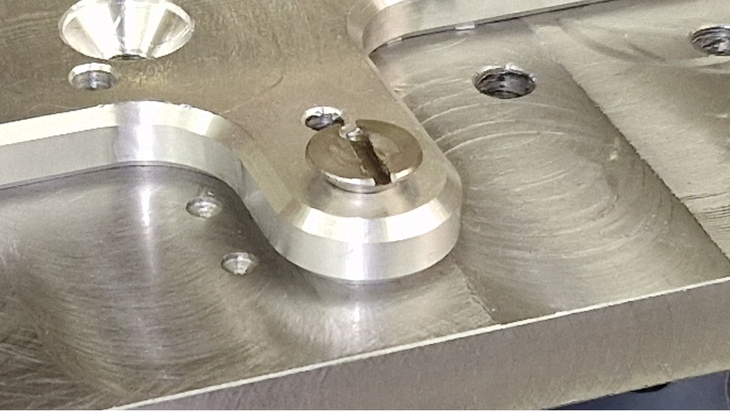
The corners for the XY base and the vertical extrusions ouldn't be assembled without multi threaded nuts. Such parts don't exist in the wild. Let's make them ! And nothing's more beutifull than blue chips made from steel by a carbide endmill !
Of course, nuts were zinc plated (or they quickly would tend to rust...)
(one of the triple thread nuts is messed up, most likely because of a chip in the vise, but luckilly still usable !)
I revised my mind about the Z axis. Work in progess. The first design was the worst idea I ever had ! Parts are now in the bin intended for casting.
New parts : there will be one motor and one motor only. Two motors was a lazy design. The new design everyone will undrstand watcing this picture :

Of course, nuts were zinc plated (or they quickly would tend to rust...)


(one of the triple thread nuts is messed up, most likely because of a chip in the vise, but luckilly still usable !)
I revised my mind about the Z axis. Work in progess. The first design was the worst idea I ever had ! Parts are now in the bin intended for casting.
New parts : there will be one motor and one motor only. Two motors was a lazy design. The new design everyone will undrstand watcing this picture :


Sorry, only registered users may post in this forum.