Project: Teacup Firmware
Posted by Triffid_Hunter
|
Re: Project: Teacup Firmware March 03, 2012 11:08AM |
Registered: 13 years ago Posts: 7,616 |
I've just commited a patch making the fast PWM frequency optional. Now config.h accepts FAST_PWM, which is the default, but can also be commented out. Without FAST_PWM, PWM frequency will be set back from about 70 kHz to about 70 Hz (by a factor of 1024). This helps with overheating heater MOSFETs a lot.
| Generation 7 Electronics | Teacup Firmware | RepRap DIY |
|
Re: Project: Teacup Firmware March 03, 2012 11:21AM |
Registered: 12 years ago Posts: 44 |
Had another thought on relative vs. absolute E.
A bonus feature of Absolute E coordinates is in handling comms errors. On repsnapper I notice sometimes I get several comms errors that cause the software to stop sending (missing 'ok' I think). I click the 'Kick' button and the print resumes. No problems. (I have a slow host PC which may be the cause of these problems, but I don't really know yet if that's the cause).
But it occurred to me that one advantage of the Absolute coordinates system is that the control program can always recover from a missing ACK by resending the last command again. If the printer already received it and carried it out (assuming it's a G1), there is no harm because there is no movement and no extrusion. With relative E, this is not the case.
On the other hand, with relative E you can stop the print, move the head away, switch colors, get the extruder going again, and resume the print where you left off. Absolute E will fork that up.
If the firmware recognizes line numbers and avoids replaying duplicates, I suppose there is also no problem with Relative E, either.
|
Re: Project: Teacup Firmware March 06, 2012 08:50AM |
Registered: 13 years ago Posts: 7,616 |
Triggered by a pull request of phord I took another take on the absolute/relative remedy.
- Coordinate parsing is now accurate to 42'000 mm (42 meter).
- Coordinate parsing behaves well up to 4'200'000 mm (4.2 km), where is just looses some accuracy.
- The above two mean absolute E overflows 1000 times later than before, so it's extremely unlikely you ever get issues again.
- M82/M83 is implemented. E_ABSOLUTE in config.h just sets the default, you can change while printing at any time (and some G-code generators emit these M codes already).
- Quite a bunch of internal changes, like not converting relative E to absolute and back again.
- A bit earlier I already made this super fast PWM optional. Slower PWM reduces the load on the MOSFETs drastically, so they will stay a lot cooler. If you start to hear your heaters humming, you can get it back by #defining FAST_PWM. For an example, see config.default.h.
Grab the Gen7 branch and be up to date!
Note: when upgrading Teacup via ZIP files, you can always re-use config.h and ThermistorTable.h
| Generation 7 Electronics | Teacup Firmware | RepRap DIY |
|
Re: Project: Teacup Firmware March 18, 2012 05:43AM |
Hi All!
I have just find this firmware, but it seems very promising!
T have tryed to compile with arduino IDE (ver. 0018 under debian linux), it it says it is full of mistakes!
I think it is somethig wrong with my environment or something.
Is there any step-by-step tutorial which is 100% buletproof?
Or anyone can help me?
I made a reprap prusa, but i can not make it work because the goddame firmware....
THX
|
Re: Project: Teacup Firmware March 19, 2012 08:45AM |
Registered: 13 years ago Posts: 7,616 |
I'm glad somebody at least to take the time to write more than half a sentence about compilation errors. It's pretty difficult to fix something if people don't even tell you what is going on. That said, I compile Teacup almost daily and as you can guess, it works fine and even free of warnings.
Likely you see this red text in Arduino IDE's lower part of the window. Can you copy this here, please?
For installation, this sequence should take care of every detail which could go wrong: [reprap.org]
Likely you see this red text in Arduino IDE's lower part of the window. Can you copy this here, please?
For installation, this sequence should take care of every detail which could go wrong: [reprap.org]
| Generation 7 Electronics | Teacup Firmware | RepRap DIY |
|
Re: Project: Teacup Firmware March 25, 2012 02:29PM |
Registered: 13 years ago Posts: 7,616 |
The "ghost E movements" bug was just fixed and uploaded to the Gen7 branch. Like so often, it was done by removing code.
| Generation 7 Electronics | Teacup Firmware | RepRap DIY |
|
Re: Project: Teacup Firmware March 26, 2012 11:17AM |
Registered: 12 years ago Posts: 15 |
Hey Traumflug,
I've put the latest Teacup on our Gen3 electronics and after inverting the X/Y/Z enable pins the movements work nicely.
I had 3 compiling errors due to the undefined MEMORY_BARRIER in the intercom.c from Teacup_firmware.pde with config.h for Gen3.
o: In function `__vector_29':
intercom.c:261: undefined reference to `MEMORY_BARRIER'
o: In function `__vector_30':
intercom.c:230: undefined reference to `MEMORY_BARRIER'
o: In function `__vector_28':
intercom.c:204: undefined reference to `MEMORY_BARRIER'
After deleting these two lines in Arduino (v0018) there were no further errors and the upload succeeded.
MEMORY_BARRIER();
SREG = sreg_save;
Is this a do or a don't?
The temperature reading and control from the extruder work fine, but those from the bed don't,
the control doesn't react in ReplicatorG (v0028) and the reading is 0°C.
Any idea where to search to fix this?
Thanks in advance!
|
Re: Project: Teacup Firmware March 27, 2012 07:24AM |
Registered: 13 years ago Posts: 7,616 |
Quote
MEMORY_BARRIER();
SREG = sreg_save;
This avoids race conditions, so you might not recognize the drawbacks immediately. The fact it doesn't even compile shows how often this part of the code is used, memory barriers were introduced some half a year ago ... ;-)
Adding this line:
#include "memory_barrier.h"after #include <avr/interrupt.h> in intercom.c should fix tis properly.
Regarding the bed: since when does a Gen3 support a heated bed and if it does, how is this bed connected to the electronics?
In general: "quick fixes" are russian roulette unless you know what you're doing. If you ever find a predefined config.h doesn't at least basically work, please report your changes here, so I can put this into the repository. For obvious reasons, I can't test all these configs.
| Generation 7 Electronics | Teacup Firmware | RepRap DIY |
|
Re: Project: Teacup Firmware March 27, 2012 08:57AM |
Registered: 14 years ago Posts: 3,742 |
The Gen3 electronics (Extruder Controller) have always supported a heated bed.
The thermistor is connected to A6 (below) and the output to activate the heated bed to the B+/B- MOSFET.
If you are using one of the PCB heated beds then you need to use a relay since the output can not support the 10 amps required. I use a 12v/240vac relay to control my silicon heating pad. See Heated WolfBed in the wiki.
Bob Morrison
Wörth am Rhein, Germany
"Luke, use the source!"
BLOG - PHOTOS - Thingiverse
The thermistor is connected to A6 (below) and the output to activate the heated bed to the B+/B- MOSFET.

If you are using one of the PCB heated beds then you need to use a relay since the output can not support the 10 amps required. I use a 12v/240vac relay to control my silicon heating pad. See Heated WolfBed in the wiki.
Bob Morrison
Wörth am Rhein, Germany
"Luke, use the source!"
BLOG - PHOTOS - Thingiverse
|
Re: Project: Teacup Firmware March 27, 2012 10:58AM |
Registered: 12 years ago Posts: 15 |
Okay, the include fixed the memory_barrier issue properly. 
And like rhmorrison mentioned, we've implemented a second thermistor terminal on the AI06
and we're switching a relay with the A+/A- MOSFET which feeds our aluminum bed with 230V AC and 1Amp, so 230W of heating power!
I also found out that it isn't Teacup, but RepG where the issue is located, cause in Pronterface both extruder and bed temperature get monitored..
I've attached the config.h from the Motherboard that we're using now.
(Standard Mendel, Generation 3 electronics = Motherboard v1.2, Extruder Controller v2.2 and 3 separate Stepper Motor Drivers v2.3)
|
Re: Project: Teacup Firmware March 28, 2012 07:01AM |
Registered: 13 years ago Posts: 7,616 |
Thanks a lot for the config, Mendelfanatic. I've pushed that to git master.
Does using a mechanical relay actually work? I could imagine it with BANG_BANG turned on, BANG_BANG_ON 255 and BANG_BANG_OFF 0.
Does using a mechanical relay actually work? I could imagine it with BANG_BANG turned on, BANG_BANG_ON 255 and BANG_BANG_OFF 0.
| Generation 7 Electronics | Teacup Firmware | RepRap DIY |
|
Re: Project: Teacup Firmware March 28, 2012 11:15AM |
Registered: 12 years ago Posts: 15 |
Yup it does work, but it would work better with some kind of hysteresis,
cause now the relay switches multiple times when switching ON/OFF and I don't think the coil from the relay really likes this...
But what I find strange is that both extruder and the bed heater get BANG_BANG control and nowhere in the config from the Motherboard ( MB ) nor the config from the Extruder Controller ( EC ) is BANG_BANG defined.
Even searched (Ctrl+F) all the EC firmware tabs for BANG_BANG but nowhere a #define BANG_BANG.
I've attached both configs.
Thanks for the help!
Edited 1 time(s). Last edit at 03/28/2012 11:15AM by Mendelfanatics.
|
Re: Project: Teacup Firmware March 28, 2012 04:29PM |
Registered: 14 years ago Posts: 3,742 |
You need an electronic relay, a mechanical relay will not last long.
Bob Morrison
Wörth am Rhein, Germany
"Luke, use the source!"
BLOG - PHOTOS - Thingiverse
Bob Morrison
Wörth am Rhein, Germany
"Luke, use the source!"
BLOG - PHOTOS - Thingiverse
|
Re: Project: Teacup Firmware March 28, 2012 05:51PM |
Registered: 12 years ago Posts: 15 |
Yea a SSR (Solid State Relay) would have been better, but with ON/OFF control this relay should last at least 1 or 2 years..
But Traumflug, do you see a possibility to implement some kind of hysteresis in the ON/OFF control for the bed?
Lets say remain ON until set temperature, switch OFF and remain OFF until set temperature minus 5°C.
But Traumflug, do you see a possibility to implement some kind of hysteresis in the ON/OFF control for the bed?
Lets say remain ON until set temperature, switch OFF and remain OFF until set temperature minus 5°C.
|
Re: Project: Teacup Firmware March 29, 2012 04:13AM |
Registered: 13 years ago Posts: 7,616 |
Quote
But Traumflug, do you see a possibility to implement some kind of hysteresis in the ON/OFF control for the bed?
This is already there. See TEMP_HYSTERESIS in config.h and BANG_BANG in heater.c.
| Generation 7 Electronics | Teacup Firmware | RepRap DIY |
|
Re: Project: Teacup Firmware March 29, 2012 10:50AM |
Registered: 12 years ago Posts: 15 |
Ok.. the hysteresis hasn't got the desired result..
When switching ON again, current temp dropped below taget temp,
the MOSFET is turned ON/OFF 3 times before it remains ON and that's what I'd like to eliminate,
because this is quite hazardous for the lifetime of the mechanical relay.
I think decreasing the temperature sampling frequention could fix this or is there maybe another fix?
Edited 1 time(s). Last edit at 03/29/2012 10:51AM by Mendelfanatics.
|
Project: Teacup Firmware for generation 4 July 11, 2012 01:55AM |
|
Re: Project: Teacup Firmware July 13, 2012 05:47AM |
Hi all,
I am trying to work the Teacup firmware with Gen6. I am experiencing a problem,
M109 and M116 is not working for the teacup firmware with Gen6.
When I send M109 S100 Gcode the temperature is raised to 100 deg C but thereafter no process happens
ie., after reaching the target temperature Printer is not started printing
It seems to be no acknowledgement is received from the Gen6
Other version Electronics user do you have the same Problem ?
|
Re: Project: Teacup Firmware July 15, 2012 07:51AM |
Registered: 13 years ago Posts: 7,616 |
First of all, this likely isn't a Gen6-specific problem.
Then, M109 is likely to go away. This was useful when there was only one heater, but these days most people have at least two heaters (extruder, bed), so it becomes useless. Use M104, followed by a M116 instead.
If you still experience the problem, please post a sequence of commands showing what exactly doesn't work. Your description gives hints, but developers need exact scenarios to get the same result on their own equipment
| Generation 7 Electronics | Teacup Firmware | RepRap DIY |
|
Re: Project: Teacup Firmware July 21, 2012 06:09AM |
Registered: 12 years ago Posts: 39 |
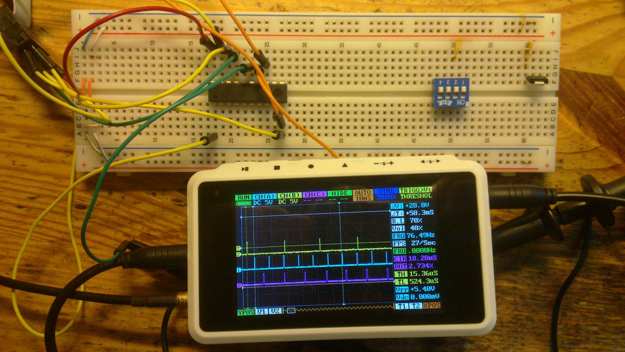
I apologize if this has been covered before, but searching isn't turning up anything relevant. With the latest teacup firmware, the PWM output pins to the heater FETs seem to always be putting out a minimum of roughly .020 volts, which is enough to dimly light the heater power LEDs and create a slight buzzing sound in a spindle I have hooked up to the heater pins. The cause seems to be the minimum on time of the PWM being 1 timer clock cycle, creating 1/256th of 5v (.020) instead of 0v on the pin, as specified in the datasheet:
And sure enough, when the heater pins are hooked up to an oscilloscope there's a 74Hz square wave which goes to 5v for a very brief period. The workaround seems to be turning off PWM completely instead of setting the PWM to zero. Is this a known issue with the firmware, or maybe considered a "feature"? This is the first board I've made, and I have no idea if everybody else is having their heater LEDs dimly lit from the moment the psu is first woken from standby.
Quote
The extreme values for the OCR0A Register represents special cases when generating a PWM waveform output in the fast PWM mode. If the OCR0A is set equal to BOTTOM, the output will be a narrow spike for each MAX+1 timer clock cycle.
And sure enough, when the heater pins are hooked up to an oscilloscope there's a 74Hz square wave which goes to 5v for a very brief period. The workaround seems to be turning off PWM completely instead of setting the PWM to zero. Is this a known issue with the firmware, or maybe considered a "feature"? This is the first board I've made, and I have no idea if everybody else is having their heater LEDs dimly lit from the moment the psu is first woken from standby.
|
Re: Project: Teacup Firmware July 23, 2012 05:59AM |
Registered: 13 years ago Posts: 7,616 |
Quote
The workaround seems to be turning off PWM completely instead of setting the PWM to zero. Is this a known issue with the firmware, or maybe considered a "feature"?
It's a known, but not really recognized status. Many electronics turn the power supply off while the electronics isn't in use, so the heater doesn't receive any voltage regardless of this 1/256 PWM.
That said, if you have a fix which doesn't slow normal operations and doesn't bloat the binary size, I'd happily apply it.
While you're working at it, currently Teacup initializes all available PWM outputs, IIRC. This could be improved to initialize only those of the configured pins. And also, heaters on non-PWM pins don't work with Teacup ...
| Generation 7 Electronics | Teacup Firmware | RepRap DIY |
|
Re: Project: Teacup Firmware August 09, 2012 03:13AM |
Registered: 11 years ago Posts: 9 |
Hi everyone!
I've been rewriting code for teacup for last few days. Basically i want to separate all modules in different files to make them work without weird ifdef constructions. Also to try clean up code, because it is too tight and depend on each other. As i see this project - there should be gcode parser alone and support for callback functions, there i can catch any gcode and do anything i want. For example if i have extruder i catch all his gcodes and execute them. If i have X stepper - i do same, even if i don't have all other steppers at all.
Reason for such modularity is simple - i can create small modules and connect them for example by i2c, and "main" module (which talk to computer) retransmit all g-codes to slave modules and wait till command executed.
As for now, i've moved analog, temperature, heater, watchdog, as well as split all temperature sensors types in separate files. Now i'm facing huge pile of code and macros in dda.c and pinio.c. And i see TODO note that all steppers should be in loop. Question is - does anybody will or have already rewritten this code to make a loop from it? Some of code i don't quite understand at all and i'm looking for help here.
Github fork: [github.com]
|
Re: Project: Teacup Firmware August 09, 2012 10:17AM |
Registered: 13 years ago Posts: 7,616 |
Great to see somebody working on Teacup. First thing I see is, well, you remove support for Gen3 electronics and support for ATmegas with built-in USB. Then you shuffle code around, remove the MEMORY_BARRIER safety measures and remove support for DC extruders, too. Uh.
Steppers have to be moved synchronized, so you can't handle them independently.
IMHO, a good first step whould be to make some types a union. For example, from ...
Quote
For example if i have extruder i catch all his gcodes and execute them.
Steppers have to be moved synchronized, so you can't handle them independently.
Quote
And i see TODO note that all steppers should be in loop. Question is - does anybody will or have already rewritten this code to make a loop from it?
IMHO, a good first step whould be to make some types a union. For example, from ...
typedef struct {
	// bresenham counters
	int32_t						x_counter;
	int32_t						y_counter;
	int32_t						z_counter;
	int32_t						e_counter;
totypedef struct {
// bresenham counters
union {
struct {
int32_t x_counter;
int32_t y_counter;
int32_t z_counter;
int32_t e_counter;
}
int32_t bresenham[NUM_AXIS];
}
Following such a path allows to change only parts of the code, making commits much more readable and not breaking everything if some pieces of the loop conversion are (intentionally or not) missed.| Generation 7 Electronics | Teacup Firmware | RepRap DIY |
|
Re: Project: Teacup Firmware August 09, 2012 10:34AM |
Registered: 11 years ago Posts: 9 |
Well, some of those things just commented out, i thought of moving it to other files. I know that this looks broken in most places, but i'll hopefully fix everything then overall structure will be defined and work correctly.
As for synchronization - if i send gcode in same time (almost, few cpu ticks later) to all modules, and every module do their job correctly - i think this would be pretty synchronized. Am i missing something?
As for synchronization - if i send gcode in same time (almost, few cpu ticks later) to all modules, and every module do their job correctly - i think this would be pretty synchronized. Am i missing something?
|
Re: Project: Teacup Firmware August 10, 2012 06:47AM |
Registered: 13 years ago Posts: 7,616 |
Well, I'd appreciate very much to bring improvements into mainstream Teacup, but shuffling around and deleting code without urgent reason makes this very difficult. Teacup is very modular already, a lot more than all other firmwares I'm aware of. Except GRBL, perhaps.
For one, this requires four independent timers, which the ATmega doesn't have in hardware. For two, you have to code very carefully to make sure the run time of all steppers matches. For three, you have to calculate all accelerations for each axis independently, requiring a lot more processing power. For four, acceleration of each axis has to be adjusted to match the target vector of the move.
Handling all four axes independently is actually a worthwhile goal, as this whould eventually allow jerk-free look-ahead, similar to how EMC2 works. First steps, solving the timer problem, are done and available, watch out for the code wrapped in ACCELERATION_TEMPORAL. Only acceleration-free movement there, so far.
Quote
if i send gcode in same time (almost, few cpu ticks later) to all modules, and every module do their job correctly
For one, this requires four independent timers, which the ATmega doesn't have in hardware. For two, you have to code very carefully to make sure the run time of all steppers matches. For three, you have to calculate all accelerations for each axis independently, requiring a lot more processing power. For four, acceleration of each axis has to be adjusted to match the target vector of the move.
Handling all four axes independently is actually a worthwhile goal, as this whould eventually allow jerk-free look-ahead, similar to how EMC2 works. First steps, solving the timer problem, are done and available, watch out for the code wrapped in ACCELERATION_TEMPORAL. Only acceleration-free movement there, so far.
| Generation 7 Electronics | Teacup Firmware | RepRap DIY |
|
Re: Project: Teacup Firmware August 10, 2012 06:49AM |
Registered: 13 years ago Posts: 7,616 |
P.S.: please don't let you stop playing around. Perhaps you see something I don't
| Generation 7 Electronics | Teacup Firmware | RepRap DIY |
|
Re: Project: Teacup Firmware August 10, 2012 07:11AM |
Registered: 11 years ago Posts: 9 |
Yeah, i'm sorry about deleted code, i'll restore it anyway - i've started to comment out it with FIXIT mark. Shuffling code i think is nesessary because for example max6675 sensor's code i found in several different places, which make this almost impossible to maintain or make changes. As for steppers, mostly my task at least is to split out code for extruder, to make them run independtly with separate atmega chip for each of them.
|
Re: Project: Teacup Firmware August 10, 2012 09:18AM |
Registered: 11 years ago Posts: 9 |
What if there would be only one hardware timer and code which makes from it software timers, like if i have a timer for 100ms and other for 150ms, i set up hardware to 100ms, wait for it, fire up first software callback, then set up hardware timer for 50ms, and wait for it. This will be a bit unaccurate if callback is taking a lot of time to complete, but worst what could happen is user will get his print few minutes later than expected. Or may be there is a way to compensate it. Do you see any problems with this approach so far?
|
Re: Project: Teacup Firmware August 10, 2012 09:51PM |
Registered: 16 years ago Posts: 1,094 |
x86_64 Wrote:
-------------------------------------------------------
> What if there would be only one hardware timer and
> code which makes from it software timers, like if
> i have a timer for 100ms and other for 150ms, i
> set up hardware to 100ms, wait for it, fire up
> first software callback, then set up hardware
> timer for 50ms, and wait for it.
Soupcup does this. Teacup and other firmwares run a bresenham algorithm that does something similar to this. It's perfectly feasible.
> This will be a
> bit unaccurate if callback is taking a lot of time
> to complete, but worst what could happen is user
> will get his print few minutes later than
> expected.
no, we simply add our delta to the previous trigger time instead of the current time, this way the interrupt latency doesn't affect the timing at all. The only issue is if the interrupt latency is so long (or the delta so short) that the new trigger time has already passed when the interrupt installs the new time- if that happens then the timer must overflow before it triggers.
To avoid this, it's useful to set a limit on the smallest delta potentially merging separate events into the same interrupt, or delaying events slightly, and accept that the timing won't be perfectly accurate in all cases. To get around that you need a more advanced chip with DMA, like cortex-m3
-----------------------------------------------
Wooden Mendel
Teacup Firmware
|
Re: Project: Teacup Firmware August 11, 2012 03:23AM |
Registered: 11 years ago Posts: 9 |
Didn't find such functionality in soupcup, maybe looked in wrong direction. Anyway, i've wrote software timers as i was intended to. It is here: [github.com]
New functions for setting up timer and enable/disable. Looks like it works fine (attach), at least i've tested it on attiny2313 with 1Mhz default clock for now. If you have time to test out on other hardware and/or with different timer settings - this would be really great. In meantime i'm starting to clean up dda into one axis mode with loop.
New functions for setting up timer and enable/disable. Looks like it works fine (attach), at least i've tested it on attiny2313 with 1Mhz default clock for now. If you have time to test out on other hardware and/or with different timer settings - this would be really great. In meantime i'm starting to clean up dda into one axis mode with loop.


Sorry, only registered users may post in this forum.