Project: Teacup Firmware
Posted by Triffid_Hunter
|
Re: Teensy 3.1 & Delta support February 07, 2015 06:38AM |
Registered: 10 years ago Posts: 14,672 |
Quote
Traumflug
For good printing results, acceleration/speed of the extruder matters. That said, all this approxximation with short segments is a bit a kludge, of course. I fear we can't avoid this kludge for now, making step-accurate movements curved and also properly accelerating and also constant velocity is pretty tricky.
All of this is entirely possible without kludge on a 32-bit processor, and implemented in my fork of RepRapFirmware. IMO it's a mistake to try to keep common code between 8 and 32 bit processors, because by doing so you lose the extra possibilities that 32 bit processors offer.
Edited 1 time(s). Last edit at 02/07/2015 06:55AM by dc42.
Large delta printer [miscsolutions.wordpress.com], E3D tool changer, Robotdigg SCARA printer, Crane Quad and Ormerod
Disclosure: I design Duet electronics and work on RepRapFirmware, [duet3d.com].
|
Re: Teensy 3.1 & Delta support February 07, 2015 06:45AM |
Registered: 13 years ago Posts: 7,616 |
Come on, @dc42, we wanted to discuss algorithms, see the other thread. :-) If you actually did this tricky code, please give me a hint on which parts these are and if it happens that this allows just 500 steps/second on the controller currently connected to my PC I promise you to connect a faster one tomorrow. It's already soldered.
| Generation 7 Electronics | Teacup Firmware | RepRap DIY |
|
Re: Teensy 3.1 & Delta support February 07, 2015 07:09AM |
Registered: 10 years ago Posts: 14,672 |
Traumflug, you can find all the movement code in modules Move, DDA and DriveMovement. The per-step calculations are done in DriveMovement. I have tested it up to 500mm/sec on my Mini Kossel with Duet electronics, and I think that is close to the limit on that hardware. You didn't say what controller you are using, so I can't comment on what speed you would achieve if you used the same algorithms.
Large delta printer [miscsolutions.wordpress.com], E3D tool changer, Robotdigg SCARA printer, Crane Quad and Ormerod
Disclosure: I design Duet electronics and work on RepRapFirmware, [duet3d.com].
Large delta printer [miscsolutions.wordpress.com], E3D tool changer, Robotdigg SCARA printer, Crane Quad and Ormerod
Disclosure: I design Duet electronics and work on RepRapFirmware, [duet3d.com].
|
Re: Teensy 3.1 & Delta support February 07, 2015 07:52AM |
Registered: 13 years ago Posts: 7,616 |
Quote
dc42
Traumflug, you can find all the movement code in modules Move, DDA and DriveMovement. The per-step calculations are done in DriveMovement.
Thanks.
Quote
dc42
You didn't say what controller you are using, so I can't comment on what speed you would achieve if you used the same algorithms.
Teacup shall get the best out of any controller. Being in an Arduino Nano, a RAMPS, a Teensy, or an Intel i7. Maybe even a Smoothieboard.
| Generation 7 Electronics | Teacup Firmware | RepRap DIY |
|
Shall we call it "1 Click Configuration"? February 08, 2015 06:30AM |
Registered: 13 years ago Posts: 7,616 |

|
Excursion to dc42 firmware February 10, 2015 05:44PM |
Registered: 13 years ago Posts: 7,616 |
Quote
dc42
Traumflug, you can find all the movement code in modules Move, DDA and DriveMovement.
Is it this repo? [github.com] Maybe not, because I can't find anything named DriveMovement in there.
:~/RepRap/RepRapFirmware$ grep -rn DriveMovement .
:~/RepRap/RepRapFirmware$ grep -rn DriveM .
:~/RepRap/RepRapFirmware$
Quote
dc42
I think that is close to the limit on that hardware.
In case it's this repo, uhm, no. But before explaining I want to make sure I looked at the right thing, first.
Edited 1 time(s). Last edit at 02/10/2015 05:47PM by Traumflug.
| Generation 7 Electronics | Teacup Firmware | RepRap DIY |
|
Re: Excursion to dc42 firmware February 10, 2015 06:53PM |
Registered: 10 years ago Posts: 14,672 |
That's the right repo, but the wrong branch. The code is in the dev branch. The master branch tracks RepRapPro's released version, although it may be a little out of date.
Large delta printer [miscsolutions.wordpress.com], E3D tool changer, Robotdigg SCARA printer, Crane Quad and Ormerod
Disclosure: I design Duet electronics and work on RepRapFirmware, [duet3d.com].
Large delta printer [miscsolutions.wordpress.com], E3D tool changer, Robotdigg SCARA printer, Crane Quad and Ormerod
Disclosure: I design Duet electronics and work on RepRapFirmware, [duet3d.com].
|
Re: Excursion to dc42 firmware February 10, 2015 09:07PM |
Registered: 13 years ago Posts: 7,616 |
Quote
dc42
That's the right repo, but the wrong branch. The code is in the dev branch.
Thanks, got it now. Experience with Teacup is, you hide you code pretty effectively this way, because 999 of 1000 lurkers don't care to ask and also don't look at other branches.
Quote
dc42
Traumflug, you can find all the movement code in modules Move, DDA and DriveMovement. The per-step calculations are done in DriveMovement.
Please correct me if I'm wrong, I see there one timer and you calculate time intervals not from one step of the fastest stepper to the next of the fastest stepper, but from one step to the next, no matter on which motor this next step happens. If two steppers should step at the same time, you call ScheduleInterrupt(0) (would be setTimer(0) in Teacup parlance). That's good, and I especially like this "repeat" flag!
The other thing is, I see the Delta -> Carthesian calculation as well as the acceleration calculation done for each step of each motor, just to find the next step interval. That's bold! That's like half a million square roots or more every second.
Quote
dc42
I have tested it up to 500mm/sec on my Mini Kossel with Duet electronics, and I think that is close to the limit on that hardware.
No surprise on this one. Total lack of optimisation and the about most computing intensive algorithm one could think of. On an ATmega one could sure be happy to reach 1000 steps/second.
| Generation 7 Electronics | Teacup Firmware | RepRap DIY |
|
Re: Excursion to dc42 firmware February 11, 2015 04:57AM |
Registered: 10 years ago Posts: 14,672 |
Quote
Traumflug
Please correct me if I'm wrong, I see there one timer and you calculate time intervals not from one step of the fastest stepper to the next of the fastest stepper, but from one step to the next, no matter on which motor this next step happens. If two steppers should step at the same time, you call ScheduleInterrupt(0) (would be setTimer(0) in Teacup parlance). That's good, and I especially like this "repeat" flag!
That's almost right. At each interrupt, the ISR checks all the DriveMovement objects to see which ones are due a step, based on the pre-calculated next step time. So if two motors are due a step at more or less the same time, both will get handled in one pass through the ISR and the repeat flag won't get used. The repeat flag comes into play when one motor wants a step slightly later, and it is not worth scheduling a separate interrupt.
I am considering modifying it by taking the DriveMovement objects out of the DDA. Then I can put them in their own queue, which can be ordered by the time of the next step. The ISR will pick off the DM at the head of the queue, do its step, and put it back in the correct position in the queue according to when it needs another step. This will be repeated as necessary, until the DM at the head of the queue isn't due a step for a while, then the next interrupt will be scheduled.
Quote
Traumflug
Total lack of optimisation and the about most computing intensive algorithm one could think of. On an ATmega one could sure be happy to reach 1000 steps/second.
Traumflug, I find that comment insulting. The algorithm calculates the step interval on a delta precisely (to better than 1us) instead of resorting to approximating linear moves in XYZ space as linear moves in delta space. If you can come up with a significantly better algorithm that achieves the same goal, please share it. As for optimisation, all the per-step calculations are done in integer maths. The square root function, which dominates the step interval calculation time, has been optimised by using a good algorithm and loop unrolling - but another user with ARM assembler experience is rewriting it in assembler to see if it can be speeded up further.
It is often said in software engineering circles that premature optimisation is the root of all evil - which is an exaggeration of course but contains more than a grain of truth. I have optimised the code sufficiently for the purpose for which it is intended, which is to drive 3D printers based on Duet or similar 32-bit electronics, leaving enough CPU cycles for the web interface, PanelDue etc. The 500mm/s I can achieve on a delta is significantly faster than most users want to use. I have no intention of trying to run it on an atmega or other 8-bit processor.
Edited 1 time(s). Last edit at 02/11/2015 06:53AM by dc42.
Large delta printer [miscsolutions.wordpress.com], E3D tool changer, Robotdigg SCARA printer, Crane Quad and Ormerod
Disclosure: I design Duet electronics and work on RepRapFirmware, [duet3d.com].
|
Re: Excursion to dc42 firmware February 11, 2015 06:16AM |
Registered: 13 years ago Posts: 7,616 |
Quote
dc42Quote
Traumflug
Total lack of optimisation and the about most computing intensive algorithm one could think of. On an ATmega one could sure be happy to reach 1000 steps/second.
Traumflug, I find that comment insulting. The algorithm calculates the step interval on a delta precisely (to better than 1us) instead of resorting to approximating linear moves in XYZ space as linear moves in delta space. If you can come up with a significantly better algorithm that achieves the same goal, please share it. As for optimisation, all the per-step calculations are done in integer maths. The square root function, which dominates the step interval calculation time, has been optimised by using a good algorithm and loop unrolling - but another user with ARM assembler experience is rewriting it in assembler to see if it can be speeded up further.
It is often said in software engineering circles that premature optimisation is the root of all evil - which is an exaggeration of course but contains more than a grain of truth. I have optimised the code sufficiently for the purpose for which it is intended, which is to drive 3D printers based on Duet or similar 32-bit electronics, leaving enough CPU cycles for the web interface, PanelDue etc. The 500mm/s I can achieve on a delta is significantly faster than most users want to use. I have no intention of trying to run it on an atmega or other 8-bit processor.
Sorry, didn't mean to be insulting. And you nicely describe how you didn't try to optimize ("instead of approximating").
As for optimisation opportunities, rewriting parts in assembler is the kind of optimisation I consider to be evil. Maybe you gain a few cycles but totally loose portability and readability. Compilers are very good at compiling to fast and efficient binaries, no need to mess with this.
Instead I'd try to reduce the required number of calculations. Earlier I suggested to do these caclulations only 500 times a second. If you fear this to be to coarse, do it 5000 times a second. This would still save 90% of all calculations if you move at 50'000 steps/s. It's also trickier, because you have to take care to not accumulate errors, but it can be done.
The Marlin/Smoothie approach of splitting paths into straight segments, then re-assembling them with running lookahead many many times is not exactly the most efficient strategy. Here I fully agree with you.
Another one is microoptimisation. Undoubtly something worth looking into for code which runs 100'000 times a second. Let's look at how you set an I/O pin. Platform:: SetHigh() checks for pin numbers, digitalWriteNonDue() looks up pin descriptions or whatever. That's already a lot better than the code on the master branch, still all these checks could be done at compile time and even if you want to have pin mappings runtime-configurable, a single check before starting the move is entirely sufficient.
For comparison: Teacup uses a macro for this, resulting in exactly two CPU instructions for doing the same. Your code already lost the race the moment it dereferences reprap.GetPlatform() to find the pin. Teacup implementation is WRITE() in arduino.h and x_step(), y_step()... in pinio.h.
Here's a series of commits which demonstrates how simple looping for code simplification can degrade performance up to 40%. "LED on time" means the time taken in the step interrupt, the first commit shows the original numbers.
[github.com]
[github.com]
[github.com]
[github.com]
[github.com]
| Generation 7 Electronics | Teacup Firmware | RepRap DIY |
|
Re: Excursion to dc42 firmware February 11, 2015 07:25AM |
Registered: 10 years ago Posts: 14,672 |
Quote
Traumflug
As for optimisation opportunities, rewriting parts in assembler is the kind of optimisation I consider to be evil. Maybe you gain a few cycles but totally loose portability and readability. Compilers are very good at compiling to fast and efficient binaries, no need to mess with this.
I agree, I prefer not to use assembler at all, mostly because of maintenance issues. Unfortunately, the code generated by the compiler (gcc 4.8.3, with optimisation -O3 for that section) generates code for the 64 bit integer square root that looks to me far from optimal. So unless I can find a way to modify the C++ source to get better code, I consider that rewriting that particular function in assembler is justified. Its function is fixed and unlikely to change, so it shouldn't cause any maintenance issues unless the code is ported to a non-ARM processor. An alternative I have considered is to limit the number of bits to about 44 instead of 64. That would make it possible to approximately double the speed.
I already considered speeding up the step high/step low functions by caching the I/O port details. However, the measurements I took indicate that part of the code is fast enough now. If I get the square root running faster, perhaps I will look at this again. One of the issues is that the A4982 chip specifies a minimum step pulse width of 1us, and if I make setting the port high/low too fast then I may violate this.
It would doubtless be possible to do the calculations less often and assume that the step interval doesn't change much over short periods of time, but why bother when the mcu is fast enough to do the full calculation on each step? As I have said elsewhere, I think 8-bit processors make no sense as 3D printer controllers any more. I looked up some prices. The atmega2560-16au (8 bit, 16MHz, 256K flash, 8K ram) 100 off costs £7.39. A similar size 32-bit processor, the atsam3s4c-cu (32 bit, 64MHz, 256Kflash, 48K RAM, US
 costs £3.24, less than half the atmega despite having 6 times the RAM and USB. Even the atsam3x8ea-au used on the Duet (32 bit, 84MHz, 512K flash, 96K RAM, USB, ethernet) at £5.61 costs less that the atmega2560. Need I say more?
Edited 2 time(s). Last edit at 02/11/2015 07:33AM by dc42.
Large delta printer [miscsolutions.wordpress.com], E3D tool changer, Robotdigg SCARA printer, Crane Quad and Ormerod
Disclosure: I design Duet electronics and work on RepRapFirmware, [duet3d.com].
|
Re: Excursion to dc42 firmware February 11, 2015 08:54AM |
Registered: 13 years ago Posts: 7,616 |
Quote
dc42
why bother when the mcu is fast enough to do the full calculation on each step? As I have said elsewhere, I think 8-bit processors make no sense as 3D printer controllers any more.
Trying to declare 8-bit controllers as obsolete is just like trying to declare gasoline cars as a thing of the past. People have them, people use them, and they're fast enough for carthesian kinematics. Your code works on one single controller (current Duet) and one single kinematics type (Deltas) only. There's a long way to go to make it universal.
Even if suddenly all controllers were 32-bit, what do you do when the next Duet comes with 1/128 microstepping drivers? Suddenly you're in a position much the same as 8-bits are now: you're limited in achievable printing speeds. And you still can't move Bezier curves, something undoubtly coming along sooner or later.
That's why it makes sense to write fast code. Improving algorithms helps both, 8-bit and 32-bit. That's why I laid my 32-bit controllers aside for a while until more important aspects are solved.
| Generation 7 Electronics | Teacup Firmware | RepRap DIY |
|
Re: Excursion to dc42 firmware February 11, 2015 09:38AM |
Registered: 10 years ago Posts: 14,672 |
Quote
Traumflug
Trying to declare 8-bit controllers as obsolete is just like trying to declare gasoline cars as a thing of the past.
I'm not declaring them as obsolete, just as inappropriate for the application, when 32-bit processors do the job faster and cost less. Designing a 3D printer around an 8-bit microcontroller now would be akin to buying a 1930s vintage car (costing double the price of a modern car) for the purpose of making a journey of several hundred miles on the motorway. I do use 8-bit microcontrollers for simple things where they are adequate and cost-effective, for example on my differential IR height sensing boards. I think the only reason RAMPS/Arduino remains popular is because nobody has designed, manufactured and aggressively marketed a RAMPS-like board with an embedded ATSAM3S4C or similar processor. That would be significantly cheaper to manufacture than Arduino + RAMPS, as well as more capable.
Quote
Traumflug
Your code works on one single controller (current Duet) and one single kinematics type (Deltas) only.
It does Cartesian as well. I believe it would be trivial to add CoreXY, but I don't have a CoreXY rig to test it on. The hardware dependencies are confined to the Platform module and the libraries that calls, so it shouldn't be hard to port to other 32-bit hardware, if anyone wants to.
Quote
Traumflug
Even if suddenly all controllers were 32-bit, what do you do when the next Duet comes with 1/128 microstepping drivers? Suddenly you're in a position much the same as 8-bits are now: you're limited in achievable printing speeds.
If/when that happens, I'll look into your most helpful suggestion of calculating the step intervals rather less often than on every step. For now at least, I don't need to do that and accept the approximations that it involves.
Large delta printer [miscsolutions.wordpress.com], E3D tool changer, Robotdigg SCARA printer, Crane Quad and Ormerod
Disclosure: I design Duet electronics and work on RepRapFirmware, [duet3d.com].
|
Re: Excursion to dc42 firmware February 11, 2015 01:39PM |
Registered: 13 years ago Posts: 7,616 |
Quote
dc42
I'm not declaring them as obsolete, just as inappropriate for the application
I see. It's pointless to try to get 32-bit fans into joining writing fast and efficient code.
| Generation 7 Electronics | Teacup Firmware | RepRap DIY |
|
Re: Excursion to dc42 firmware February 11, 2015 02:03PM |
Registered: 10 years ago Posts: 14,672 |
Quote
Traumflug
Quote
dc42
I'm not declaring them as obsolete, just as inappropriate for the application
I see. It's pointless to try to get 32-bit fans into joining writing fast and efficient code.
My current code is fast enough to run a 3D printer at high speeds (cheaper than the atmega2560) on a cheap (cheaper than the atmega2560) microcontroller using a mathematically-precise (to about 1us) algorithm. So what would be the point of spending more time and sacrificing movement precision in order to make it faster? I have better things to do with my time, for example I've just implemented near-instant pausing of prints and automatic running of pause and resume macros. This will make it easy for me to e.g. embed a nut or other metal part in a print.
I understand that you want your Teacup firmware to run on a wide variety of hardware, including what I consider legacy hardware. If that's your goal, then fine. My goal is different: to get good performance out of Duet and similar hardware, and to add features that improve functionality, productivity and safety. Over-optimising the movement code won't contribute to that goal unless and until I have a need for extra performance.
Edited 1 time(s). Last edit at 02/11/2015 02:03PM by dc42.
Large delta printer [miscsolutions.wordpress.com], E3D tool changer, Robotdigg SCARA printer, Crane Quad and Ormerod
Disclosure: I design Duet electronics and work on RepRapFirmware, [duet3d.com].
|
Re: Excursion to dc42 firmware February 11, 2015 02:20PM |
Registered: 13 years ago Posts: 7,616 |
Quote
dc42
My current code is fast enough to run a 3D printer at high speeds
Same here. I need 25'000 steps/second and Teacup delivers 48'000 on 8-bit. Still I continue to develop. Simply because it's fun.
Quote
dc42
(cheaper than the atmega2560) on a cheap (cheaper than the atmega2560) microcontroller
People should be very interested where you get these controllers. Or how you leverage the processing speed of a cheap CPU without expensive controller around it. To the best of my knowledge, there are no such things. Even the affordable Teensy3 is more than double the price of an comparable Arduino Nano.
| Generation 7 Electronics | Teacup Firmware | RepRap DIY |
|
Re: Excursion to dc42 firmware February 13, 2015 08:37AM |
Registered: 10 years ago Posts: 14,672 |
Quote
Traumflug
Quote
dc42
on a cheap (cheaper than the atmega2560) microcontroller
People should be very interested where you get these controllers. Or how you leverage the processing speed of a cheap CPU without expensive controller around it. To the best of my knowledge, there are no such things. Even the affordable Teensy3 is more than double the price of an comparable Arduino Nano.
Right now, there appears to me to be a huge gap in the market for an affordable (similar price to Arduino Mega + RAMPS) 32-bit 3D printer controller board. I might just do something about that. There is no need for what you call an "expensive controller" around the CPU.
Edited 1 time(s). Last edit at 02/13/2015 08:37AM by dc42.
Large delta printer [miscsolutions.wordpress.com], E3D tool changer, Robotdigg SCARA printer, Crane Quad and Ormerod
Disclosure: I design Duet electronics and work on RepRapFirmware, [duet3d.com].
|
Re: Project: Teacup Firmware February 15, 2015 07:16AM |
Registered: 10 years ago Posts: 91 |
Hey dc42,
I've got a similar algorithm for step timing in my APrinter firmware. Seems like we're both tying to precisely calculate the step times using square roots.
But I think the difference is that I normalize the calculation to the duration of the move (segment with fixed acceleration), and only at the end perform a multiplication with the move-duration to get the final step time. My motivation for this was to reduce the ranges that need to be handled in the computation. In particular I use square root with much less bits (26-bit).
For the integer square root computation, I've implemented it in C++ with templates to unroll the loop at compile time. In my case of a 26-bit square root, it compiles to this. Can you tell with a quick look if this is good?
The source for this square root here. Note that there's two versions, a faster one used for most bit-counts, and a slightly slower one for 7,8,15,16,31,32,63,64-bits, since it needs to handle overflows.
My actual stepping code is here, but it's hard to read due to lack of comments and heavy use of templates.
Edited 4 time(s). Last edit at 02/15/2015 07:21AM by ambrop7.
|
An excursion to aprinter firmware :-) February 15, 2015 09:24AM |
Registered: 13 years ago Posts: 7,616 |
@ambrop7, I certainly had a look at aprinter already and the very nice thing is, it doesn't make heavy assumptions on bit-width of the CPU. It also led me to the conclusion that C++11 is an entire new language I have yet to learn, no longer a derviate of C. So yes, currently it isn't decipherable by me, as much as I'd like to read it.
| Generation 7 Electronics | Teacup Firmware | RepRap DIY |
|
Re: Project: Teacup Firmware February 15, 2015 10:32AM |
Registered: 9 years ago Posts: 9 |
@dc42 and @ambrop7,
Looking at your firmwares, I am trying to get the flow of what is happening, but it looks like it will take hours of code analysis
Can you please give me a simple flowchart or pseudocode of the steps being taken to calculate the step times?
I would appreciate it very much!
Looking at your firmwares, I am trying to get the flow of what is happening, but it looks like it will take hours of code analysis
Can you please give me a simple flowchart or pseudocode of the steps being taken to calculate the step times?
I would appreciate it very much!
|
Re: Project: Teacup Firmware February 15, 2015 12:49PM |
Registered: 10 years ago Posts: 91 |
So, as per request, here's a description of the step time calculation algorithm used in APrinter.
Note that it may have some errors and some details of the implementation may have been left out.
Suppose we want to move in a constantly-accelerated manner, with the following parameters:
X[step] - Length of the move in steps.
T[tick] - Duration of the move.
A[step/tick^2] - Acceleration.
These parameters are generated for each constant-acceleration segment by the planning algorithm, and for each stepper individually.
Usually each linear move is split into 3 such segments (acceleration, constant speed, deceleration).
Let's begin with the classic equation of accelerated motion, relating a particular position 'x' with a particular time 't'.
x = V0*t + (A/2)*t^2
Here, V0=(X-(A/2)*T^2)/T, is the initial velocity, obtained by substituting x=X and t=T in the above equation.
The problem is the calculation of the times 't' when individual steps should take place.
These are the solutions 't' of the above quadratic equation where 'x' is an integer in the range [0, X].
However, before bringing in the quadratic formula, let's transform the problem so that the core calculations are done relative to the total time T. We introduce the transformed acceleration:
A'[step] = (A/2)*T^2 (we also divide by two because that will make things simpler)
By substituting this in the motion equation, and some factoring, we can arrive at:
x = V0'*f + A'*f^2
Where:
- V0'[step] = V0*T = X-A' (transformed initial velocity)
- f[1] = t/T (relative time)
With the assumption that the direction of motion does not change within the segment, we can calculate the
permitted range of A'. It comes out very nicely: A' is in [-X, X]. Notable cases are:
- A'=0 - A constant-velocity move.
- A'=X - A move which start at zero velocity and accelerates.
- A'=-X - A move which which decelerates and stops at zero velocity.
This nice bounded nature of A' makes it a good choice for an input parameter, and in APrinter the planning algorithm does in fact spit out segments defined by (X, T, A').
Knowledge of this bound is also very helpful for the implementation with fixed-point arithmetic.
In APrinter, A' is an *integer*, which seems to be a good precision.
In this transformed space we will express the relative-step-time solution 'f' using the quadratic formula.
However to avoid loss of significance with small or zero accelerations,
we use an alternative solution form that follows from Vienna's formulas.
For details, see [en.wikipedia.org] , the "x2=c/(a*x1)" formula, and substitute the "minus square root" version of the classic solution expression for x1.
In the end, we can arrive at:
f = x / (2 * (V0' + sqrt(V0'^2 + 4*A'*x)))
The efficient calculation for subsequent steps can be performed with an algorithm like this:
Initialization:
V0' := X-A'
x := 0
D := V0'^2
Dstep := 4*A'
Then for each step:
x := x + 1
D := D + Dstep
t = T * (x / (2 * (V0' + sqrt(D))))
Note that these formulas provide less precision for accelerating moves, because the dividend in the time calculation will be smaller,
so the error in integer square root computation will have a larger effect on the result. But see how for decelerating moves (A'<=0), we have V0'>=X, and therefore the dividend is always reasonably large.
So it makes sense to treat accelerating moves as symmetric decelerating moves (invert A', iterate 'x' from X down to 0, invert the resulting time),
For performance reasons, it makes sense to limit the range of X (and consequently A'), and have the planning algorithm split moves into parts that don't exceed the limit. This is because a limited range reduces the required bit width for variables and operations.
The default in APrinter is 12 bits for X (a single move can be no longer than 4096 steps), and only a 26-bit integer square root.
It's a bit of magic tuning the precisions/bit-widths to get a sufficiently precise output. But some observations help:
- The calculation of V0', Dstep, D, D+Dstep can be exact.
- The (relative) velocity is at no single point larger than twice the average velocity over the segment (2*X). This is easy to see by computing the starting/ending velocity of an A'=-X or A'=X segment respectively.
- At the least one wants to obtain different 'f' for different 'x'.
- Combining the above two, it follows that the number of bits used for the fractional value 'f' should be at least one more than the number of bits used for 'X'.
- One can reduce the number of bits to represent T, as long as the resulting error is small compared to the error in the computation of 'f'.
Edited 12 time(s). Last edit at 02/15/2015 05:30PM by ambrop7.
|
Re: Project: Teacup Firmware February 15, 2015 04:11PM |
Registered: 10 years ago Posts: 14,672 |
Quote
NickE
@dc42 and @ambrop7,
Looking at your firmwares, I am trying to get the flow of what is happening, but it looks like it will take hours of code analysis
Can you please give me a simple flowchart or pseudocode of the steps being taken to calculate the step times?
I would appreciate it very much!
I'm on a mobile, so excuse my brevity. RepRapFirmware does no segmentation because there is no reason to. The GCodes module sets up the data for each linear move, which is picked up by the Move module. This finds an empty DDA and calls DDA::Init to set it up. That in turn calls the lookahead function.
When a DDA record gets close to its time for execution, Move calls DDA:: Prepare on it. This freezes the record so that lookahead can no longer change it, and calculates and stores the integer variables needed to compute the step times. Prior to that, floating point maths is mostly used. It also calls the DriveMovement::Calculate function on each drive to store the time from the start of the move to the time of the first step for that drive.
When the system wants to start a move, it schedules an interrupt for the time of the first step needed for that move. At each interrupt , it checks each drive to see if a step is due, if so it generates a step and calls DriveMovement::Calculate to work out the time of the next step. When all drives are done, it schedules an interrupt for when the next step is now due.
The calculations depend on whether the drive is a Cartesian motor drive, a Delta motor drive, or an extruder drive with Bowden elasticity compensation. In general, the acceleration/deceleration and Delta calculations need to take the square root of a number larger than 32 bits. Currently I use a 64-bit square root function and this is fast enough for moves up to at least 500mm/sec on the Mini Kossel with 1/16 microstepping. But 48 bits is almost certainly enough, so I may make some changes in that area.
Hope this helps dc42
Edited 2 time(s). Last edit at 02/15/2015 04:15PM by dc42.
Large delta printer [miscsolutions.wordpress.com], E3D tool changer, Robotdigg SCARA printer, Crane Quad and Ormerod
Disclosure: I design Duet electronics and work on RepRapFirmware, [duet3d.com].
|
Re: Project: Teacup Firmware February 16, 2015 01:33PM |
Registered: 9 years ago Posts: 9 |
|
Re: Project: Teacup Firmware February 16, 2015 01:49PM |
Registered: 9 years ago Posts: 9 |
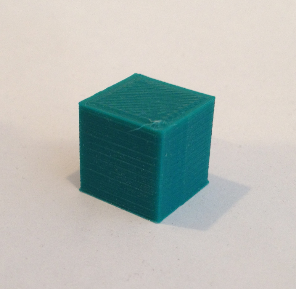
Teacup now supports Delta Kinematics!
Today, I was able to successfully do a test print using Teacup.
It is only the lowly 15mm test cube done at 30mm/s, but it is the culmination of many hours of effort.
I know, I know - without evidence, it didn't happen:
YouTube
[please excuse my test bench, it is a disaster!]
Also see attached picture of the finished test cube.
Rudimentary LCD support for the RepRapDiscount Smart Controller has also been added.
Right now, only the config.ramps-v1.3.h has the necessary defines to make it work, since all testing has been done on the RAMPS1.4/Mega Platform. The necessary defines will be added to the other platforms soon.
The current version of the firmware is still very rough. Refinement will continue...
|
Re: Project: Teacup Firmware February 16, 2015 05:28PM |
Registered: 13 years ago Posts: 7,616 |
|
Re: Project: Teacup Firmware February 21, 2015 10:28PM |
Registered: 9 years ago Posts: 1 |
Hello Everyone
Newbie here, so please allow me to introduce myself. My real name is Bruce and my user name is P8X32A.
I am currently in the process of attempting a Teacup firmware port, which will enable Teacup to run on Parallax's Propeller uC, which is the P8X32A. I chose the Propeller chip long ago, because it has 32 IO pins, 8 processors (cogs) that can run in parallel, and it has a system clock that can run in excess of 80MHZ. I have built several things using the Propeller chip, but my 3D printer project is by far the most interesting.
When I started the port, a little over two weeks ago, I was initially going in circles, because of indecisiveness, and a true lack of understanding pertaining to the firmware. I am now happy to say, that I am finely getting a good overview of the firmware and that there is finally progress in a positive direction. Let me just say that the Teacup firmware is a fine piece of programming. Anyhow, considering the major differences in architecture, between Arduino and Parallax's Propeller, I been tearing the Teacup firmware to shreds, with no intention of insulting anyone. What might be a golden nugget to the Arduino family, is in many cases quite useless to the Propeller. So please don't take offense, if you read my thread and see the word garbage or junk, when I actually know that it is good code for Arduino For those that may be interested in following along with this, you can find that information here: Teacup to Propeller port
And here is a photo of my controller built from the Propeller
Information about the controller can be found at this forum thread: Controller thread
Additionally here are some photos of my custom built extruder :
And here are some components that I will be using on the printer (the big white box is a 48VDC PSU with several options)
For more general information about me, you can visit my website here: Novel Solutions website
Well anyhow, that is enough about. I look forward to many in depth discussions and the sharing of ideas. For now, it looks like I have a lot of reading to do, pertaining to previous posts.
Pleased to make your acquaintance everyone.
Bruce
Newbie here, so please allow me to introduce myself. My real name is Bruce and my user name is P8X32A.
I am currently in the process of attempting a Teacup firmware port, which will enable Teacup to run on Parallax's Propeller uC, which is the P8X32A. I chose the Propeller chip long ago, because it has 32 IO pins, 8 processors (cogs) that can run in parallel, and it has a system clock that can run in excess of 80MHZ. I have built several things using the Propeller chip, but my 3D printer project is by far the most interesting.
When I started the port, a little over two weeks ago, I was initially going in circles, because of indecisiveness, and a true lack of understanding pertaining to the firmware. I am now happy to say, that I am finely getting a good overview of the firmware and that there is finally progress in a positive direction. Let me just say that the Teacup firmware is a fine piece of programming. Anyhow, considering the major differences in architecture, between Arduino and Parallax's Propeller, I been tearing the Teacup firmware to shreds, with no intention of insulting anyone. What might be a golden nugget to the Arduino family, is in many cases quite useless to the Propeller. So please don't take offense, if you read my thread and see the word garbage or junk, when I actually know that it is good code for Arduino
For those that may be interested in following along with this, you can find that information here: Teacup to Propeller portAnd here is a photo of my controller built from the Propeller
Information about the controller can be found at this forum thread: Controller thread
Additionally here are some photos of my custom built extruder :
And here are some components that I will be using on the printer (the big white box is a 48VDC PSU with several options)
For more general information about me, you can visit my website here: Novel Solutions website
Well anyhow, that is enough about. I look forward to many in depth discussions and the sharing of ideas. For now, it looks like I have a lot of reading to do, pertaining to previous posts.
Pleased to make your acquaintance everyone.
Bruce
|
Re: Project: Teacup Firmware April 17, 2015 08:01PM |
Registered: 13 years ago Posts: 87 |
Been following the latest discussions here, thought I'd throw in my own 2c...
Not sure if anyone's interested but I did a write-up a few years ago on the maths used in my own Repic firmware, see [reprap.org] for details. It does proper RepRap 5D interpolation with zero error. The basic idea is that it does an iterative integral of both the position and velocity terms using 1:31 fixed-point math but calculates the total round-off error in advance and adds an additional error term to compensate (implement with Brensenham's line algorithm). End result is perfect extrusion down to the individual cycle.
On a totally unrelated note I haven't been able to find any implementations of teacup that print off SD card? I see there's support for writing to SD but not printing, have I missed something or has it just not been added yet?
Edited 1 time(s). Last edit at 04/17/2015 08:07PM by Myndale.
|
Re: Project: Teacup Firmware April 17, 2015 08:37PM |
Registered: 13 years ago Posts: 7,616 |
Quote
Myndale
Not sure if anyone's interested but I did a write-up a few years ago on the maths used in my own Repic firmware
If you think there's a performance or precision gain to leverage, feel free to stuff this in. I'll happily give you write access, so you can put it right into the main repo. To find the places which need tweaking, watch out for #ifdefs with ACCELERATION_TEMPORAL.
Current interrupt times are somewhere between 310 and 370 clock cycles per step. Even equipment for cycle-accurate performance/accuracy measurements are in place, see the currently second last commit on the experimental branch for starters.
Quote
Myndale
I haven't been able to find any implementations of teacup that print off SD card? I see there's support for writing to SD but not printing, have I missed something or has it just not been added yet?
There is code on the sdcard2 branch which implements reading, but not yet writing. Writing will be easy to add as well. The latest test report spoke about a bug, I still didn't build me the hardware to test this.
| Generation 7 Electronics | Teacup Firmware | RepRap DIY |
|
Re: Project: Teacup Firmware April 22, 2015 01:23PM |
Registered: 10 years ago Posts: 8 |
Myndale,
I just saw your post about the Repic5D software. I was intrigued so I looked over the page on reprap.
I had a couple questions on it if you don't mind. Have you used it much and how well does it perform? Are you still developing it or is it currently abandoned? Any known issues with it?
I noticed it looked like you were doing much of the calculations on the host and only passing certain data elements to firmware. I had started a thread kind of related here about such a topic. [forums.reprap.org]
Any insight you could give on it would be helpful as I was venturing down a similar path.
Thanks,
Chris
|
Re: Project: Teacup Firmware April 22, 2015 02:49PM |
Registered: 13 years ago Posts: 7,616 |
Quote
nilrods
Repic5D software. [...] I had a couple questions on it if you don't mind.
Please ... this is the Teacup Firmware thread.
Quote
nilrods
[forums.reprap.org]
Actually, Teacup supports this already, it's ACCELERATION_REPRAP in Configtool / config.h.
| Generation 7 Electronics | Teacup Firmware | RepRap DIY |


Sorry, only registered users may post in this forum.