LPC port of RepRapFirmware
Posted by sdavi
|
Re: LPC port of RepRapFirmware December 17, 2019 04:24AM |
Registered: 12 years ago Posts: 224 |
|
Re: LPC port of RepRapFirmware December 17, 2019 11:12PM |
Registered: 10 years ago Posts: 341 |
|
Re: LPC port of RepRapFirmware December 18, 2019 01:21AM |
Registered: 6 years ago Posts: 110 |
Anyone tried using an IR Probe with the LPC port? How did you configure it?
I can only get it to work in analog mode. I suspect its might be because I have not defined the modulation in board.txt but I am not sure.
I tried
but I could not see any change in DWC when I triggered the probe. then I changed it to
from my board.txt file-
I looked at both dc42' blog page and the Duet docs- [duet3d.dozuki.com]
I tried Modes 1, 2, 4 and 8. Same results: I dont get a status change in DWC or from M119 when I manually trigger the probe with a piece of paper.
Any suggestions?
tia
Dennis
I can only get it to work in analog mode. I suspect its might be because I have not defined the modulation in board.txt but I am not sure.
I tried
M558 P1 H5 F120 T6000 ; DID NOT WORK set Z probe type to modulated and the dive height + speeds
but I could not see any change in DWC when I triggered the probe. then I changed it to
M558 P4 C2 F360 T6000 H3 R0.5           ; SET IR PROBE AS AN ON-OFF SWITCH
G31 P500 X0 Y31.5 Z1.5                 ; set Z probe trigger value, offset and trigger height
from my board.txt file-
//RRF equiv       X     Y    Z     E0    E1    E2
//RRF C Index     0     1    2     3      4     5
//                       Xmin  Ymin  Zmin  Xmax  Ymax  Zmax
endstop.pins = {1.24, 1.26, 1.29, 1.25, 1.27, 1.28};

// Z Probe pin
// Probe pin can be NoPin and select from an "EndStop Pin"
// (which are digital input)
// using the C parameter of M558.
// Note: Expected to be an ADC pin for certain modes,
// if needed then a spare A/D capable pin should be used and set zProbe.pin below. Beware that pins configured for
// ADC are **NOT** 5V tolerant
zProbe.pin = 1.29;
zProbe.modulationPin = NoPin;
(I know that we only use 3 of the endstops as defined and the nMAX is redundant, but I left them as originally written)I looked at both dc42' blog page and the Duet docs- [duet3d.dozuki.com]
I tried Modes 1, 2, 4 and 8. Same results: I dont get a status change in DWC or from M119 when I manually trigger the probe with a piece of paper.
Any suggestions?
tia
Dennis
|
Re: LPC port of RepRapFirmware December 18, 2019 02:44AM |
Registered: 10 years ago Posts: 341 |
1.29 is not ADC capable, if you need analog then you need to find a spare ADC pin and use that pin for zProbe.pin. Pins configured as ADC inputs are not 5V tolerant.
Generally I'd expect most people on the LPC port to use digital type probes with either P5, P8 or P9 and set zProbe.pin to the endstop pin they want to use as the probe (and remove that pin from the endstop array and replace with NoPin) as most people will use z-min or z-max endstop connector. When the docs refers to the "z-probe connector", then set zProbe.pin.
i.e.
If that's DC42s IR probe, then its probably going into digital mode (led flashes 2 times) as there is normally a pullup resistor on the endstop pins on the LPC boards. Using the board config like above with P5 probe type I think should work.
Edited 1 time(s). Last edit at 12/18/2019 02:50AM by sdavi.
Generally I'd expect most people on the LPC port to use digital type probes with either P5, P8 or P9 and set zProbe.pin to the endstop pin they want to use as the probe (and remove that pin from the endstop array and replace with NoPin) as most people will use z-min or z-max endstop connector. When the docs refers to the "z-probe connector", then set zProbe.pin.
i.e.
endstop.pins = {1.24, 1.26};
zProbe.pin = 1.29;
If that's DC42s IR probe, then its probably going into digital mode (led flashes 2 times) as there is normally a pullup resistor on the endstop pins on the LPC boards. Using the board config like above with P5 probe type I think should work.
Edited 1 time(s). Last edit at 12/18/2019 02:50AM by sdavi.
|
Re: LPC port of RepRapFirmware December 18, 2019 10:39PM |
Registered: 6 years ago Posts: 110 |
Sometimes I really like the dozuki documentation, then sometimes I hate it because I think its missing the basic info.
1. Going the route of the [configtool.reprapfirmware.org] selecting the 'Unmodulated or Smartr IR Probe' spits this out- Analog with HIGH signal.
2. [duet3d.dozuki.com]
P5 is Digital connected to Zprobe input, HIGH for probing, LOW at other times
P8 is unfiltered digital connected to Zprobe input, same as P5.
P4 mode is digital connected to E0 endstop, OR endstop set by the C parameter.
3. This is what I am currently using-
and that almost makes no sense to me because it reads like and analoge switch on the PanelDue. Its either 0 or 1000
I will keep at it.
1. Going the route of the [configtool.reprapfirmware.org] selecting the 'Unmodulated or Smartr IR Probe' spits this out- Analog with HIGH signal.
M558 P1 H5 F120 T6000 ; set Z probe type to unmodulated and the dive height + speeds
2. [duet3d.dozuki.com]
P5 is Digital connected to Zprobe input, HIGH for probing, LOW at other times
P8 is unfiltered digital connected to Zprobe input, same as P5.
P4 mode is digital connected to E0 endstop, OR endstop set by the C parameter.
3. This is what I am currently using-
M558 P4 C2 F360 T6000 H3 R0.5 ; SET IR PROBE AS AN ON-OFF SWITCH
and that almost makes no sense to me because it reads like and analoge switch on the PanelDue. Its either 0 or 1000
I will keep at it.
|
Re: LPC port of RepRapFirmware December 18, 2019 11:25PM |
Registered: 10 years ago Posts: 341 |
Quote
sinned
Its either 0 or 1000
That's still a digital signal (only on or off), if it were analog you'd be getting values in-between as well
 . Its just the way its represented - probes have a value between 0 and 1000 for both analog or digital types.
Edited 2 time(s). Last edit at 12/18/2019 11:36PM by sdavi.
|
Re: LPC port of RepRapFirmware December 19, 2019 01:11AM |
Registered: 6 years ago Posts: 110 |
wow, i really misundertstood this. I will try again
EDIT: I think I have this figured out.
I did not understand how the analog signal worked compared to the digital. For some reason, I had it in my head that analog was either OFF or ON => 0 or 1000.
The conventional endstop pins are digital GPIO pins. 1.24, 1.25, 1.26 ... 3.3V
The reprap configurator will spit this out as the ideal config for the Smart IR board - M558 P1 but Mode 1 is ANALOG!
Mode 4 is digital assigned to whatever pin you set via the C parameter or E0, which is digital. And this works because pin 1.29 which in my case is mapped to Zmin header is digital.
Mode 5 is a filtered digital device on the assigned Z probe, and its digital
Mode 8 is a unfiltered digital device on the assigned Z probe and also digital.
The part about 5V tolerant has me confused too. Isn't the logic on the LPC board at 3.3V? Our endstops that are on 1.25, 1.25, 1.26... all are on 3.3v.
So what I think is being cautioned is don't connect the Signal and GND from the Smart IR cable to the endstop header and connect the V+ to 5V because the signal coming from the IR board will be 5V not 3.3V, and pins 1.24/1.25/1.29 are not 5V tolerant..
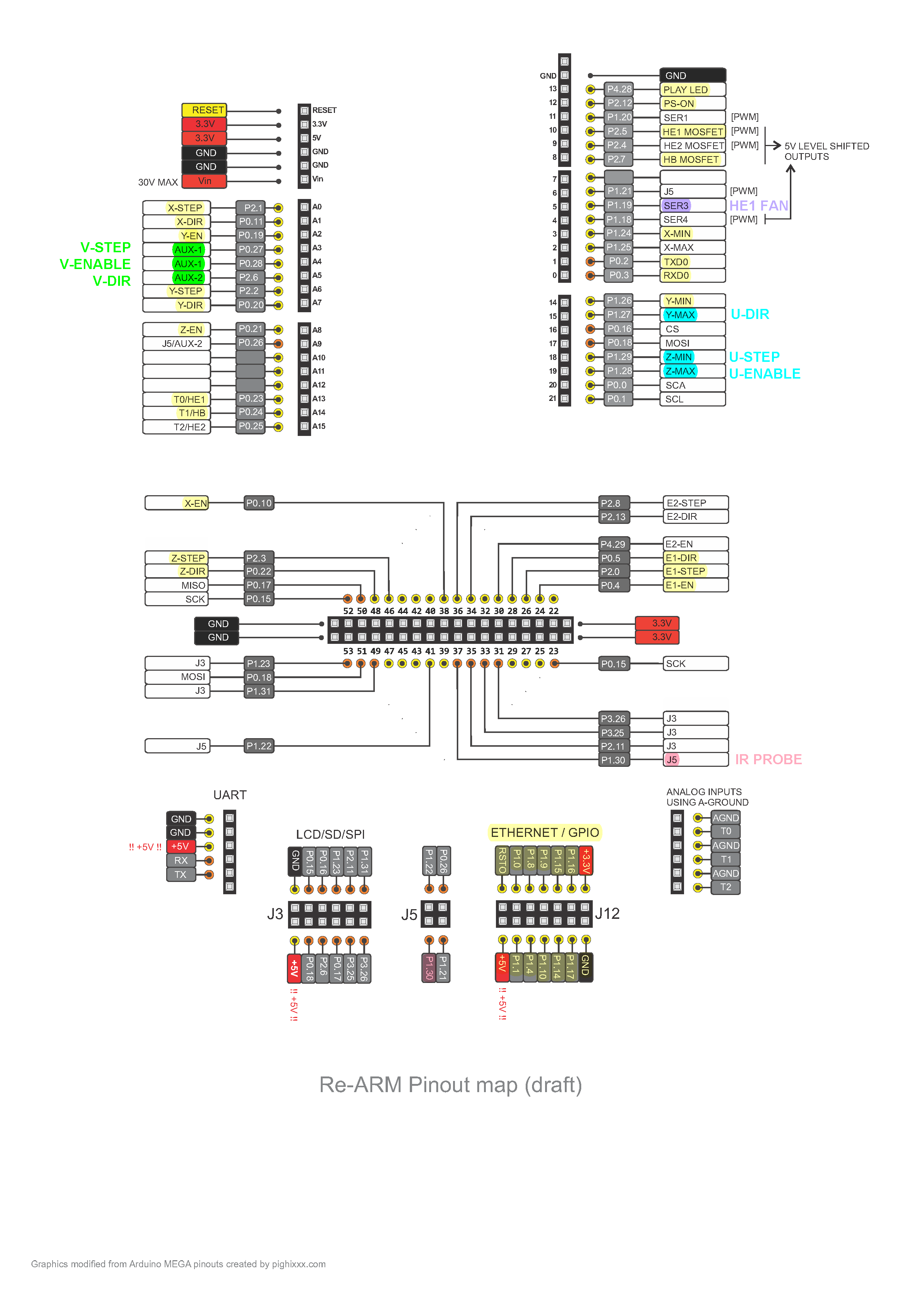
If i am understanding the LPC docs, the analog pins are marks ADx-here is a snippet of the pin description superimposed on a pin diagram. There are a total of 6 possible pins if they are not used.
So to use the analog Mode 1, the Smart IR needs to be fed +5V from somewhere, and the Signal and GND wires get connected to say the HE2 thermistor input. The +5V voltage can come from the same place that the LCD or servo would have gotten power from.
I'd really appreciate it if someone could comment on my understanding and scheme, I would appreciate it.
Edited 1 time(s). Last edit at 12/20/2019 03:47AM by sinned.
EDIT: I think I have this figured out.
I did not understand how the analog signal worked compared to the digital. For some reason, I had it in my head that analog was either OFF or ON => 0 or 1000.
The conventional endstop pins are digital GPIO pins. 1.24, 1.25, 1.26 ... 3.3V
The reprap configurator will spit this out as the ideal config for the Smart IR board - M558 P1 but Mode 1 is ANALOG!
Mode 4 is digital assigned to whatever pin you set via the C parameter or E0, which is digital. And this works because pin 1.29 which in my case is mapped to Zmin header is digital.
Mode 5 is a filtered digital device on the assigned Z probe, and its digital
Mode 8 is a unfiltered digital device on the assigned Z probe and also digital.
The part about 5V tolerant has me confused too. Isn't the logic on the LPC board at 3.3V? Our endstops that are on 1.25, 1.25, 1.26... all are on 3.3v.
So what I think is being cautioned is don't connect the Signal and GND from the Smart IR cable to the endstop header and connect the V+ to 5V because the signal coming from the IR board will be 5V not 3.3V, and pins 1.24/1.25/1.29 are not 5V tolerant..
If i am understanding the LPC docs, the analog pins are marks ADx-here is a snippet of the pin description superimposed on a pin diagram. There are a total of 6 possible pins if they are not used.

So to use the analog Mode 1, the Smart IR needs to be fed +5V from somewhere, and the Signal and GND wires get connected to say the HE2 thermistor input. The +5V voltage can come from the same place that the LCD or servo would have gotten power from.
I'd really appreciate it if someone could comment on my understanding and scheme, I would appreciate it.
Edited 1 time(s). Last edit at 12/20/2019 03:47AM by sinned.
|
Re: LPC port of RepRapFirmware December 21, 2019 07:13PM |
Registered: 6 years ago Posts: 110 |
Quote
sinned
So to use the analog Mode 1, the Smart IR needs to be fed+5V3.3Vfrom somewhere, and the Signal and GND wires get connected to say the HE2 thermistor input. The +5V voltage can come from the same place that the LCD or servo would have gotten power from.
I'd really appreciate it if someone could comment on my understanding and scheme, I would appreciate it.
I separated the Signal wire from the loom and plugged it onto pin 1.30
I changed the M5558 to read-
M558 P1 H5 F120 T6000
in board.txt I changed the pin assignment to read -
endstop.pins = {1.24, 1.26};

ZProbe.pin = 1.30;
and now when it starts up, the sensor blinks 4 times, which indicated analog mode. I tweaked the Z trigger height a touch and now when I probe, it starts moving and then as the probe gets closer to the nozzle, it slows down to about half the speed as it approaches the nozzle.
SNow however, them thermostatically controlled fan runs all the time and the back of the bed read 1mm low across the entire bed.

EDIT: I got everything worked out -
1. HE1 thermostatically controlled fan was goof on my part. Rewiring it made it all better
2. Back of the bed was actually the front of the bed, and it was because the sensor was off the PEI-
the realtive positions of the sensor are + / - dependent. Initially I think I mis-used the Marlin position signs instead of relative to the nozzle. Once I got the location correct, then I defined the bed probing locations and number of probes and then I was of to the races.
G31 P500 X0 Y-31.5 Z2.76
M557 X10:250 Y10:225 P3:3
Edited 1 time(s). Last edit at 12/22/2019 07:12PM by sinned.
|
Re: LPC port of RepRapFirmware December 22, 2019 07:11PM |
Registered: 6 years ago Posts: 110 |
Now that I have the IR probe worked out, I want to try 3 independent Z-screw leveling. My printer suffers from a bit of layer mis-registration due to the dual screw Z axis is eccentric to the Z guide rods.
I am hoping that this will resolve itself if I add another screw and 2 independent Z motors. I'd like to keep the option for using E1 later open. So I am looking for spare pins to assign to the other motors-
I have never plugged motors into anywhere other than the RAMPS connectors. I have some step-stick break out boards to solder up, so I think I am good once I identify the board pins to wire them to.
Since I am not using the Z, XMax or Y Max endstops, I think I can use those, and then use the other pins that are available on the AUX-1 and Aux-2 headers for the additional steppers. I highlighted the pins that are already in use and colored the ones that I hope to use for the additional stepper drivers.
Has anyone used motors defined on other pins? I cant see why I can not define these as I have mapped them out.
@sdavi or @dc42- does RRF care which pins these are defined too as long as they are properly defined in board.txt and in the config.g files?
I am hoping that this will resolve itself if I add another screw and 2 independent Z motors. I'd like to keep the option for using E1 later open. So I am looking for spare pins to assign to the other motors-
I have never plugged motors into anywhere other than the RAMPS connectors. I have some step-stick break out boards to solder up, so I think I am good once I identify the board pins to wire them to.
Since I am not using the Z, XMax or Y Max endstops, I think I can use those, and then use the other pins that are available on the AUX-1 and Aux-2 headers for the additional steppers. I highlighted the pins that are already in use and colored the ones that I hope to use for the additional stepper drivers.

Has anyone used motors defined on other pins? I cant see why I can not define these as I have mapped them out.
@sdavi or @dc42- does RRF care which pins these are defined too as long as they are properly defined in board.txt and in the config.g files?
|
Re: LPC port of RepRapFirmware December 22, 2019 11:12PM |
Registered: 10 years ago Posts: 341 |
@sinned: The LPC binary only supports 5 steppers, so you will need to download the source code and make a few changes and compile a new binary.
LPC/Pins_LPC.h - Update NumDirectDrivers to the number you need (this var is also used to set the array sizes for the step/dir/en pins so it can fit the number of pins defined in board.txt). If the new STEP pins are not on port2, then the firmware will no longer perform the motor stepping in parallel as is currently does on the ReArm. This is detected automatically when it reads the board.txt since the SKR boards have step pins on different ports.
[edit] There is also MaxDriversPerAxis in Pins_LPC.h which is currently set to 2, would also need to be changed to allow more drivers per axis.
With the extra motors defined you possibly may also need to increase NumDms in Movement/Move.h. I don't know very much about this part of RRF, so I have no idea what the recommended values are here. In the LPC port, I've just used the same as the SAM3X which has a DDA Ring len of 20 and NumDms of 20 * 5. If you do need to increase it then you might not be able to use the LCD and possibly may even need to remove networking for it to fit. "M122 P105" will print the object sizes and also check never used memory in "M122" for the dynamic (HEAP5) for the values to use when calculating (and if using networking make sure to connect to DWC etc before reading never used memory as some of the memory is dynamically allocated within +TCP).
Edited 2 time(s). Last edit at 12/23/2019 07:50AM by sdavi.
|
Re: LPC port of RepRapFirmware December 23, 2019 01:54AM |
Registered: 6 years ago Posts: 110 |
|
Re: LPC port of RepRapFirmware December 23, 2019 05:07PM |
Registered: 6 years ago Posts: 1,007 |
Quote
sinned
sdavi-
thanks for he heads up!
for now i might try to go with 2 Z motors- X, Y, Z, Z1, E0 to stay at 5.
recompiling will be a project for me right now.
Build your machine properly with one Z motor for 2 eventually 3 leadscrews so you won't need any bed leveling and associated troubles.
A cartesian machine that needs ABL is a bad one. Delta is an other kind of beast of course.
"A comical prototype doesn't mean a dumb idea is possible" (Thunderf00t)
|
Re: LPC port of RepRapFirmware December 28, 2019 03:03AM |
Registered: 12 years ago Posts: 224 |
|
Re: LPC port of RepRapFirmware December 28, 2019 07:33AM |
Registered: 10 years ago Posts: 341 |
|
Re: LPC port of RepRapFirmware December 28, 2019 08:03AM |
Registered: 6 years ago Posts: 1,007 |
Quote
sdavi
Quote
jay_s
@sdavi
Any chance you can update the first post with the latest builds and boards supported? It would make it easier for new users to get up to speed with the project etc.
The forum doesn't allow me to edit old posts.
It is interesting to read the whole thread as one can see the problems that can pop up and how to solve them.
On the other hand, it starts to contain too many weakly related issues/subtopics.
May be time to start a new one with the above request as first post ?
Edited 1 time(s). Last edit at 12/28/2019 08:04AM by MKSA.
"A comical prototype doesn't mean a dumb idea is possible" (Thunderf00t)
|
Re: LPC port of RepRapFirmware December 29, 2019 12:27AM |
Registered: 10 years ago Posts: 341 |
Quote
MKSA
It is interesting to read the whole thread as one can see the problems that can pop up and how to solve them.
On the other hand, it starts to contain too many weakly related issues/subtopics.
May be time to start a new one with the above request as first post ?
Yeah there is also a lot of outdated info at the start of the thread too so maybe it's time for a new thread.
GitHub repos can also have a wiki page, maybe this would be the best place for that sort of info?
Edited 1 time(s). Last edit at 12/29/2019 12:27AM by sdavi.
|
Re: LPC port of RepRapFirmware December 29, 2019 02:39PM |
Admin Registered: 11 years ago Posts: 3,096 |
Okay, so I started looking into the RRF files and I cannot get my head around it. First of all:
[reprappro.com]- introduction/commissioning-duet/
This site is dead, so I have no clue about starting to use this. Second of all I see all kinds of software coming around I've never heard of like bossac?
Is there maybe some guide you would recommend for someone using a Macbook pro that wants to install RRF for the first time? I am trying to get my Delta printer finished, it works really well but has two dimensional inaccuracies that I cannot seem to fix. The printer used to print fine. I have rebuilt it with higher precision parts and it doesn't want to print dimensionally sound somehow.
Any advice on getting this firmware forking on my SKR 1.3 would be very welcome.
http://www.marinusdebeer.nl/
|
Re: LPC port of RepRapFirmware December 29, 2019 02:47PM |
Registered: 10 years ago Posts: 14,672 |
Generic documentation for RepRapFirmware is at [duet3d.dozuki.com]. Most of what you want will be in the RepRapFirmware sub-category. Information specific to the LPC port is at [github.com] along with some precompiled binaries. That should get you started.
Large delta printer [miscsolutions.wordpress.com], E3D tool changer, Robotdigg SCARA printer, Crane Quad and Ormerod
Disclosure: I design Duet electronics and work on RepRapFirmware, [duet3d.com].
Large delta printer [miscsolutions.wordpress.com], E3D tool changer, Robotdigg SCARA printer, Crane Quad and Ormerod
Disclosure: I design Duet electronics and work on RepRapFirmware, [duet3d.com].
|
Re: LPC port of RepRapFirmware December 29, 2019 06:42PM |
Registered: 6 years ago Posts: 110 |
this works great on SKR 1.3 with an LCD.
are you sure you are looking at the right place? the binary is already compiled.
start here - [github.com]
look to the 'right' for releases, there are 6 so far.
binary is here -
[github.com]
sample board configs are here-
[github.com]
i wrote up my notes and put them here- i need to do a bit of updating, but you might find some of the content relevent.
[github.com]
you might find this page useful, its a bit old, but goes over the comissioning of a Kossel. I foudn it helpful while configuring my Cartesian.
"T3P3 Kossel Mini Kit Release 3 Assembly Instructions
Chapter 16 - Commissioning, Calibration"
[docs.google.com]
Edited 2 time(s). Last edit at 12/29/2019 06:48PM by sinned.
|
Re: LPC port of RepRapFirmware December 29, 2019 11:03PM |
Registered: 10 years ago Posts: 341 |
Quote
Ohmarinus
Okay, so I started looking into the RRF files and I cannot get my head around it. First of all:
[reprappro.com]- introduction/commissioning-duet/
This site is dead, so I have no clue about starting to use this. Second of all I see all kinds of software coming around I've never heard of like bossac?
Is there maybe some guide you would recommend for someone using a Macbook pro that wants to install RRF for the first time? I am trying to get my Delta printer finished, it works really well but has two dimensional inaccuracies that I cannot seem to fix. The printer used to print fine. I have rebuilt it with higher precision parts and it doesn't want to print dimensionally sound somehow.
Any advice on getting this firmware forking on my SKR 1.3 would be very welcome.
A timely request. I've been putting together some notes (which are scattered throughout this long thread) to place on GitHub for getting started
Most of the official RRF documentation that DC42 linked to is also applicable to the LPC port. Due to microprocessor differences, memory limitations and the different LPC based boards there are however a few differences:
- Boards that doesn't have ethernet (such as the SKR), need to disable networking support when configuring RRF. The LPC has a "feature" that if you try to init the PHY chip when it is not connected the processor will be unresponsive.
- When using delta, ensure that no more than 16 autocalibration points are specified (this is due to memory constraints)
- Depending on the drivers you have, you may need to further specify pulse timings using M569 (especially for DRV8825s as they require longer pulses than the defaults).
- The LPC port has no support for SPI or UART controlled stepper drivers that the SKR can use. Some users have reported they can still be used if they can be configured to run in "stand-alone" mode.
- The LPC port additionally requires an extra config file on sdcard:/sys/board.txt to define the pins for the board - this allows us to use a single binary and saves people having to compile the firmware for different boards
- Flashing the firmware is the same as smoothie, just copy the firmware.bin to the sdcard:/firmware.bin and power up the board.
- Endstops: most LPC boards have both min and max headers, whereas duets have one endstop per axis. So make sure the endstops array in board.txt is configured correctly, the order is X,Y,Z,E0,E1,E2 so if using the MAX endstops on the board, make sure the max pins are specified for X,Y,Z as the examples have the min pins for X,Y,Z. RRF uses GCode to specify if that endstop is physically located at min or max.
- If using digital signal for zprobe, and depending on the probe type, you can have a choice of:
- Configure the zProbe.pin on board.txt and use modes P5, P8 or P9 of M558 depending on the probe type
- Set and use i.e. E0 etc from endstop.pins array in board.txt using the C param of M558, which is an index in that endstops array, with mode P4 only.
A quick list to get started:
- Generate a set of config files to be placed on the SDCard - you can use the RepRepFirmware Config Generator to create a base set. Just choose say the Maestro at the start. Some options like sensorless homing, microstepping etc doesnt apply to the LPC version.
- Check the settings in Config.g etc and make any tweaks as needed.
- Copy the config files, board.txt and firmware.bin to the SDCard. It uses the smoothie bootloader so it will flash the new firmware when powered up.
Edited 2 time(s). Last edit at 12/30/2019 02:06AM by sdavi.
|
Re: LPC port of RepRapFirmware January 02, 2020 06:57AM |
Registered: 12 years ago Posts: 224 |
@sdavi
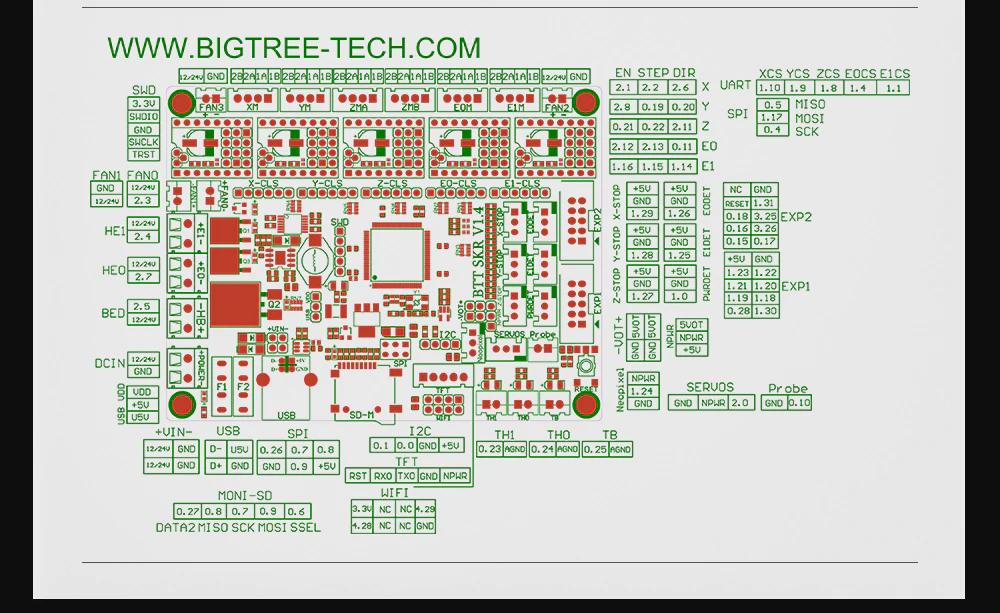
I have received the SKR v1.4 Turbo and I have 2.05 up and running.
This board has a port for an ESP and also has hardware SPI pins available for use. Pinout attached
I have created a config file for it and I have submitted it via github.
Are you willing to share the information about the wifi board you have been working on for the ReArm so I can look at getting it working on the SKR?
It would be great if we could work to getting software SPI config of the drivers working as well.
PM me if you're interested in seeing what can be done to get this going.
Edited 1 time(s). Last edit at 01/02/2020 07:05AM by jay_s.
Based in Darlington, North East
|
Re: LPC port of RepRapFirmware January 03, 2020 04:33AM |
Registered: 4 years ago Posts: 213 |
@sdavi, @jay_s
I am also very interested in getting the WiFi/esp8266 boards working with SKR hardware (I have and SKR V1.1, SKR V1.3 and have an SKR V1.4 on order).
I've worked on the LPC176x port of Marlin (added flash eeprom emulation, improved the USBMSD/USBCDC support and implemented software serial, for TMC devices). So far I've managed to build the V3 version of the firmware (though have not yet tested it) and am currently working on understanding how the code all hangs together. I've not worked with ESP8266 devices before so would be interested to hear of anyone that has gone through the process of getting the WiFiSocketServer firmware built and installed on a device (I've got a few boards on order, but there are a lot to choose from so I'e be interested to hear what hardware you would recommend).
I'm sure I will have some questions, but in general I like to work through things and understand the code as much as possible, hopefully will not be too much of a pain!
Thanks for any help you can provide.
PS I'm gloomyandy over on github as well as here.
|
Re: LPC port of RepRapFirmware January 03, 2020 05:30AM |
Registered: 10 years ago Posts: 341 |
Quote
jay_s
@sdavi
I have received the SKR v1.4 Turbo and I have 2.05 up and running.
This board has a port for an ESP and also has hardware SPI pins available for use. Pinout attached
I have created a config file for it and I have submitted it via github.
Are you willing to share the information about the wifi board you have been working on for the ReArm so I can look at getting it working on the SKR?
It would be great if we could work to getting software SPI config of the drivers working as well.
PM me if you're interested in seeing what can be done to get this going.
The WIFI adapter I made to attach to the smoothieboard is based off the wifi schematic of the Duet Wifi. It uses the ESP8266 connected to SSP0 on the lpc and requires 3 extra GPIO pins - the ported ESP wifi for LPC is currently implemented only in RRF3. I'm not sure if the WIFI firmware updater over UART works yet, haven't looked into it since i just programmed it with USB->UART chip i have here so I haven't really tried it yet. There is an extra option to compile esp wifi in the makefile. New board.txt options for the wifi is listed here: [github.com]
|
Re: LPC port of RepRapFirmware January 03, 2020 05:55AM |
Registered: 10 years ago Posts: 341 |
Quote
gloomyandy
@sdavi, @jay_s
I am also very interested in getting the WiFi/esp8266 boards working with SKR hardware (I have and SKR V1.1, SKR V1.3 and have an SKR V1.4 on order).
I've worked on the LPC176x port of Marlin (added flash eeprom emulation, improved the USBMSD/USBCDC support and implemented software serial, for TMC devices). So far I've managed to build the V3 version of the firmware (though have not yet tested it) and am currently working on understanding how the code all hangs together. I've not worked with ESP8266 devices before so would be interested to hear of anyone that has gone through the process of getting the WiFiSocketServer firmware built and installed on a device (I've got a few boards on order, but there are a lot to choose from so I'e be interested to hear what hardware you would recommend).
I'm sure I will have some questions, but in general I like to work through things and understand the code as much as possible, hopefully will not be too much of a pain!
Thanks for any help you can provide.
PS I'm gloomyandy over on github as well as here.
I followed the instructions DC42 provided on the github page of the DuetWifiSocketServer. The only issue I found was when I installed the latest version of esp8266 in arduino which had problems compiling the socketserver, installing the older 2.4 version was then successful. There is a forked version DuetWifiSocketServer also in my github which is what i use with the LPC RRF3 port. It's configured to run at 6MHz SPI with 2 max connections. I made my own board (posted in this thread not long ago) which uses the ESP-12F WiFi Module.
|
Re: LPC port of RepRapFirmware January 03, 2020 07:18AM |
Registered: 4 years ago Posts: 213 |
Quote
sdavi
I followed the instructions DC42 provided on the github page of the DuetWifiSocketServer. The only issue I found was when I installed the latest version of esp8266 in arduino which had problems compiling the socketserver, installing the older 2.4 version was then successful. There is a forked version DuetWifiSocketServer also in my github which is what i use with the LPC RRF3 port. It's configured to run at 6MHz SPI with 2 max connections. I made my own board (posted in this thread not long ago) which uses the ESP-12F WiFi Module.
Thanks for the update. I've been looking at the schematics and it looks reasonably simple to hook things up (famous last words). A few more idiotic questions if you don't mind...
1. What IDE are you using? I managed to get RRF3 built on Linux (see below for a little feedback), using vscode and the command line. Looks like you are using the Arduino IDE for the ESP-12F is that correct?
2. With the WiFi module running what can you do? Are you able to run the DuetWebControl interface? If so what is the process for running this? Do the DuetWebControl files need to be on the SD card on main board? (I said these may be idiotic).
Feedback on building RRF 3 on Linux....
1. Directory layout. I struggled a bit with this at first but eventually ended up checking out CoreLPC4RRF and then checking out RepRapFirmware, RRFLibraries and DuetWiFiSocketServer into the top level CoreLPC4RRF dir as this seems to match the layout expected by the makefile.
2. I hit a few issues with case sensitivity of some filenames (WiFi v WIFI etc), but these are easily fixed.
3. One thing that is a little strange is that I have the V3-dev branch for CoreLPC4RRF, v3-dev-lpc branch for RepRapFirmware, but for both RRFLibraries and DuetWiFiSocketServer I have to have the master branch checked out. In particular if I checkout the v3-dev of RRFLibraries (as you might expect) instead of master then I get compilation errors (missing ReadLockedPointer and others). Not totally sure what is going on there, does this make any sense? Perhaps the v3-dev branch needs to be updated to match the most recent other code?
Thanks for all of your efforts on this!
|
Re: LPC port of RepRapFirmware January 03, 2020 08:26AM |
Registered: 10 years ago Posts: 341 |
Quote
gloomyandy
Thanks for the update. I've been looking at the schematics and it looks reasonably simple to hook things up (famous last words). A few more idiotic questions if you don't mind...
1. What IDE are you using? I managed to get RRF3 built on Linux (see below for a little feedback), using vscode and the command line. Looks like you are using the Arduino IDE for the ESP-12F is that correct?
2. With the WiFi module running what can you do? Are you able to run the DuetWebControl interface? If so what is the process for running this? Do the DuetWebControl files need to be on the SD card on main board? (I said these may be idiotic).
Feedback on building RRF 3 on Linux....
1. Directory layout. I struggled a bit with this at first but eventually ended up checking out CoreLPC4RRF and then checking out RepRapFirmware, RRFLibraries and DuetWiFiSocketServer into the top level CoreLPC4RRF dir as this seems to match the layout expected by the makefile.
2. I hit a few issues with case sensitivity of some filenames (WiFi v WIFI etc), but these are easily fixed.
3. One thing that is a little strange is that I have the V3-dev branch for CoreLPC4RRF, v3-dev-lpc branch for RepRapFirmware, but for both RRFLibraries and DuetWiFiSocketServer I have to have the master branch checked out. In particular if I checkout the v3-dev of RRFLibraries (as you might expect) instead of master then I get compilation errors (missing ReadLockedPointer and others). Not totally sure what is going on there, does this make any sense? Perhaps the v3-dev branch needs to be updated to match the most recent other code?
Thanks for all of your efforts on this!
I use command line for compiling etc and just xcode for editing the files.
For the DuetWifiSocketServer I only installed esp8266 in ardunio to get the toolchain etc to compile it then used eclipse and updated the gcc paths etc as per the instructions.
Yes you just place the DWC files on the internal SDCard:/www/ and they will be loaded when connecting with the wifi.
Master is the one to be using for RRFLibraries and the DuetWifiSocketServer. I've now deleted that old v3 branch to avoid confusion.
Ah yes, I've now fixed the case for WIFI in the makefile on my local version and will be in the next commit.
|
Re: LPC port of RepRapFirmware January 07, 2020 04:57PM |
Registered: 4 years ago Posts: 213 |
Hi,
quick update. I've been able to build both the main firmware (using vscode and the command line) and he esp8266 firmware (using eclipse - which reminded how much I dislike eclipse!). As recommended above I used an older version of the esp development kit 2.4. After a little bit of a struggle I managed to flash the firmware to the esp8266 module I've got (I had to get a more up to date esptool to get that to work).
I then did some basic tests on the SKR board with the firmware I'd built. Basic things seem to work, I can talk to the board via USB. But I need to spend some time configuring fans/heaters etc. and I've not tested any of the motion side of things.
I then hooked the two boards together (using the SPI port that would normally talk to the external SD card and which on the SKR V1.4 is exposed via the EXP2 port). I basically followed the Duet wiring adding resistors etc. as needed. I then fired things up and used M587 and M552 and to my delight the board connected to my access point with no issues. I can now run the DuetWebControl interface and this all seems to work. I did get an error on the initial load (network error) and I see in the debug output from the esp8266 that it is refusing connections from time to time (caused by the 2 socket limit?). I've uploaded gcode (upload speed about 100K is that to be expected?). I'm really pleased with the progress so far, I need to get more of the board configured to be able to test things a little more, but right now I'm off to make a cup of tea to celebrate!
Andy
|
Re: LPC port of RepRapFirmware January 07, 2020 05:59PM |
Registered: 6 years ago Posts: 110 |
|
Re: LPC port of RepRapFirmware January 08, 2020 03:28AM |
Registered: 10 years ago Posts: 341 |
Quote
gloomyandy
Hi,
quick update. I've been able to build both the main firmware (using vscode and the command line) and he esp8266 firmware (using eclipse - which reminded how much I dislike eclipse!). As recommended above I used an older version of the esp development kit 2.4. After a little bit of a struggle I managed to flash the firmware to the esp8266 module I've got (I had to get a more up to date esptool to get that to work).
I then did some basic tests on the SKR board with the firmware I'd built. Basic things seem to work, I can talk to the board via USB. But I need to spend some time configuring fans/heaters etc. and I've not tested any of the motion side of things.
I then hooked the two boards together (using the SPI port that would normally talk to the external SD card and which on the SKR V1.4 is exposed via the EXP2 port). I basically followed the Duet wiring adding resistors etc. as needed. I then fired things up and used M587 and M552 and to my delight the board connected to my access point with no issues. I can now run the DuetWebControl interface and this all seems to work. I did get an error on the initial load (network error) and I see in the debug output from the esp8266 that it is refusing connections from time to time (caused by the 2 socket limit?). I've uploaded gcode (upload speed about 100K is that to be expected?). I'm really pleased with the progress so far, I need to get more of the board configured to be able to test things a little more, but right now I'm off to make a cup of tea to celebrate!
Andy
Yeah 2 HTTP responders is all we can fit into memory so I also changed the number of sockets to match (we also have a reduced number of open files as well to save memory). I would guess most of those refused connections are from the initial load when the browser is trying to parallel load the resources for DWC.
I just uploaded couple of 30M files as a test and they uploaded with average speeds of 208K/s and 201K/s.
Do take care with the heaters in RRF3, it hasn't had a lot of testing on the LPC port (I have only done a few test prints with beta rrf3). I rewrote the PWM side of things so it could be configurable with the new RRF3 configuration. I run the LPC port on my CNC (so no testing of PWM), and there was no interest last time I posted RRF3 beta binaries so I haven't checked it for a while (which is why there are no binary releases).
Edited 1 time(s). Last edit at 01/08/2020 03:39AM by sdavi.
|
Re: LPC port of RepRapFirmware January 08, 2020 05:37AM |
Registered: 10 years ago Posts: 14,672 |
Quote
gloomyandy
I've uploaded gcode (upload speed about 100K is that to be expected?).
Upload speed depends on several factors:
- The speed of the SD card interface. Duets use a 4-bit parallel interface to the SD card running at between 15 and 25MHz clock rate depending on the board. Every other production board that I know of uses SPI, which is much slower.
- The SPI speed between the processor and the ESP8266. Duets use 26.7MHz, which is the highest value that divides 80MHz that we could get to work reliably (without DMA overruns) on the SAM4E processor.
- The strength of the WiFi signal
- The SD card speed. Only relevant if the other factors allow a good speed.
- The buffer size used to write to the card. Larger buffers give higher speeds, because SD cards are optimised for large write bursts (which is what they get in digital cameras). Unfortunately we don't have large amounts of RAM in embedded processors.
- Enabling CRC checking (supported in Duet Web Control 2.0.4) slows down transfers a little.
You can test the speed of writing to the SD card by sending M122 P104. This will help you to determine whether the SD card + interface is the bottleneck, or SPI to ESP8266 + WiFi.
FWIW on a Duet WiFi we typically get 800kbytes/sec with a strong WiFi signal and no CRC checking, and M122 P104 returns speeds in the range 2 to 3 Mbytes/sec
HTH David
Edited 2 time(s). Last edit at 01/08/2020 05:42AM by dc42.
Large delta printer [miscsolutions.wordpress.com], E3D tool changer, Robotdigg SCARA printer, Crane Quad and Ormerod
Disclosure: I design Duet electronics and work on RepRapFirmware, [duet3d.com].


Sorry, only registered users may post in this forum.