RepRapFirmware 3.0 port for LPC1768/9 based boards
Posted by sdavi
|
Re: RepRapFirmware 3.0 port for LPC1768/9 based boards May 31, 2020 02:47AM |
Registered: 4 years ago Posts: 12 |
|
Re: RepRapFirmware 3.0 port for LPC1768/9 based boards May 31, 2020 03:51AM |
Registered: 4 years ago Posts: 12 |
Quote
jay_s
Ok. I believe the firmware would also have to be modified as I think the arrays for the pins only accept 5 inputs. Gloomyandy would have to confirm this.
What drivers is this designed for?
It should also work ok the SKR 1.4 as the EXP 1 and 2 ponputs are the same.
I'm a new bee to reprapfirmware, so i have some questions. Does reprapfirmware for skr support extension drivers? The output pin of wifi extension board which my firend designed is directly from lpc1768 digital io. The pin number is P1.18 to P1.23, and each output driver use 3 of them.
|
Re: RepRapFirmware 3.0 port for LPC1768/9 based boards May 31, 2020 04:00AM |
Registered: 12 years ago Posts: 224 |
Looking at the other boards that are supported, none of them use pins from port 1 of the LPC.
I know for some features, only pins on port 0 and 2 can be used.
External drivers can be used, I'm just not sure whether the pins your friend has picked can be used to driver the drivers.
@gloomyandy needs to answer this one
Based in Darlington, North East
I know for some features, only pins on port 0 and 2 can be used.
External drivers can be used, I'm just not sure whether the pins your friend has picked can be used to driver the drivers.
@gloomyandy needs to answer this one
Based in Darlington, North East
|
Re: RepRapFirmware 3.0 port for LPC1768/9 based boards May 31, 2020 04:14AM |
Registered: 4 years ago Posts: 12 |
|
Re: RepRapFirmware 3.0 port for LPC1768/9 based boards May 31, 2020 05:59AM |
Registered: 4 years ago Posts: 213 |
|
Re: RepRapFirmware 3.0 port for LPC1768/9 based boards May 31, 2020 06:20AM |
Registered: 4 years ago Posts: 12 |
WOW! I'm very excited for your reply! Is there a plan to support 7 drivers in the future?Quote
gloomyandy
I don't think there is any limitations on the pins the can be used for stepper drivers. However the current builds of RRF only support up 5 drivers, so if you want to use more you will need to modify the firmware and rebuild it
|
Re: RepRapFirmware 3.0 port for LPC1768/9 based boards May 31, 2020 06:29AM |
Registered: 4 years ago Posts: 12 |
|
Re: RepRapFirmware 3.0 port for LPC1768/9 based boards May 31, 2020 02:44PM |
Registered: 4 years ago Posts: 5 |
Hello together,
I've just joined the club with RRF 3.1.1-6 running on the SKR 1.3 and 5x TMC2209 connected to Raspberry Pi 4. All the info here about HW config is pretty straightforward but there is always a but and that is for me the firmware settings.
My printer is delta kossel powered by 24V 20A power supply with 240 mm heatbed and single v6 extruder. There are 3 temperature sensors:
I believe that I have all the temperature sensors configured properly but there is something fishy in assigning the sensors to the corresponding heating element. I mainly struggl with the logic how to assign temperature sensor to the heating element and how to configure temperature sensor without heating element. Another issue is how to display the sensor values in web interface.
board.txt
config.g
I've just joined the club with RRF 3.1.1-6 running on the SKR 1.3 and 5x TMC2209 connected to Raspberry Pi 4. All the info here about HW config is pretty straightforward but there is always a but and that is for me the firmware settings.
My printer is delta kossel powered by 24V 20A power supply with 240 mm heatbed and single v6 extruder. There are 3 temperature sensors:
- Semiter 104GT as heatbed sensor connected to TB pin
- PT1000 with 1k resistor connected to TH0 pin
- Semiter 104GT as an ambient sensor connected to TH1 pin
- Anycubic heat Bed soldered as 24V one
- Extruder powered by 50W 24V heating element
I believe that I have all the temperature sensors configured properly but there is something fishy in assigning the sensors to the corresponding heating element. I mainly struggl with the logic how to assign temperature sensor to the heating element and how to configure temperature sensor without heating element. Another issue is how to display the sensor values in web interface.
board.txt
Quote
//Note: Each line should be less than 120 characters.
// : Unwanted options can be commented out or set to NoPin. Lines commented out will get default values
// : for pins the default is NoPin.
// : Values for Arrays need to be contained within { and }
// : Comments can be defined with // or # (comments are not supported inside arrays)
// : Each config entry must be all on a single line.
// board definition
lpc.board = biquskr_1.3; // SKR v1.3
// ADC settings
adc.prefilter.enable = true;
adc.preFilter.numberSamples = 8;
adc.preFilter.sampleRate = 10000; //Hz
// stepper pins
stepper.TmcUartPin = {1.17, 1.15, 1.10, 1.8, 1.1}; // XCS, YCS, ZCS, E0CS, E1CS
stepper.numSmartDrivers = 5; // 5x TMC2209
// SBC pins
sbc.lpcTfrReadyPin = 1.31;
// LED blinks to indicate Platform is spinning or other diagnostic
// Comment out or set to NoPin if not wanted.
leds.diagnostic = 1.18;
// Bed E0 E1
heat.tempSensePins = {0.23, 0.24, 0.25}; //tb, th0, th1
config.g
Quote
; Configuration file for SKR v1.3 (firmware version 3)
; executed by the firmware on start-up
;
; generated by RepRapFirmware Configuration Tool v2.1.4 on Sun May 31 2020 09:53:42 GMT+0200 (Central European Summer Time)
; General preferences
G90 ; send absolute coordinates...
M83 ; ...but relative extruder moves
M550 P"Kossel" ; set printer name
M665 R120 L264 B115 H250 ; Set delta radius, diagonal rod length, printable radius and homed height
M666 X0 Y0 Z0 ; put your endstop adjustments here, or let auto calibration find them
; Drives
M569 P0 S1 T0.1:0.1:0.02:0.02 ; physical drive 0 goes forwards using TMC220x driver timings
M569 P1 S1 T0.1:0.1:0.02:0.02 ; physical drive 1 goes forwards using TMC220x driver timings
M569 P2 S1 T0.1:0.1:0.02:0.02 ; physical drive 2 goes forwards using TMC220x driver timings
M569 P3 S1 T0.1:0.1:0.02:0.02 ; physical drive 3 goes forwards using TMC220x driver timings
M584 X0 Y1 Z2 E3 ; set drive mapping
M92 X80.00 Y80.00 Z80.00 E137.00 ; set steps per mm
M566 X1200.00 Y1200.00 Z1200.00 E1200.00 ; set maximum instantaneous speed changes (mm/min)
M203 X18000.00 Y18000.00 Z18000.00 E1200.00 ; set maximum speeds (mm/min)
M201 X1000.00 Y1000.00 Z1000.00 E1000.00 ; set accelerations (mm/s^2)
M906 X850 Y850 Z850 E900 I30 ; set motor currents (mA) and motor idle factor in per cent
M84 S30 ; Set idle timeout
; Axis Limits
M208 Z0 S1 ; set minimum Z
; Endstops
M574 X2 S1 P"xstopmax" ; configure active-high endstop for high end on X via pin xstopmax
M574 Y2 S1 P"ystopmax" ; configure active-high endstop for high end on Y via pin ystopmax
M574 Z2 S1 P"zstopmax" ; configure active-high endstop for high end on Z via pin zstopmax
; Z-Probe
M558 P0 H5 F120 T6000 ; disable Z probe but set dive height, probe speed and travel speed
M557 R115 S20 ; define mesh grid
; Heaters
M308 S0 P"TB" Y"thermistor" R4700 T100000 B4725 C7.06e-8 ; configure sensor 0 as thermistor on pin TB
M950 H0 C"HBED" T0 ; create bed heater output on heatbed and map it to sensor 0
M143 H0 S100 ; set temperature limit for heater 0 to 100C
M307 H0 B0 S0.70 ; disable bang-bang mode for the nozzle heater and set PWM limit
M308 S1 P"TH0" Y"pt1000" R1000 ; configure sensor 1 as PT1000 on pin TH0
M950 H1 C"HE0" T1 ; create nozzle heater output on e0heat and map it to sensor 1
M143 H1 S260 ; set temperature limit for heater 1 to 260C
M307 H1 B0 S1.00 ; disable bang-bang mode for the nozzle heater and set PWM limit
M308 S1 P"TH1" Y"thermistor" R4700 T100000 B4725 C7.06e-8 ; configure sensor 1 as thermistor on pin TH1
; Fans
M950 F0 C"FAN" Q500 ; create fan 0 on pin FAN and set its frequency
M950 F1 C"HE1" Q500 ; create fan 1 on pin HE1 and set its frequency
M106 P0 S0 H-1 ; set fan 0 value. Thermostatic control is turned off
M106 P1 T50 H1 ; set fan 1 value. Thermostatic control is turned on at 50°C
; Tools
M563 P0 H0 ; define tool 0 (heatbed)
M563 P1 D0 H1 F0 ; define tool 1 (extruder)
M563 P2 D1 H-1 ; define tool 2 (ambient temp)
G10 P0 X0 Y0 Z0 ; set tool 0 axis offsets
G10 P0 R0 S0 ; set initial tool 0 active and standby temperatures to 0C
; Custom settings are not defined
;T1 ; select first tool
|
Re: RepRapFirmware 3.0 port for LPC1768/9 based boards May 31, 2020 02:54PM |
Registered: 12 years ago Posts: 224 |
@jafido
You don't need to assign the bed as a tool
Add "M140 H0" after your M307 H0
For the other sensor, give it a name using an A"name" on the M380 for the sensor. Make sure you use S2 rather than S1 (as its sensor 2).
So assuming the last one is your extra sensor "M308 S2 P"TH1" Y"thermistor" A"Sensor" R4700 T100000 B4725 C7.06e-8 ; configure sensor 1 as thermistor on pin TH1"
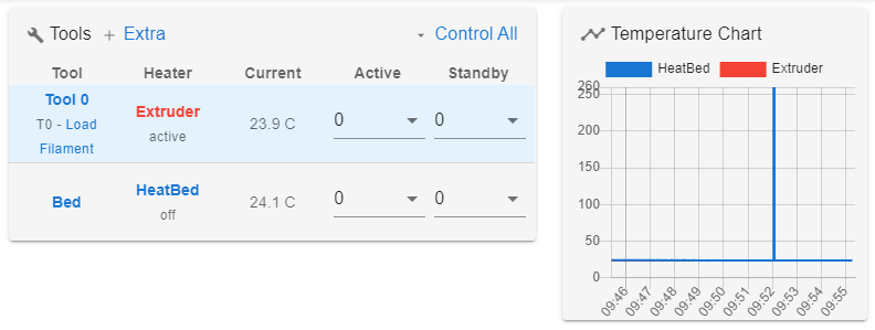
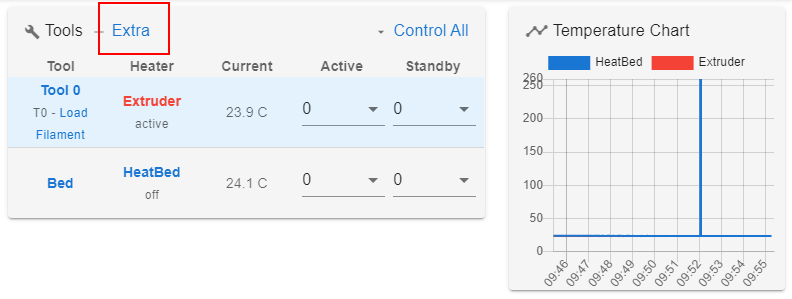
The use the "+extra" next to the tools where the temperatures are shown as you can add the sensor to the chart there.
If you want it to always be displayed, then you need to add it to a dummy tool [forum.duet3d.com]
You also said you have 5 TMC209 but you've only mapped 4 of them. Whats the other one for?
Edited 1 time(s). Last edit at 05/31/2020 02:55PM by jay_s.
Based in Darlington, North East
You don't need to assign the bed as a tool
Add "M140 H0" after your M307 H0
For the other sensor, give it a name using an A"name" on the M380 for the sensor. Make sure you use S2 rather than S1 (as its sensor 2).
So assuming the last one is your extra sensor "M308 S2 P"TH1" Y"thermistor" A"Sensor" R4700 T100000 B4725 C7.06e-8 ; configure sensor 1 as thermistor on pin TH1"
The use the "+extra" next to the tools where the temperatures are shown as you can add the sensor to the chart there.
If you want it to always be displayed, then you need to add it to a dummy tool [forum.duet3d.com]
You also said you have 5 TMC209 but you've only mapped 4 of them. Whats the other one for?
Edited 1 time(s). Last edit at 05/31/2020 02:55PM by jay_s.
Based in Darlington, North East
|
Re: RepRapFirmware 3.0 port for LPC1768/9 based boards June 01, 2020 04:03AM |
Registered: 4 years ago Posts: 5 |
thanks jay_s,
I haven't got from description "The first example informs the firmware that bed heater 0 (implied, because no P parameter is provided) uses heater 0." that M140 H0 command does the trick . My learning curve to be familiar with the RRF is not so steep as I would expect from youtube videos.
I've modified the config.g according to your suggestions but I am still not able to display the ambient sensor.
The 5th driver is currently not used but I plan to use it as a second extruder or for the moving RPI camera
Edited 3 time(s). Last edit at 06/01/2020 07:32PM by jafido.
I haven't got from description "The first example informs the firmware that bed heater 0 (implied, because no P parameter is provided) uses heater 0." that M140 H0 command does the trick
. My learning curve to be familiar with the RRF is not so steep as I would expect from youtube videos. I've modified the config.g according to your suggestions but I am still not able to display the ambient sensor.
Quote
; Heaters
M308 S0 A"HeatBed" P"TB" Y"thermistor" R4700 T100000 B4725 C7.06e-8 ; configure sensor 0 as thermistor on pin TB
M950 H0 C"HBED" T0 ; create bed heater output on heatbed and map it to sensor 0
M307 H0 B0 S0.70 ; disable bang-bang mode for the nozzle heater and set PWM limit
M140 H0 ; map heated bed to heater 0
M143 H0 S105 ; set temperature limit for heater 0 to 105C
M308 S1 A"Extruder" P"TH0" Y"pt1000" R1000 ; configure sensor 1 as PT1000 on pin TH0
M950 H1 C"HE0" T1 ; create nozzle heater output on e0heat and map it to sensor 1
M143 H1 S260 ; set temperature limit for heater 1 to 260C
M307 H1 B0 S1.00 ; disable bang-bang mode for the nozzle heater and set PWM limit
M308 S2 A"Ambient" P"TH1" Y"thermistor" R4700 T100000 B4725 C7.06e-8; configure sensor 2 as thermistor on pin TH1
; Tools
M563 P0 D0 H1 F0 ; define tool 1 (extruder)
G10 P0 X0 Y0 Z0 ; set tool 0 axis offsets
G10 P0 R0 S0 ; set initial tool 0 active and standby temperatures to 0C
; Custom settings are not defined
T0 ; select first tool
The 5th driver is currently not used but I plan to use it as a second extruder or for the moving RPI camera
Edited 3 time(s). Last edit at 06/01/2020 07:32PM by jafido.
|
Re: RepRapFirmware 3.0 port for LPC1768/9 based boards June 01, 2020 04:06AM |
Registered: 12 years ago Posts: 224 |
|
Re: RepRapFirmware 3.0 port for LPC1768/9 based boards June 01, 2020 08:45AM |
Registered: 12 years ago Posts: 224 |
|
Re: RepRapFirmware 3.0 port for LPC1768/9 based boards June 01, 2020 07:24PM |
Registered: 4 years ago Posts: 5 |
thanks again Jay_s,
there was nothing but after few restarts the change was propagated. . This firmware is like from another world. It is completely different philosophy in comparison to the Marlin. Is there any chance that somebody has already designed the PCB for SBC and SKR v1.3/1.4? I wanna build some and it is a question whether to design it from the scratch or somebody has already made it.
there was nothing but after few restarts the change was propagated.
. This firmware is like from another world. It is completely different philosophy in comparison to the Marlin. Is there any chance that somebody has already designed the PCB for SBC and SKR v1.3/1.4? I wanna build some and it is a question whether to design it from the scratch or somebody has already made it.
|
Re: RepRapFirmware 3.0 port for LPC1768/9 based boards June 02, 2020 12:54AM |
Registered: 12 years ago Posts: 224 |
[www.tindie.com]
User PCR sells boards for the wifi add on and SBC add on
Based in Darlington, North East
User PCR sells boards for the wifi add on and SBC add on
Based in Darlington, North East
|
Re: RepRapFirmware 3.0 port for LPC1768/9 based boards June 02, 2020 04:07AM |
Registered: 8 years ago Posts: 14 |
Good day. Tell me about this error.
>>> M552 S0
SENDING:M552 S0
WiFi module started
Error: Failed to initialise WiFi module, code -7
[ERROR] Error: Failed to initialise WiFi module, code -7
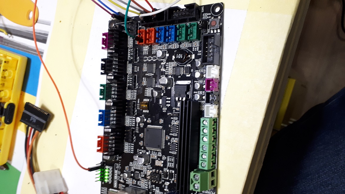
MKS Sbase v1.3
I did everything just like here [github.com]
>>> M552 S0
SENDING:M552 S0
WiFi module started
Error: Failed to initialise WiFi module, code -7
[ERROR] Error: Failed to initialise WiFi module, code -7
MKS Sbase v1.3
I did everything just like here [github.com]
|
Re: RepRapFirmware 3.0 port for LPC1768/9 based boards June 02, 2020 04:21AM |
Registered: 4 years ago Posts: 213 |
@kasper that error means that rrf is unable to talk to the esp8266 module. There are many possible reasons for this....
1. Wrong sort of WiFi module, or firmware not installed.
2. Wiring problems between the boards
3. Poor power supply to the module
4. Problems with the modification to the Sbase board
5. Probably a few others as well
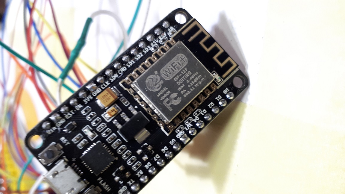
It would probably help if you posted pictures of your WiFi module and close up pictures of the wiring to the module and the wiring on the board, please also include close ups of the modifications to the SBase board.
1. Wrong sort of WiFi module, or firmware not installed.
2. Wiring problems between the boards
3. Poor power supply to the module
4. Problems with the modification to the Sbase board
5. Probably a few others as well
It would probably help if you posted pictures of your WiFi module and close up pictures of the wiring to the module and the wiring on the board, please also include close ups of the modifications to the SBase board.
|
Re: RepRapFirmware 3.0 port for LPC1768/9 based boards June 02, 2020 04:40AM |
Registered: 8 years ago Posts: 14 |
|
Re: RepRapFirmware 3.0 port for LPC1768/9 based boards June 02, 2020 04:43AM |
Registered: 12 years ago Posts: 224 |
|
Re: RepRapFirmware 3.0 port for LPC1768/9 based boards June 02, 2020 05:06AM |
Registered: 8 years ago Posts: 14 |
Power is connected to the Vin on Wi-Fi on Sbase to the 5v pin in the EXP-1 connector
board.txt
// Board Hardware configuration file for MKS Sbase 1.3
// generated by RepRapFirmware Configuration Tool (LPC Version) v2
// on Tue Jun 02 2020 09:07:48 GMT+0300 (Москва, стандартное время)
//Note: Each line should be less than 120 characters.
// : Unwanted options can be commented out or set to NoPin. Lines commented out will get default values
// : for pins the default is NoPin.
// : Values for Arrays need to be contained within { and }
// : Comments can be defined with // or # (comments are not supported inside arrays)
// : Each config entry must be all on a single line.
//Config for MKS Sbase v1.3
lpc.board = mkssbase_v1.3
//wifi pins
8266wifi.espDataReadyPin = 2.11
8266wifi.lpcTfrReadyPin = 1.30
8266wifi.espResetPin = 1.31
adc.prefilter.enable = true
SSP0.pins = {0.15, 0.17, 1.24, 0.16}
//LED blinks to indicate Platform is spinning or other diagnostic
//Comment out or set to NoPin if not wanted.
leds.diagnostic = 1.18;
//Internal SDCard SPI Frequency.
lpc.internalSDCard.spiFrequencyHz = 25000000;
//Only supports 1 External SDCard
//externalSDCard.csPin = 0.28;
//externalSDCard.cardDetectPin = 0.27;
//lpc.externalSDCard.spiFrequencyHz = 4000000;
//lpc.externalSDCard.spiChannel = 0;
//LCD Pins (only ST9720 SPI currently supported)
//lcd.spiChannel = 0;
//lcd.lcdCSPin = 0.16;
//lcd.lcdBeepPin = 1.31;
//lcd.encoderPinA = 3.25;
//lcd.encoderPinB = 3.26;
//lcd.encoderPinSw = 1.30; //click
//lcd.lcdDCPin = NoPin; //DataControl Pin (A0) if none used set to NoPin
//lcd.panelButtonPin = 2.11; //Extra button on RRD Panel
heat.tempSensePins = {TH1, TH2}; //Max of 3 entries
//heat.spiTempSensorCSPins = { }; //Max of 2 entries
|
Re: RepRapFirmware 3.0 port for LPC1768/9 based boards June 02, 2020 05:12AM |
Registered: 12 years ago Posts: 224 |
It could be that board.txt is being loaded as the values here
You only really need
in your board.txt file.
Can you change that and then send M122 and M122 P200 and verify that the SSP0 changes are in effect and that the board is being reported correctly
Based in Darlington, North East
heat.tempSensePins = {TH1, TH2}; //Max of 3 entries
are not valid.You only really need
//Config for MKS Sbase v1.3
lpc.board = mkssbase_v1.3
//wifi pins
8266wifi.espDataReadyPin = 2.11
8266wifi.lpcTfrReadyPin = 1.30
8266wifi.espResetPin = 1.31
adc.prefilter.enable = true
SSP0.pins = {0.15, 0.17, 1.24, 0.16}
in your board.txt file.
Can you change that and then send M122 and M122 P200 and verify that the SSP0 changes are in effect and that the board is being reported correctly
Based in Darlington, North East
|
Re: RepRapFirmware 3.0 port for LPC1768/9 based boards June 02, 2020 05:26AM |
Registered: 8 years ago Posts: 14 |
SENDING:M122 P200
== Configurable Board.txt Settings ==
lpc.board = generic
leds.diagnostic = 1.18
stepper.enablePins = { NoPin NoPin NoPin NoPin NoPin }
stepper.stepPins = { NoPin NoPin NoPin NoPin NoPin }
stepper.directionPins = { NoPin NoPin NoPin NoPin NoPin }
stepper.digipotFactor = 0.00
stepper.TmcUartPins = { NoPin NoPin NoPin NoPin NoPin }
stepper.numSmartDrivers = 0
heat.tempSensePins = { NoPin NoPin NoPin NoPin }
heat.spiTempSensorCSPins = { NoPin NoPin }
heat.spiTempSensorChannel = 0
atx.powerPin = NoPin
atx.powerPinInverted = false
sdCard.internal.spiFrequencyHz = 25000000
sdCard.external.csPin = NoPin
sdCard.external.cardDetectPin = NoPin
sdCard.external.spiFrequencyHz = 4000000
sdCard.external.spiChannel = 255
softwareSPI.pins = { NoPin NoPin NoPin }
SSP0.pins = { 0.15 0.17 1.24 0.16 }
8266wifi.espDataReadyPin = 2.11
8266wifi.lpcTfrReadyPin = 1.30
8266wifi.espResetPin = 1.31
8266wifi.serialRxTxPins = { NoPin NoPin }
serial.aux.rxTxPins = { 0.3 0.2 }
adc.prefilter.enable = true
adc.preFilter.numberSamples = 8
adc.preFilter.sampleRate = 10000
== Hardware Serial ==
AUX Serial: UART 0
WIFI Serial: Disabled
== Software PWM ==
== Servo PWM ==
Hardware PWM = 50Hz [ NoPin NoPin NoPin NoPin NoPin NoPin ]
Timer2 PWM = 50Hz [ NoPin NoPin NoPin ]
it just happened. Probably another mistake somewhere.
|
Re: RepRapFirmware 3.0 port for LPC1768/9 based boards June 02, 2020 05:40AM |
Registered: 12 years ago Posts: 224 |
|
Re: RepRapFirmware 3.0 port for LPC1768/9 based boards June 02, 2020 05:50AM |
Registered: 8 years ago Posts: 14 |
|
Re: RepRapFirmware 3.0 port for LPC1768/9 based boards June 02, 2020 06:08AM |
Registered: 4 years ago Posts: 213 |
Something strange going off here. It has picked up some of the board.txt settings (look at the SSP0.Pins values for instance), but it does not seem to have picked up the board type correctly. @kasper I would check very carefully that there are no odd characters around the line that contains "lpc.board = mkssbase_v1.3", I'd be tempted to delete that line and re-enter it.
|
Re: RepRapFirmware 3.0 port for LPC1768/9 based boards June 02, 2020 06:31AM |
Registered: 12 years ago Posts: 224 |
|
Re: RepRapFirmware 3.0 port for LPC1768/9 based boards June 02, 2020 06:41AM |
Registered: 8 years ago Posts: 14 |
|
Re: RepRapFirmware 3.0 port for LPC1768/9 based boards June 02, 2020 06:57AM |
Registered: 12 years ago Posts: 224 |
Maybe you could try reflashing the ESP software based on PCR's instructions
[rosspeter.org]
Based in Darlington, North East
[rosspeter.org]
Based in Darlington, North East
|
Re: RepRapFirmware 3.0 port for LPC1768/9 based boards June 02, 2020 07:08AM |
Registered: 8 years ago Posts: 14 |
Quote
jay_s
Maybe you could try reflashing the ESP software based on PCR's instructions
[rosspeter.org]
Yes I've tried it once or twice )
|
Re: RepRapFirmware 3.0 port for LPC1768/9 based boards June 02, 2020 08:15AM |
Registered: 4 years ago Posts: 213 |
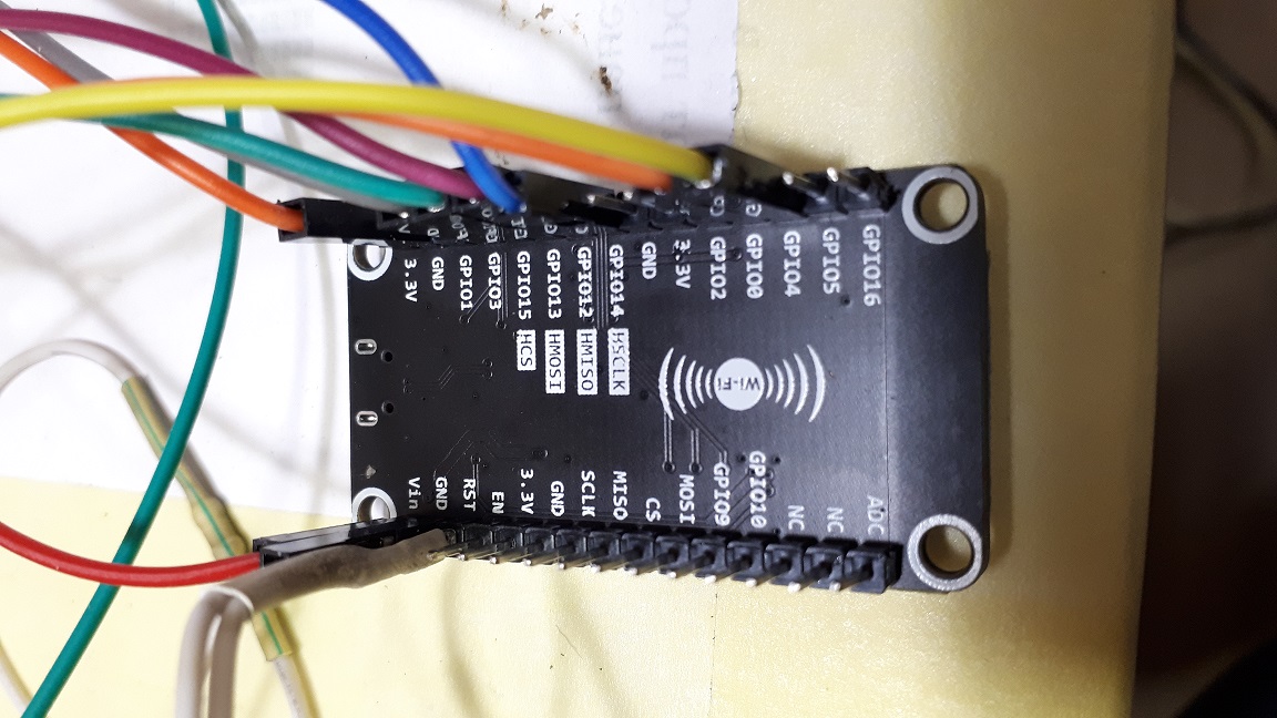
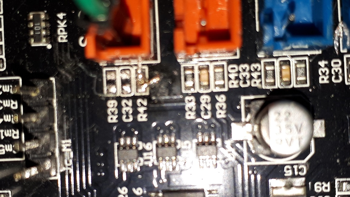
It looks to me like you are connecting to at least one of P0_15, P0_16, P0_17 via the pins in EXP1, don't do this, use the pins on J7 (you are already doing this for two of the pins, but I can't tell from the photos which ones), you basically want all three of those connections to go to J7.
If you are still having problems please take some more pictures that show the connections to J7 and EXP1 more clearly and do the same for the ESP board. At the moment I can't really check what you have connected.
If you are still having problems please take some more pictures that show the connections to J7 and EXP1 more clearly and do the same for the ESP board. At the moment I can't really check what you have connected.
|
Re: RepRapFirmware 3.0 port for LPC1768/9 based boards June 02, 2020 09:17AM |
Registered: 8 years ago Posts: 14 |
Quote
gloomyandy
It looks to me like you are connecting to at least one of P0_15, P0_16, P0_17 via the pins in EXP1, don't do this, use the pins on J7 (you are already doing this for two of the pins, but I can't tell from the photos which ones), you basically want all three of those connections to go to J7.
If you are still having problems please take some more pictures that show the connections to J7 and EXP1 more clearly and do the same for the ESP board. At the moment I can't really check what you have connected.
thank you very much. And exactly, was P0. 16 connected to EXP-1
now it shows like this
>>> M552
SENDING:M552
WiFi module is idle
can you tell me how to find out the IP address?


Sorry, only registered users may post in this forum.