Introducing the Prism Mendel
Posted by Buback
|
Re: Introducing the Prism Mendel February 24, 2012 10:33AM |
Registered: 13 years ago Posts: 601 |
there are a couple issues with that approach (not insurmountable).
First, the distance between the smooth/threaded rod is 30mm. If you change this, you can't use any of the existing (or future) x ends without modification.
second, if you keep the distance 30mm, you have to move the position of the threaded rod as well. since the extrusion is 20mm itself, there's no way to fit a 608 bearing in, unless you move it up above the extrusion. attaching the idler gear might still be tricky, if there isn't enough clearance for m8 bolts. it would also reduce potential z travel.
it would also make any x end stick out even further than it does now, which is something that I didn't want to do with this remodel.
Anyway, The main issue is the ztop piece. You would be able to just add the rods in anytime if you could get a tool into the screws when the rod is installed.
Re-designing that one piece would make assembly much easier. I'll put a couple different options up in the coming weeks for consideration.
Also, after duexvis or someone else makes one and can provide a critical eye, I'll feel more comfortable pushing the design in other parts of the forum and around the reprap world.
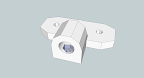
edit i've attached ( ) one idea for a new z top. it combines a leadscrew end constraint (w/ 608 bearing) with the rod holder. it would attach to the inside of the frame triangle, and has slots instead of holes. This is just an idea, for now.
Edited 1 time(s). Last edit at 02/24/2012 11:32AM by Buback.
First, the distance between the smooth/threaded rod is 30mm. If you change this, you can't use any of the existing (or future) x ends without modification.
second, if you keep the distance 30mm, you have to move the position of the threaded rod as well. since the extrusion is 20mm itself, there's no way to fit a 608 bearing in, unless you move it up above the extrusion. attaching the idler gear might still be tricky, if there isn't enough clearance for m8 bolts. it would also reduce potential z travel.
it would also make any x end stick out even further than it does now, which is something that I didn't want to do with this remodel.
Anyway, The main issue is the ztop piece. You would be able to just add the rods in anytime if you could get a tool into the screws when the rod is installed.
Re-designing that one piece would make assembly much easier. I'll put a couple different options up in the coming weeks for consideration.
Also, after duexvis or someone else makes one and can provide a critical eye, I'll feel more comfortable pushing the design in other parts of the forum and around the reprap world.
edit i've attached ( ) one idea for a new z top. it combines a leadscrew end constraint (w/ 608 bearing) with the rod holder. it would attach to the inside of the frame triangle, and has slots instead of holes. This is just an idea, for now.

Edited 1 time(s). Last edit at 02/24/2012 11:32AM by Buback.
|
Re: Introducing the Prism Mendel March 04, 2012 10:51AM |
Registered: 12 years ago Posts: 40 |
Thanks for the good design!
I am trying to assemble Prism as well after I assembled Prusa and found it easier to work with. Plus there is much less annoying work with cutting threaded rods
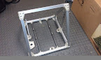
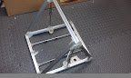
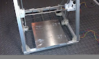
So here is my frame:
Only issue so far I do not have enough room under frame for threaded Z rod and nut touches the table. But that can be easily fixed.
I am going to print X-axis from Prusa but noticed that on my assembled Prusa distance btw threaded and smooth Z rods centers is 31mm, but here I got 30mm (I just measured in place). Do I need to modify Prusa models for X-motor and X-idler accordingly?
Slava
PS Good idea - ztop with bearing, unfortunately I already cut threaded Z too short for that ;(
Edited 2 time(s). Last edit at 03/04/2012 11:00AM by rGlory.
I am trying to assemble Prism as well after I assembled Prusa and found it easier to work with. Plus there is much less annoying work with cutting threaded rods
So here is my frame:
 |
| From Prism |
 |
| From Prism |
Only issue so far I do not have enough room under frame for threaded Z rod and nut touches the table. But that can be easily fixed.
I am going to print X-axis from Prusa but noticed that on my assembled Prusa distance btw threaded and smooth Z rods centers is 31mm, but here I got 30mm (I just measured in place). Do I need to modify Prusa models for X-motor and X-idler accordingly?
Slava
PS Good idea - ztop with bearing, unfortunately I already cut threaded Z too short for that ;(
Edited 2 time(s). Last edit at 03/04/2012 11:00AM by rGlory.
|
Re: Introducing the Prism Mendel March 04, 2012 01:00PM |
Registered: 13 years ago Posts: 601 |
That is a major issue with no clear answer. I made it 30mm because i plan on eventually using a vertical X axis as the standard for prism, and there is a working standard for that distance for vertical x axis designs. but, as far as i recall, there isn't a clear cut distance for the sells or prusa x ends.
anyway, i have greg frost prusa x ends on my prism right now and they work ok. no problem with the spacing that i notice. The biggest problem is that the motor is in the same z-y plane as the frame triangle, which severely limits my z travel since the motor hits the triangle. i think the standard prusa x motor end would alleviate this issue.
And no worries about the ztop w/bearing. I use the standard prusa z rod constraint pieces for the same effect. you don't need to use them, but it does seem to give a bit more consistency to the exterior finish.
|
Re: Introducing the Prism Mendel March 04, 2012 09:02PM |
Registered: 12 years ago Posts: 40 |
> That is a major issue with no clear answer. I made it 30mm because i plan on eventually using a vertical X axis as the standard for prism, and there is a working standard for that distance for vertical x axis designs. but, as far as i recall, there isn't a clear cut distance for the sells or prusa x ends.
Actually I just realized that I assembled X-ends on my Prusa quite incorrect which made that 1mm difference. So 30mm is correct.
> The biggest problem is that the motor is in the same z-y plane as the frame triangle, which severely limits my z travel since the motor hits the triangle. i think the standard prusa x motor end would alleviate this issue.
I am actually printing right now Adrian's x-ends for prusa: [reprap.org]
This may eliminate the issue. I will let you know as soon I try it.
Actually I just realized that I assembled X-ends on my Prusa quite incorrect which made that 1mm difference.
So 30mm is correct.> The biggest problem is that the motor is in the same z-y plane as the frame triangle, which severely limits my z travel since the motor hits the triangle. i think the standard prusa x motor end would alleviate this issue.
I am actually printing right now Adrian's x-ends for prusa: [reprap.org]
This may eliminate the issue. I will let you know as soon I try it.
|
Re: Introducing the Prism Mendel March 04, 2012 11:23PM |
Registered: 12 years ago Posts: 40 |
Hmm looking into Adrians X-end printing I came with idea what Prism X-end could be...
I think it should be more rigid and designed to use linear bearings only. Then it can use only 2 instead of 4.
I will make a SketchUp image tomorrow with this idea to see what you guys think about it...
PS My printer have finished printing Adrians x-end for Prusa. I just tried it in place and seems to work well (x motor does not iteract with frame so it can go up almost till bearing hits z-rod holder) :
Edited 3 time(s). Last edit at 03/05/2012 10:07AM by rGlory.
I think it should be more rigid and designed to use linear bearings only. Then it can use only 2 instead of 4.
I will make a SketchUp image tomorrow with this idea to see what you guys think about it...
PS My printer have finished printing Adrians x-end for Prusa. I just tried it in place and seems to work well (x motor does not iteract with frame so it can go up almost till bearing hits z-rod holder) :
 |
| From Prism |
 |
| From Drop Box |
|
Re: Introducing the Prism Mendel March 05, 2012 03:24PM |
Registered: 13 years ago Posts: 601 |
Linear bearings are a must these days, in my opinion.
I'll have to print out one of those x ends. thanks for testing!
oh and i said this:
by which i meant that the distance is ~30mm, but since it's openSCAD, the distance can change based around what parameters you choose. in other words, it's not set down on some type of schematic drawing. i don't want to start any arguments
I'll have to print out one of those x ends. thanks for testing!
oh and i said this:
Quote
buback
but, as far as i recall, there isn't a clear cut distance for the sells or prusa x ends.
by which i meant that the distance is ~30mm, but since it's openSCAD, the distance can change based around what parameters you choose. in other words, it's not set down on some type of schematic drawing. i don't want to start any arguments
|
Re: Introducing the Prism Mendel March 05, 2012 06:48PM |
Registered: 12 years ago Posts: 40 |
So here is my idea for Prism X ends:
Of course this is way too far from end design, just to show idea. So bearing bed is only for one bearing and belt is going around. That will require 2 bearings more than prusa X-ends, but what I do not like with prusa ends there is force only on one side of X-ends when belt is tensioned. With original mendel belt just pushes both ends together evenly.
Also I think it would be not a bad idea to put bridge btw linear bearings bed and nut holder on top for rigidity.
Edited 2 time(s). Last edit at 03/05/2012 06:50PM by rGlory.
|
Re: Introducing the Prism Mendel March 06, 2012 11:07AM |
Admin Registered: 12 years ago Posts: 2,569 |
Nice to see some action on the Prism, my own build has been delayed for some time.
Nice idea for the X end, but I would center the motor and use 2 bearings on each side. When a belt pulley only use a quarter of its perimeter to grip on the belt tooth, it's more likely to suffer from skip or lash. Also it would allow the belt to run its smooth side on the bearings instead of its toothed side, which could create ripples on prints otherwise.
Most of my technical comments should be correct, but is THIS one ?
Anyway, as a rule of thumb, always double check what people write.
|
Re: Introducing the Prism Mendel March 06, 2012 05:14PM |
Registered: 12 years ago Posts: 40 |
DeuxVis Wrote:
-------------------------------------------------------
> Nice idea for the X end, but I would center the motor and use 2 bearings on each side.
Back to original Mendel? I think issue with it in this case - bearings will have to be far enough behind the motor, so pulley will be properly covered by belt. That will increase size of X-end and amount of plastic.
> When a belt pulley only use a quarter of its perimeter to grip
> on the belt tooth, it's more likely to suffer from skip or lash.
Actually on that pictures, it is more that quarter as bearing center not on the line with motor. Probably motor can be moved even little more back.
> Also it would allow the belt to run
> its smooth side on the bearings instead of its
> toothed side, which could create ripples on prints
> otherwise.
Belt is already on toothed side to bearings on original Prusa X-ends, also on Y axis, so it would not be worse than that I guess.
|
Re: Introducing the Prism Mendel March 07, 2012 09:21AM |
Registered: 12 years ago Posts: 40 |
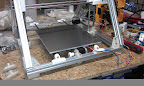
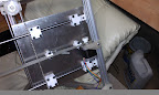
I think y-rods installed low, which will require additional sheet or to much plastic btw linear bearings and first one. I measured at least 25mm to make it go over Y motor. I modified Y-Z rod holders like this:
And it looks promising:
Aluminium sheet is not attached to y rods, just lays on top of linear bearings, proper installation will make some more room, so I think this should work.
Edited 1 time(s). Last edit at 03/07/2012 09:24AM by rGlory.
 |
| From Prism |
And it looks promising:
 |
| From Prism |
Aluminium sheet is not attached to y rods, just lays on top of linear bearings, proper installation will make some more room, so I think this should work.
Edited 1 time(s). Last edit at 03/07/2012 09:24AM by rGlory.
|
Re: Introducing the Prism Mendel March 07, 2012 11:25AM |
Registered: 13 years ago Posts: 601 |
the y motor bracket and idler are asymmetrical, so it can be flipped over to give you an extra 5mm (though this might cause some interference with the z belt). I did this so that i could eventually do a double precision belt mod.
yeah i think we'll need a dedicated prism y carriage, or at least something like the squashed frog from the original mendel. please post some designs on thingiverse! i'll do one up, too.
also, you'll probably want to turn your y motor so the wires don't stick up in the way of the y bed.
also i'll have to take a look at how i installed the z rods, ie how many washers i used and such. when i did it initally, i didn't have any problems with it hitting the table the printer is on. since i changed the x axis to prusa x ends, however, the z rod ends touch the table. so i know it can fit with some combo of washers etc. it should be very close, though, like 1--3 mm.
|
Re: Introducing the Prism Mendel March 07, 2012 12:42PM |
Registered: 12 years ago Posts: 40 |
> the y motor bracket and idler are asymmetrical, so it can be flipped over to give you an extra 5mm (though this might cause some interference with the z belt).
Yes I know, but I need at least 25mm, that would be still 20mm more.
> please post some designs on thingiverse! i'll do one up, too.
Sure: [www.thingiverse.com]
> also, you'll probably want to turn your y motor so the wires don't stick up in the way of the y bed.
Yes, I will. Thanks. I did not touch it yet as I thought how to fix this 25mm issue, and was thinking on put motor even lower. But that still not enough and it will interference with z-rod indeed.
|
Re: Introducing the Prism Mendel March 09, 2012 12:36PM |
Registered: 12 years ago Posts: 40 |
|
Re: Introducing the Prism Mendel March 13, 2012 06:53AM |
Admin Registered: 12 years ago Posts: 2,569 |
I started assembling the frame.
Man, that's so easy compared to my previous build (a Huxley with lots of tiny bearings, bolts and bits everywhere). Thanks for your work on that Design Buback
Most of my technical comments should be correct, but is THIS one ?
Anyway, as a rule of thumb, always double check what people write.
Man, that's so easy compared to my previous build (a Huxley with lots of tiny bearings, bolts and bits everywhere). Thanks for your work on that Design Buback
Most of my technical comments should be correct, but is THIS one ?
Anyway, as a rule of thumb, always double check what people write.
|
Re: Introducing the Prism Mendel March 18, 2012 04:27AM |
Registered: 12 years ago Posts: 18 |
I'm very interested in building this as well. I currently have a ToM mk7, and I had considered converting it to a Prusa. But after reading up more about Prusa and the conversion I might as well build a new one and have 2! (Or sell one) Since I'm relatively new to RepRaps in general, can you help me put together a parts list? So far your parts list is for someone with a Mendel and wish to convert. What if I'm starting from scratch? Here's my list:
1. Printed parts from your stl files.
2. All the parts you mentioned above, extruded aluminum, M3/4/8 bolts, new smooth rods etc.
3. Do I use the smooth rod from a Mendel kit for the X axis?
4. Hot end
5. 5 NEMA17 stepper motors
6. HBP, what about the bed itself that rides on the Y Axis?
7. All electronics (what's the best place with a complete kit in US?)
8. Any other nuts and bolts? Since I don't own a Mendel, I'll need all nuts/bolts and hardware
Another dumb question, am I supposed to drill into the extruded aluminum? How do I make sure everything's square? I think I found the answer to this question, I the nut will stay in the channel of the extruded aluminum.
Edited 3 time(s). Last edit at 03/18/2012 04:42AM by rcboosted.
|
Re: Introducing the Prism Mendel March 19, 2012 11:23AM |
Registered: 12 years ago Posts: 40 |
> 5. 5 NEMA17 stepper motors
You only need 4 btw
> 6. HBP, what about the bed itself that rides on the Y Axis?
I may have spare acrylic bed that should work with rods I posted here before. I am waiting ponoko for building it, they promised it will be made this Friday. But I will need to check that my design is correct first. If it is, I can share it with you.
> 7. All electronics (what's the best place with a complete kit in US?)
I ordered my RAMS at ultimachine.com they provide it full DIY, partially or fully soldered, I am not 100% sure they are the cheapest, but their service is great.
> Another dumb question, am I supposed to drill into the extruded aluminum?
No, that the point of having extruded aluminium - you move T-nuts around.
> How do I make sure everything's square?
I just aligned them the same way everywhere and I think that should make it square. But Buback may answer that better.
|
Re: Introducing the Prism Mendel March 19, 2012 01:44PM |
Registered: 13 years ago Posts: 601 |
rGlory Wrote:
-------------------------------------------------------
> > 5. 5 NEMA17 stepper motors
> You only need 4 btw
Yep, only 4 motors, but you will need a continuous t5 belt (the same as for a mendel: T5 (5mm wide, 5mm pitch) 960-1010mm long. Shorter is probably better.
> > Another dumb question, am I supposed to drill
> into the extruded aluminum?
> No, that the point of having extruded aluminium -
> you move T-nuts around.
No drilling or tapping required :-) not a dumb question because i think the mendelmax does require some drilling (at least some tapping)
> > How do I make sure everything's square?
> I just aligned them the same way everywhere and I
> think that should make it square. But Buback may
> answer that better.
If you get the extrusion cut to size when ordering, it should be 99% square just because of the simple geometry: equatorial triangles and 90 deg angles. The remaining minor frame misalignment (if any) shouldn't matter too much, as long as the axes are properly parallel and perpendicular. There are little bumps on the rod holders to you can align them properly with a tape measure. For me, there was no alignment issues w the frame. That can't be said for my old mendel, even with a lot of tinkering.
Extrusion cut by hand is a different matter, since the cuts might not be square or precise enough. then you'll have to resort to the tape measure: the frame triangles are equilateral, with 400mm sides (internal), and the base is a 400mm square (again internal sides). A perpendicular line from the middle of any of the triangle sides should intersect with the opposite vertex, and all those measurements should be equal @ ~346.4mml. And the measurements between opposite corners of the square should be equal @ ~565.7. If you have to, you can cut some jigs out of paper to speed this up.
Edited 1 time(s). Last edit at 03/19/2012 01:44PM by Buback.
|
Re: Introducing the Prism Mendel March 19, 2012 02:11PM |
Registered: 13 years ago Posts: 601 |
and your other questions:
rcboosted Wrote:
-------------------------------------------------------
> 3. Do I use the smooth rod from a Mendel kit for
> the X axis?
Smooth rods only need to be ~400mm for x and y axis, and ~330mm for the z. the standard mendel x are to long, but the z and y are ok. longer x aren't an issue except for the fact that they stick out of the "box" that is the printer area, so the printer footprint is subjectively larger. (My future vertical x will need longer x rods, though, but if your printer is printing by then, who cares? I make no claims mine will be better!) longer y or z rods wouldn't fit between the extrusion, so would have to be cut down with a hacksaw (and a file helps debur the cut edges)
best sizes are, say, 400-420mm for X, 380-90mm for Y, and 330-340 for Z
> 4. Hot end
take your pick, or build your own. too subjective a topic to explore here.
> 6. HBP, what about the bed itself that rides on
> the Y Axis?
I printed out 4 lm8uu holders and screwed them to 2 lengths of flat aluminum rod stock, and then screwed the bed to those (w springs supporting it). it's a hack, really, but i wasn't happy with my old y axis design, the OpenY. the open y will work, but caused me some wobble problems with my old mendel. sorry, but i don't have a good answerer yet :-( any suggestions, anybody?
> 7. All electronics (what's the best place with a
> complete kit in US?)
i'm not the person to ask about this. I got one of the first batches of gen6 and there's been a lot of progress since them. you only need to run 4 motors, though, so this might make selection a bit easier.
> 8. Any other nuts and bolts? Since I don't own a
> Mendel, I'll need all nuts/bolts and hardware
I've had to order extra nuts and bolts ever since building my mendel, but that's just a consequence of designing and building stuff. If you can afford it, order 100 more of (most) screws, nuts, and washers. extra bearings have come in handy at times, too. It would have saved me money in the long run (on shipping). some long m3 bolts , like 35-40mm, would probably come in handy, as they are often used in the extruder these days to hold the idler block on. it's probably a good idea to peruse the mendel BOM as a lot of those screw lengths are reused on thingiverse things.
|
Re: Introducing the Prism Mendel March 19, 2012 03:45PM |
Registered: 12 years ago Posts: 40 |
Btw I made hobber tool for my dremel, this is not directly related to Prism, but I made it to build one, so anyway: [www.thingiverse.com]
|
Re: Introducing the Prism Mendel March 19, 2012 05:37PM |
Registered: 12 years ago Posts: 18 |
Wow thanks guys for all the help! It looks like I'll have to take some time to digest all this. But from what I gathered, the Prism will be more stable due to the extruded aluminum, so the wobbling axis issues found on the Prusa are gone/fixed/improved. I just need 4 NEMA17 motors since it's Mendel design, not Prusa. I like Ultimaker's motor, it's quiet, but they don't list it on their site. I need to make the build platform myself, but I can use the rods from a Prusa, just cut them shorter. I will compile a list together and post it here, hopefully it'll help someone else who's trying to build the Prism as well.
|
Re: Introducing the Prism Mendel March 19, 2012 06:09PM |
Registered: 12 years ago Posts: 40 |
|
Re: Introducing the Prism Mendel March 19, 2012 08:53PM |
Registered: 12 years ago Posts: 18 |
rGlory,
I'm not understanding how your Y rod holder works differently than Buback's. Is looks like it fits in between the extruded aluminum frame too doesn't it? It's the same 400mm frame. also, would your bed design work with bearing supports like this? [www.thingiverse.com]
I'm not understanding how your Y rod holder works differently than Buback's. Is looks like it fits in between the extruded aluminum frame too doesn't it? It's the same 400mm frame. also, would your bed design work with bearing supports like this? [www.thingiverse.com]
|
Re: Introducing the Prism Mendel March 20, 2012 07:52AM |
Admin Registered: 12 years ago Posts: 2,569 |
|
Re: Introducing the Prism Mendel March 20, 2012 06:21PM |
Registered: 12 years ago Posts: 40 |
rcboosted Wrote:
-------------------------------------------------------
> I'm not understanding how your Y rod holder works
> differently than Buback's. Is looks like it fits
> in between the extruded aluminum frame too doesn't
> it? It's the same 400mm frame.
No, as DeuxVis already said mine rod holders on top, look into the second picture where I published rod's image.
> also, would your
> bed design work with bearing supports like this?
> [www.thingiverse.com]
Existing holes on my bed design would not match that of course (unless I am extremely lucky). So you would probably have to change that model to move holes, or drill new holes in the bed. Also with my rods and these "linear bearuings" bed would be probably too high. But you may use Buback's original Y rods with these.
Btw why would you need this complex design instead of LM8UU?
|
Re: Introducing the Prism Mendel March 20, 2012 09:57PM |
Registered: 12 years ago Posts: 18 |
|
Re: Introducing the Prism Mendel March 21, 2012 10:43AM |
Registered: 12 years ago Posts: 40 |
|
Re: Introducing the Prism Mendel March 21, 2012 11:12AM |
Registered: 13 years ago Posts: 1,780 |
|
Re: Introducing the Prism Mendel March 21, 2012 12:29PM |
Registered: 13 years ago Posts: 601 |
The print bed is pretty open as is, at least much more so than the mendel/prusa. Vertical clearance is also greater than mendel/prusa. Of course, you can easily adapt the design if you need to go even higher, but the limiting point will always be when the x axis rods hit the frame triangle, if it's a horizontal x axis. A vertical x axis will top out at the end of the z axis.
|
Re: Introducing the Prism Mendel March 21, 2012 01:00PM |
Registered: 13 years ago Posts: 1,780 |
|
Re: Introducing the Prism Mendel March 21, 2012 01:28PM |
Registered: 13 years ago Posts: 601 |
This is because the frame triangles aren't in the way of the extruder. the x carriage has no restriction along the full travel of the z axis.
The horizontal extrusion at the top of the frame triangle can get in the way a bit, but it is at the vertex of the triangles, so it's higher than on the truncated triangles of the mendel (which aren't wide enough to fit an extruder through, anyway). What gets in the way is the filament, since it is directly below the horizontal extrusion, and can only bend so far before it inhibits the filament feeding.
If you are printing something very tall, you can always attach the extrusion to the side of the frame triangle, instead of at the vertex.


Sorry, only registered users may post in this forum.