Introducing the Prism Mendel
Posted by Buback
|
Re: Introducing the Prism Mendel March 21, 2012 08:08PM |
Registered: 12 years ago Posts: 18 |
|
Re: Introducing the Prism Mendel March 22, 2012 10:45AM |
Registered: 13 years ago Posts: 601 |
I have a bit of a z wobble issue because of the eccentricity of the printed z pulleys. I also know that the m8 rods don't fit precisely in the 608 bearings, so are probably a little off center there as well.
when the pulley spins around to the longer-radius side, the tension on the z belt goes up and squeezes the two z rods together, bending up the z leadscrew support blocks.
As the pulley spins to the shorter radius side, the tension is released, and the z leadscrew blocks settle back down.
I also am using the prusa leadscrew constraint pieces at the top of the z rod, which help but don't solve this issue.
Buying machined pulleys is an option, particularly if you want the absolute best print quality, but i'd rather avoid the cost of that unless absolutely necessary.
reinforcing the z leadscrew support block will help, but i think the plastic will always loose out to the steel bands in the belt. if we stop the bending of the support block, it will just bend something else, like the motor shaft.
the best option i can think of is a spring loaded idler. I'll work on the design today and see if i can come up with a fully printed design so we don't need to source springs.
|
Re: Introducing the Prism Mendel March 22, 2012 06:14PM |
Registered: 13 years ago Posts: 1,780 |
|
Re: Introducing the Prism Mendel March 23, 2012 12:41AM |
Registered: 12 years ago Posts: 18 |
Buback,
What should the belt length be? do they need to be continuous? You mentioned the Z belt needs to be, but I'm not sure about X and Y, I'm guessing it doesn't, and since the frame is 400mm, it should be around 800mm for both x and y?
I flew RC helicopters, so I HAD lots of belts that threw out recently, if only I knew I could use it in a RepRap.
How long should the threaded rod for Z be? Simple math tells me 346mm, but I doubt it needs to reach the top all the way. Scouring various site I came up with around 300mm. I'm having a really tough time coming up with a BoM since I don't own a Mendel or a Prusa. The parts list are all over the place.
Also, is everyone printing the plastic parts out of PLA for its rigidity? I printed about 1/2 of the parts in ABS already, I don't really want to reprint!
Edited 3 time(s). Last edit at 03/23/2012 06:01AM by rcboosted.
|
Re: Introducing the Prism Mendel March 23, 2012 09:06AM |
Admin Registered: 12 years ago Posts: 2,569 |
rcboosted Wrote:
-------------------------------------------------------
> What should the belt length be? do they need to
> be continuous? You mentioned the Z belt needs to
> be, but I'm not sure about X and Y, I'm guessing
> it doesn't, and since the frame is 400mm, it
> should be around 800mm for both x and y?
Yes, Z closed, the others opened. You can use a regular Mendel belt set. 800 mm will be a bit short for the Z.
> How long should the threaded rod for Z be? Simple
> math tells me 346mm, but I doubt it needs to reach
> the top all the way. Scouring various site I came
> up with around 300mm.
The Prism wiki says 300 to 340 mm. I cut mine to 330, will see how that fits.
> Also, is everyone printing the plastic parts out
> of PLA for its rigidity? I printed about 1/2 of
> the parts in ABS already, I don't really want to
> reprint!
Yes we do, although everything near to the heated bed / hotend maybe better in ABS for temperature resistance reasons.
I believe you can continue doing it all in ABS, all the Prism parts that need to be rigid are quite massive so that should work.
Maybe the Y axis idler and motor supports are better if they can't flex then. I did a second Y belt idler support (mirrored) and will mount both together so I'm sure the idler wont move, and that's PLA.
Most of my technical comments should be correct, but is THIS one ?
Anyway, as a rule of thumb, always double check what people write.
|
Re: Introducing the Prism Mendel March 23, 2012 10:20AM |
Registered: 13 years ago Posts: 601 |
Yeah i added a mirored y belt idler as well. just having one worked well enough to start printing, but once i got up and running i wanted to add a second so that the part doesn't flex over time. it also holds the idler straighter.
@brnrd- I think the slight movement of the threaded rod up and down is slightly changing the x travel distance. the effect ends up being little ridges on the exterior of my parts, almost like waves. the waves repeat every ~1 mm of z and are maybe .5mm deep or less.
I also probably have some backlash issues (who doesn't) so the x axis doesn't have to shift much to have an effect. How much backlash is there in a lm8uu? even if it is miniscule, the zip ties that hold them in place are surely not the most rigid option.
Here's an idea for a springy idler:
the thinness of the middle should let the part flex a bit. I'll have to print one out and see how much force it takes to bend it. it's 3mm at the thinnest part of the arc. I think the plastic will be ok for regular printng, where the z only moves once ever ~10 seconds at the least, but homing and large z moves before printing will make it flex a lot in a short time.
Edited 1 time(s). Last edit at 03/23/2012 11:00AM by Buback.
@brnrd- I think the slight movement of the threaded rod up and down is slightly changing the x travel distance. the effect ends up being little ridges on the exterior of my parts, almost like waves. the waves repeat every ~1 mm of z and are maybe .5mm deep or less.
I also probably have some backlash issues (who doesn't) so the x axis doesn't have to shift much to have an effect. How much backlash is there in a lm8uu? even if it is miniscule, the zip ties that hold them in place are surely not the most rigid option.
Here's an idea for a springy idler:

the thinness of the middle should let the part flex a bit. I'll have to print one out and see how much force it takes to bend it. it's 3mm at the thinnest part of the arc. I think the plastic will be ok for regular printng, where the z only moves once ever ~10 seconds at the least, but homing and large z moves before printing will make it flex a lot in a short time.
Edited 1 time(s). Last edit at 03/23/2012 11:00AM by Buback.
|
Re: Introducing the Prism Mendel March 23, 2012 11:25AM |
Registered: 13 years ago Posts: 601 |
> rcboosted Wrote:
> --------------------------------------------------
> Yes, Z closed, the others opened. You can use a
> regular Mendel belt set. 800 mm will be a bit
> short for the Z.
I suppose it depends on how you want to run the belts. there are some so-called double-precision axes designs that need longer belts. However, the standard Sells mendel lenghts are: x - 1300mm, y - 810mm, z - 960 to 1008mm. Prusa x axis uses a shorter x belt.
> > How long should the threaded rod for Z be?
> The Prism wiki says 300 to 340 mm. I cut mine to
> 330, will see how that fits.
yep I moved my leadscrew directly over from my mendel, which lists 330mm, so that's perfect
> > Also, is everyone printing the plastic parts
> out of PLA for its rigidity?
I print in PLA because of the smell and it's biodegradability, not for any structural reasons, so you'll be fine with ABS. I also have a carriage made of PLA, as was my old OpenX carriage. the OpenX did eventually warp some, but it took 8 months, and it worked the same up to the day i replaced it. my old hot end was much less reliable. On the other hand, if i were to print in ABS, the first thing i'd print would be a carriage, as i don't think the PLA would last very long at ABS printing temps.
I've always wanted to try wrapping PLA parts in aluminum foil to see if that would keep them cool enough (by reflecting radiant heat, shielding the plastic from the hot plume, and spreading out localized hotspots) but haven't had the time to experiment yet.
|
Re: Introducing the Prism Mendel March 23, 2012 07:06PM |
Registered: 12 years ago Posts: 18 |
Thanks for the belt dimensions and z rod length. I'm now looking on Misumi for the HFS5-2020-400 extrusions.
Buback Wrote:
> The extrusion only cost ~$11 from Misumi. The
> t-nuts, on the other hand, cost ~$19!
I'm not seeing that price on Misumi. I see $4 for 1 400mm extrusion without precision cut, and $11 for 1 400mm extrusion with precision cut. Did you mean $11 for 1? That'll make the frame itself $99, and I don't think that's what you meant.
|
Re: Introducing the Prism Mendel March 24, 2012 06:02AM |
Admin Registered: 12 years ago Posts: 2,569 |
The extrusions from Misumi europe (all of them, and I Bought 10 to have a spare) costed me something like 15 euros, and the nuts more like 25 or 30 euros. I can find the bill if you want precise figures.
Most of my technical comments should be correct, but is THIS one ?
Anyway, as a rule of thumb, always double check what people write.
Most of my technical comments should be correct, but is THIS one ?
Anyway, as a rule of thumb, always double check what people write.
|
Re: Introducing the Prism Mendel March 24, 2012 09:40AM |
Admin Registered: 12 years ago Posts: 2,569 |
Buback Wrote:
-------------------------------------------------------
> Buying machined pulleys is an option, particularly
> if you want the absolute best print quality, but
> i'd rather avoid the cost of that unless
> absolutely necessary.
>
A cheaper alternative maybe to use SLS printed pulleys. I think I'm gonna try to have shapeways print me a couple of those using their "strong and flexible" nylon, it would only cost a few $ I assume.
Most of my technical comments should be correct, but is THIS one ?
Anyway, as a rule of thumb, always double check what people write.
|
Re: Introducing the Prism Mendel March 24, 2012 01:27PM |
Registered: 12 years ago Posts: 40 |
> I'm not seeing that price on Misumi. I see $4 for 1 400mm extrusion without precision cut, and $11 for 1 400mm extrusion with precision cut. Did you mean $11 for 1? That'll make the frame itself $99, and I don't think that's what you meant.
I bought HFS5-2020-40 for $2.28 each on Misumi USA couple weeks ago. (Total is $20.52 for 9pcs)
> A cheaper alternative maybe to use SLS printed pulleys. I think I'm gonna try to have shapeways print me a couple of those using their "strong and flexible" nylon, it would only cost a few $ I assume.
I found T2.5 pulleys for $5.33 each. They are inch size so internal dia is 4.7mm and require some drilling. Is it too much?
|
Re: Introducing the Prism Mendel March 25, 2012 01:00PM |
Registered: 12 years ago Posts: 40 |
There is nice design for drop in T-Nut here [www.thingiverse.com]
It is for 3mm but should be easy to modify it for 4mm.
It is for 3mm but should be easy to modify it for 4mm.
|
Re: Introducing the Prism Mendel March 25, 2012 10:39PM |
Registered: 13 years ago Posts: 601 |
|
Re: Introducing the Prism Mendel March 25, 2012 11:42PM |
Registered: 12 years ago Posts: 40 |
|
Re: Introducing the Prism Mendel March 26, 2012 03:17AM |
Registered: 12 years ago Posts: 18 |
|
Re: Introducing the Prism Mendel March 26, 2012 06:40AM |
Admin Registered: 12 years ago Posts: 2,569 |
As a temporary workaround to my Z belt being way too long, I'm giving a try at a springed idler support design too. Do you think this will do it ? I'm afraid the spring part is not strong enough.
The spring part is 3mm thick.
I'm going to put the motor support on the external side of the frame for that.
Edit, adding screenshot, updating stl.
Edited 2 time(s). Last edit at 03/26/2012 06:54AM by DeuxVis.
Most of my technical comments should be correct, but is THIS one ?
Anyway, as a rule of thumb, always double check what people write.
|
Re: Introducing the Prism Mendel March 26, 2012 12:41PM |
Registered: 13 years ago Posts: 601 |
Doesn't look bad to me :-)
For the tongue that goes into the extrusion groove: Will it print? I usually make it a 45 or greater degree angle so that it prints nicely, depending on the direction of printing. If a sharp overhang prints like that, it would be great, as it will help deal with some torquing forces when the part is put to use.
The hardest part with adding onto the Prism is getting the Tnuts in place, which often involves partial disassembly :-( . So, even if the idler is weak, at least you'll have the tnut in place.
Post assembly nuts are so expensive, but they get more and more attractive every time i have to take the frame apart.
edit: I attached mine as well, if anyone wants them.
Edited 1 time(s). Last edit at 03/26/2012 12:44PM by Buback.
|
Re: Introducing the Prism Mendel March 26, 2012 11:26PM |
Registered: 13 years ago Posts: 123 |
Speaking of post-assembly nuts, whosawhatsis just posted the following the other day. [www.thingiverse.com]
I haven't tried printing them yet, but I intend to.
I haven't tried printing them yet, but I intend to.
|
Re: Introducing the Prism Mendel March 27, 2012 02:57AM |
Admin Registered: 12 years ago Posts: 2,569 |
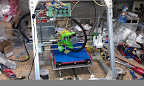
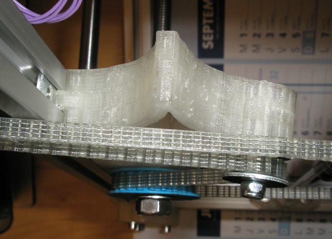
Ok it kinda works, but it's flexing a bit too much in the down direction in my opinion. I'll probably switch to your kind of idler when I'll receive a shorter belt, Buback.
It was a little too long at first, I crushed it by half a centimetre after heating with a hair dryer - might partially explain the down direction twisting.
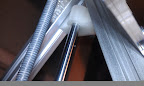
The tongue worked, not as clean as on your designs, but usable (see 2nd pic).
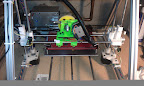
Also (see 3rd pic) the Z threaded rod bottom nuts are just flush with the ground. I'll probably need to do something about it once I place the machine on a rubber square to dampen vibrations as I usually do.
And yeah for me, when I forgot to put some nut in for the side 60° parts, I decided to add a couple of extra just in case, and they were handy for the motor on the other side, no disassembly this time ! It's probably a good suggestion to always leave a couple of spare nuts in any channel you're about to close.
On the bright side the Prism is far more easier to disassemble than any other design I've seen. Imagine the time needed if for instance you forget to mount your Y motor support on a regular reprap ? I did that on my Huxley (well not forgetting but mounting the bad way around) and I had already put threadlock everywhere when I realised... So thanks for the Prism Buback
Most of my technical comments should be correct, but is THIS one ?
Anyway, as a rule of thumb, always double check what people write.
It was a little too long at first, I crushed it by half a centimetre after heating with a hair dryer - might partially explain the down direction twisting.
The tongue worked, not as clean as on your designs, but usable (see 2nd pic).
Also (see 3rd pic) the Z threaded rod bottom nuts are just flush with the ground. I'll probably need to do something about it once I place the machine on a rubber square to dampen vibrations as I usually do.
And yeah for me, when I forgot to put some nut in for the side 60° parts, I decided to add a couple of extra just in case, and they were handy for the motor on the other side, no disassembly this time ! It's probably a good suggestion to always leave a couple of spare nuts in any channel you're about to close.
On the bright side the Prism is far more easier to disassemble than any other design I've seen. Imagine the time needed if for instance you forget to mount your Y motor support on a regular reprap ? I did that on my Huxley (well not forgetting but mounting the bad way around) and I had already put threadlock everywhere when I realised... So thanks for the Prism Buback
Most of my technical comments should be correct, but is THIS one ?
Anyway, as a rule of thumb, always double check what people write.
|
Re: Introducing the Prism Mendel March 27, 2012 10:35AM |
Registered: 13 years ago Posts: 601 |
Thanks! Yeah I always had a couple problems with my mendel stemming from my reluctance to go back and fix some initial assembly problems once the printer was all together.
Yeah, that's a good idea about the extra tnuts. I'll put it in the wiki. I have some extra tnuts in there but they slide around every time i move the printer (though thankfully that isn't too often), but it just occurred to me that i can use some extra computer screws to hold them in place. I think that some of them are m4, and they're short enough.
my z rod stack is, from bottom to top: nut>lock washer>printed pulley>washer>washer>washer>Nut>608 bearing>washer>nut.
I know there should be an extra washer between the lock washer and printed part, but there isn't room. :-)
This gives me about 1 mm between the z support block and 1mm or less clearance with the table. I assembled the stack separate, so that the bottom nut was definitely at the bottom of the rod, and then threadlocked the top nut in place. once that nut is locked, the spacing won't change.
Now, the clearance under the printer is determined by the 90 degree corner pieces, which are the thickness they are so that the 20mm m4 don't bottom out in the extrusion channel, and so that they're rigid. thicker piece will take longer to print, but will give more clearance.
Is this a good idea, or would it be better to recommend using a thin m8 nut at the bottom of the stack (which would give only an extra 1.5 mm clearance)?
Another issue, relating to the leadscrew wobble, that Nophead has mentioned on occasion is that the nut surfaces aren't likely to be perpendicular to the leadscrew axis (at least, not to tight tolerances). So, when you tighten down the nuts on the bearing, the bearing might be slightly off axis, leading to wobble.
|
Re: Introducing the Prism Mendel March 28, 2012 05:09AM |
Admin Registered: 12 years ago Posts: 2,569 |
Buback Wrote:
-------------------------------------------------------
> my z rod stack is, from bottom to top: nut>lock
> washer>printed pulley>washer>washer>washer>Nut>608
> bearing>washer>nut.
I had the same stacking, only with regular washer instead of the lock one (taking care of putting the "rough" side of the washer next to the pulley seems to grip the plastic enough).
I replaced one of the 3 washers located above the pulley with a thinner washer, now the nut now longer touch the table.
> This gives me about 1 mm between the z support
> block and 1mm or less clearance with the table. I
> assembled the stack separate, so that the bottom
> nut was definitely at the bottom of the rod, and
> then threadlocked the top nut in place. once that
> nut is locked, the spacing won't change.
The pulleys are nearly touching the support for me now with the thinner washer replacement, but not enough to make turning difficult. I expect the PLA will smooth itself after a little usage.
> Now, the clearance under the printer is determined
> by the 90 degree corner pieces, which are the
> thickness they are so that the 20mm m4 don't
> bottom out in the extrusion channel, and so that
> they're rigid. thicker piece will take longer to
> print, but will give more clearance.
>
> Is this a good idea, or would it be better to
> recommend using a thin m8 nut at the bottom of the
> stack (which would give only an extra 1.5 mm
> clearance)?
It could be nice to suggest that slim nut as a solution if the clearance to the table is a problem, but for me it doesn't seem mandatory.
On a side note I printed a shorter (removed 1 cm length) and stronger (4mm for the arms intead of 3, a lil bit more infill) version of my idler, now it's perfect size for my mendel sized belt (1100mm I believe) and doesn't flex down as much as before. I'll put the scad on thingiverse when I have a minute.
I gave a better look at how the tongue is printing, looks like only the first layer outer perimeter is falling off, everything else seems to get enough support from around.
Most of my technical comments should be correct, but is THIS one ?
Anyway, as a rule of thumb, always double check what people write.
|
Re: Introducing the Prism Mendel March 31, 2012 08:58AM |
Registered: 12 years ago Posts: 46 |
|
Re: Introducing the Prism Mendel April 02, 2012 09:06AM |
Registered: 12 years ago Posts: 40 |
Finally my prism started to print!
With 0.25 nozzle and T2.5 belt resolution is amazing. But it may take too long to print...
I tried that cable holders and they are loose, at least when printed on mine. I had to scale them down to 0.95, they attached better but break too easy, I probably would need stronger ones.
I would say I am not very impressed with Z moving by belt and one motor. My Prusa moves on Z much smoother. Maybe I need to do vertical adjustment.
To be continued...
 |
| From Prism |
With 0.25 nozzle and T2.5 belt resolution is amazing. But it may take too long to print...
I tried that cable holders and they are loose, at least when printed on mine. I had to scale them down to 0.95, they attached better but break too easy, I probably would need stronger ones.
I would say I am not very impressed with Z moving by belt and one motor. My Prusa moves on Z much smoother. Maybe I need to do vertical adjustment.
To be continued...
|
Re: Introducing the Prism Mendel April 02, 2012 10:53AM |
Registered: 13 years ago Posts: 601 |
looks great!
hmm cable holders fit fine on mine (misumi). Those are the second attempt; the first were too tight, so I made them a bit wider. Pure scaling might make the plastic too thin, so maybe it'd be better to alter the sketchup file (unless that's what you did)? You can try making them taller, and move the sides in a bit so it grips the extrusion more.
If you end up preferring a dual motor setup like with a prusa, there is an option i was originally considering. You can easily convert it over to a gear drive, like with the wades extruder where the motor drives the m8 bolt. You would need to design appropriate gears and print out a second z motor bracket.
You wouldn't have the motor coupling issues people have with prusas, but you might have some issues with printed gear inaccuracies. With a suitable gear ratio, though, those inaccuracies should be diminished, i would think.
|
Re: Introducing the Prism Mendel April 02, 2012 01:09PM |
Registered: 12 years ago Posts: 40 |
Buback Wrote:
-------------------------------------------------------
> looks great!
Thanks. I haven' done everything yet (bed is not attached yet, I am missing connectors on extruder, so I just temporarily soldered them) but looks very promising. I will probably try to sell my old prusa later, I am not sure if there is any demand for used one.
> hmm cable holders fit fine on mine (misumi). Those are the second attempt; the first were too tight, so I made them a bit wider.
Strange, my printer is calibrated pretty well I believe, which program you used to generate g-code? What layer thickness?
> Pure scaling might make the plastic too thin, so maybe it'd be better
> to alter the sketchup file (unless that's what you did)? You can try making them taller, and move the
> sides in a bit so it grips the extrusion more.
No I just scaled. I will try to edit them on sketchup later, I did not cuase that would require me to reboot to windows, so I just decided simply scale them for now. Maybe I will convert them to openscad and publish it.
> If you end up preferring a dual motor setup like
> with a prusa, there is an option i was originally
> considering. You can easily convert it over to a
> gear drive, like with the wades extruder where the
> motor drives the m8 bolt. You would need to design
> appropriate gears and print out a second z motor
> bracket.
Hmm I am afraid that will not work well for the same reason we had to put spring tension on belt.
> You wouldn't have the motor coupling issues people have with prusas, but you might have some issues
> with printed gear inaccuracies.
Strange, but I do not have any issues with coupling on my prusa, what is it?
|
Re: Introducing the Prism Mendel April 02, 2012 03:00PM |
Admin Registered: 12 years ago Posts: 2,569 |
Buback,
Here's the tongue with straight overhang, just out of the printer. Had to remove the single string dropping, and then worked fine.
I believe that now I have a fan on my printer it would maybe not even fall like that.
Edit uups forgot the pic.
Edited 2 time(s). Last edit at 11/22/2013 08:16AM by DeuxVis.
Most of my technical comments should be correct, but is THIS one ?
Anyway, as a rule of thumb, always double check what people write.
Here's the tongue with straight overhang, just out of the printer. Had to remove the single string dropping, and then worked fine.
I believe that now I have a fan on my printer it would maybe not even fall like that.
Edit uups forgot the pic.

Edited 2 time(s). Last edit at 11/22/2013 08:16AM by DeuxVis.
Most of my technical comments should be correct, but is THIS one ?
Anyway, as a rule of thumb, always double check what people write.
|
Re: Introducing the Prism Mendel April 04, 2012 05:20PM |
Registered: 12 years ago Posts: 18 |
Sorry guys, I've decided to go with a MendelMax instead. I do have about half of the parts printed in natural ABS at 100% fill. Some of the thicker parts do have warping, but I don't think it'll affect anything since they'res the legs at the bottom. Would anyone be interested in them? With some compensation for my plastic of course.
|
Re: Introducing the Prism Mendel April 08, 2012 11:12AM |
Registered: 12 years ago Posts: 46 |
Has anyone started on an openscad version yet ? I am about to start as I want to use the www.aluminium-profile.co.uk/ extrusion and need to have 6mm key strips and M5 screws.
I view it as a good project for learning scad but if it has already been done I would be better finding another useful project.
Edited 2 time(s). Last edit at 04/08/2012 11:26AM by TCase.
I view it as a good project for learning scad but if it has already been done I would be better finding another useful project.
Edited 2 time(s). Last edit at 04/08/2012 11:26AM by TCase.
|
Re: Introducing the Prism Mendel April 13, 2012 02:19PM |
Registered: 12 years ago Posts: 40 |
Sorry guys, I've decided to go with Prusa... Z-motor mounting. Here it is:
I had to move Z-rod couple mm towards center, so I had to redesign Z-top little bit:
But there are couple benefits to this design:
- I need 2 m4 bolts and nuts less
- Z-rod does not need adjustment on X coordinate anymore, it should self adjust properly.
Downside:
X became couple mm shorter.
I had couple issues with motor/rod holder, last design is printing, if it works I will publish it on thingiverse
 |
| From Prism |
I had to move Z-rod couple mm towards center, so I had to redesign Z-top little bit:
 |
| From Prism |
 |
| From Prism |
But there are couple benefits to this design:
- I need 2 m4 bolts and nuts less
- Z-rod does not need adjustment on X coordinate anymore, it should self adjust properly.
Downside:
X became couple mm shorter.
I had couple issues with motor/rod holder, last design is printing, if it works I will publish it on thingiverse
|
Re: Introducing the Prism Mendel April 13, 2012 08:12PM |
Registered: 12 years ago Posts: 40 |
OK, Looks like it is ready.
Here is how it looks like.
I was wrong, it saves not 2 m4 bolts and nuts but 4!
Anyway it works much smoother this way and it looks much better without that extra belt under bed, for cost of one extra stepper. It has less resolution than before, but I have more than enough with this thread already - 2269 steps/mm so one step 0.0004mm if did not miss something.
[www.thingiverse.com]
Edited 1 time(s). Last edit at 04/13/2012 08:39PM by rGlory.
Here is how it looks like.
 |
| From Prism |
I was wrong, it saves not 2 m4 bolts and nuts but 4!
Anyway it works much smoother this way and it looks much better without that extra belt under bed, for cost of one extra stepper. It has less resolution than before, but I have more than enough with this thread already - 2269 steps/mm so one step 0.0004mm if did not miss something.
[www.thingiverse.com]
Edited 1 time(s). Last edit at 04/13/2012 08:39PM by rGlory.


Sorry, only registered users may post in this forum.