help brainstorm a better bed leveling adjustment mechanisim
Posted by Buback
|
help brainstorm a better bed leveling adjustment mechanisim January 16, 2012 12:10AM |
Registered: 13 years ago Posts: 601 |
I hate the way the Mendel bed is leveled. Access is difficult and it tends to get out of level because of all the vibration. You would think a simple screw/spring would be foolproof.
I've thought of a couple ideas but haven't been able to flesh them out, so I'll throw them out here and see what you guys think. And if you have any ideas post them here and maybe we can come up with something that is much better.
1. First idea is to use a lever system to get more accuracy through mechanical advantage. I originally was thinking of the bones in the ear, except it'd be in reverse. A large adjustment would be needed to move the bed noticeably. This also means it wouldn't be easy for vibration to throw the bed out of alignment as quickly. The adjustment screw would be horizontal, so you could reach in with a screwdriver and adjust it without having to move the machine. A spring would be needed to keep tension on the plate.
2. The other idea i had was to use 4 of leaf springs to support the bed. one end of the spring would be fixed, and the other would have a horizontal adjustment screw. As you tightened the screw, the tension would increase and the spring would get rounder, raising the bed. I don't know if this is any better than the regular method though, except for being able to adjust it from the side.
I was also thinking about leveling procedure after reading nophead's posts about mendel90. A 3 point adjustment system would make adjustment much easier; two point in line with X axis (or Y) on one side, and the other point on the opposite side in the middle of the bed, like a T shape. First you level the one side, the top of the T, then move the head to the bottom of the T and level, and the whole bed should be level. Like Nophead, I've found that each adjustment you make tends to throw off the others with 4 points. Perhaps this would still happen, but at least it's one less point to contend with.
|
Re: help brainstorm a better bed leveling adjustment mechanisim January 16, 2012 02:23AM |
Registered: 12 years ago Posts: 73 |
I will describe my levelling system... I find it an improvement over the standard.
I have two main enhancements over the standard, the first being a small addition to the levelling bolts. Rosette Screw This makes levelling a whole lot less of a pain to do.
In order to make the process less frustrating I originally moved from having four sprung bolts at each corner to having three. Two on the left hand corners of the bed and one on the center right. This made levelling much easier, but Ihad a problem in that the upward pressure of the springs was unequal. I thought about sourcing a stronger spring for the right hand side but instead did this.
On the right hand side there are now three bolts between the Y carriage and the print bed. The two on the corners are sprung, but their nuts are left at the far extreme of the bolt i.e. in themselves they do not tension the springs. In the middle is the tensioning bolt. To sum it up from a spring point of view it looks like the original with a spring on each corner. Fro an adjustment point of view I am using a three point adjustment.
I am sure that there are better ways to do it, but this improved on the original and used only one more nut and bolt to do so.
|
Re: help brainstorm a better bed leveling adjustment mechanisim January 16, 2012 06:03AM |
Registered: 13 years ago Posts: 228 |
I think too a three point adjustment system is way easier to manage than a four point.
The diameter of the supporting pieces (currently m3 blts and a spring over them) should probably be increased.
Nophead eliminated the springs in his design, this certainly helps with rigidity
I like the idea of a lever system - need to balance complexity and function, though.
...
The diameter of the supporting pieces (currently m3 blts and a spring over them) should probably be increased.
Nophead eliminated the springs in his design, this certainly helps with rigidity
I like the idea of a lever system - need to balance complexity and function, though.
...
|
Re: help brainstorm a better bed leveling adjustment mechanisim January 16, 2012 11:17AM |
Registered: 13 years ago Posts: 601 |
I have had too many z crashes to forgo springs. Nothing damaging, thankfully, but enough to give me pause. But he certainly is right that it causes wobble, but the wobble (at least mine) is x-y, not z, which i think is also caused by the extra play in the holes and the length of the screws.
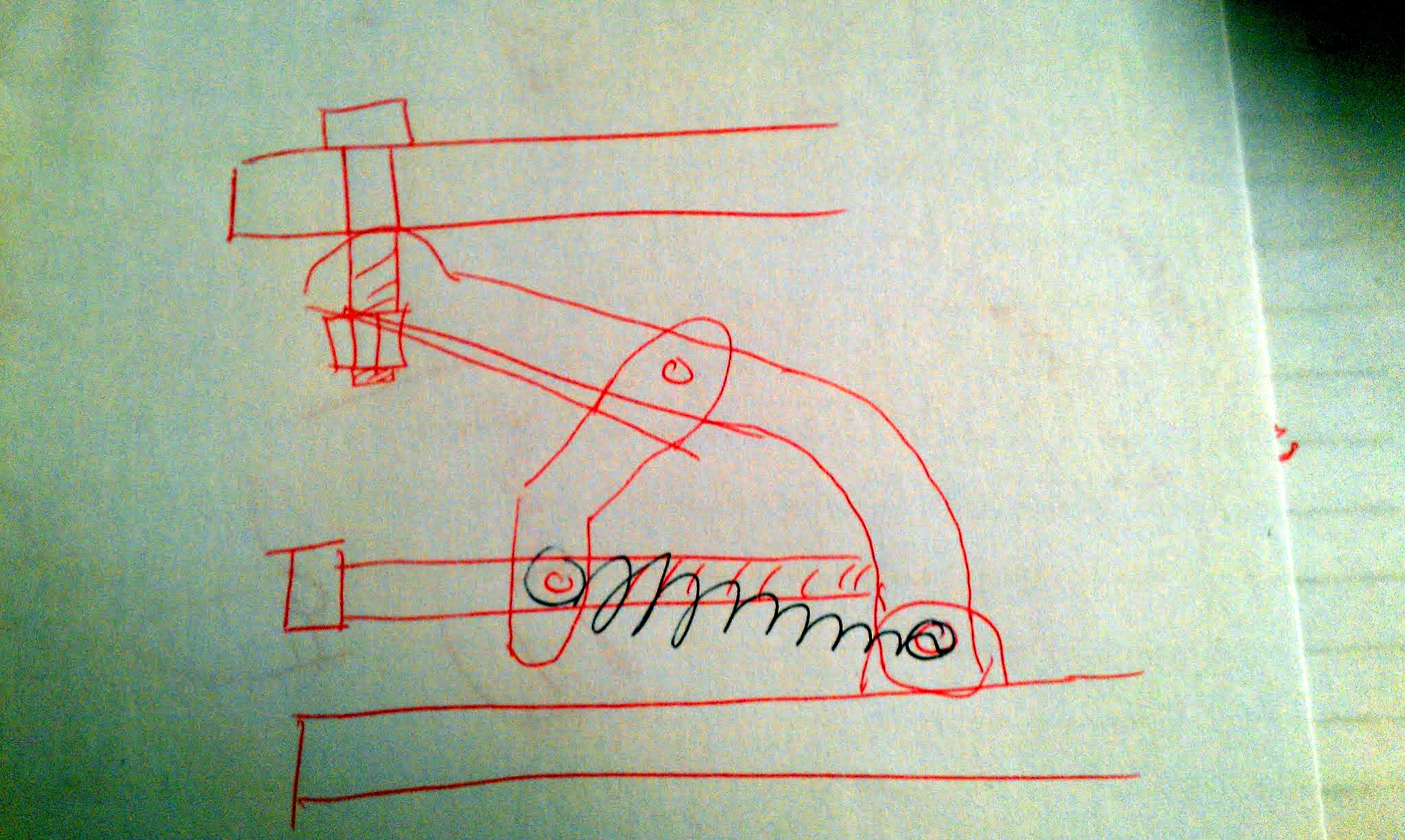
I was thinking about this last night in bed, and i think with a lever-like system we can use tension springs instead of compression springs. I don't know if that would make a difference, but it seems to me that the tension spring would vibrate more like a guitar string when tensioned.
I've attached a sketch of a lever system. the tension spring is in the black ink.
Edit: yeah complexity is an issue, since it adds parts which might be finicky to print. They'd also melt on a headed bed :-(
Edited 1 time(s). Last edit at 01/16/2012 11:24AM by Buback.
|
Re: help brainstorm a better bed leveling adjustment mechanisim January 16, 2012 11:31AM |
Registered: 13 years ago Posts: 601 |
|
Re: help brainstorm a better bed leveling adjustment mechanisim January 16, 2012 03:21PM |
Registered: 13 years ago Posts: 228 |
@Buback. I am not excessively worried about crashes (yes they happen) because I made a two parts extruder carriage, with the upper part held down to the lower by magnets (horizontal plane play is prevented by tubular boltheads). So in case the hot end touches the bed with some force, it just pops up. Pictured here [www.thingiverse.com] (IMHO this design is printable too, but I wanted plywood where melts happen)
I have the bed on m3 bolts and springs, bolt heads under the sheet, nuts on top of the heatbed. The bolt heads and accompanying washers are thoroughfully epoxied to the MDF sheet: the bolts cannot move at all, so there is very little or none horizontal play.
Note I had to (carefully) drill the heatbed (mk1) which has ridiculously small holes at the corners. Seems this "feature" has not been revised with mk2, and there is very little clearance to traces. This would be a problem with m6 bolts. Of course this would not be a problem had I gone the DIY way with the heated bed (last year 20x20 pcb sheet wasn't found on eBay)
|
Re: help brainstorm a better bed leveling adjustment mechanisim January 25, 2012 02:40PM |
Registered: 13 years ago Posts: 601 |
Similar to the lever idea, i was thinking about trying to make something like a scissor jack with toggle bolts.
Toggle bolts are a kind of spring action nut used to hang stuff from drywall. I actually had to look up the name on wikipedia. this is what i'm talking about, on the left:
I doubt the springs are strong enough to hold up the bed, but this might be less complex than a fully printed lever design.
Toggle bolts are a kind of spring action nut used to hang stuff from drywall. I actually had to look up the name on wikipedia. this is what i'm talking about, on the left:

I doubt the springs are strong enough to hold up the bed, but this might be less complex than a fully printed lever design.
|
Re: help brainstorm a better bed leveling adjustment mechanisim January 27, 2012 04:13PM |
Registered: 13 years ago Posts: 61 |
I would like to throw out an alternative solution to the same problem:
I would like to have an option / test program to mount an endstop on my extruder temporarily, measure the four corners, and then have it tell me which corner needs to increase or decrease. I would turn a few bolts, and repeat until happy.
Either that, or some way to modify the zcode like nophead did in order to make up for it entirely in software. The benefit of the way he did it is that the bed changes size with heat and humidity. By measuring and modifying the bed height you can really ensure the best possible print on any given day / hour.
[hydraraptor.blogspot.com]
If we had machines where the bed was stationary, then this bed leveling operation could be so much simpler.
|
Re: help brainstorm a better bed leveling adjustment mechanisim January 27, 2012 05:45PM |
Registered: 13 years ago Posts: 601 |
This will get you started:
[adventuresin3-dprinting.blogspot.com]
Another option is to just go full-on servo controled bed leveling. If it allowed me to print a bed full of parts consistently, it would pay for itself soon enough.
[adventuresin3-dprinting.blogspot.com]
Another option is to just go full-on servo controled bed leveling. If it allowed me to print a bed full of parts consistently, it would pay for itself soon enough.
|
Re: help brainstorm a better bed leveling adjustment mechanisim January 27, 2012 10:58PM |
Registered: 13 years ago Posts: 485 |
I have a notion of using the nozzle itself to probe the bed by mounting the extruder on a hinge.
It's almost like the quick release carriage Lanthan mentioned, the but the extruder is on a hinge instead of magnets. One side of the extruder is hinged, the other rests on a switch. The weight of the stepper and extruder should be enough to keep the switch closed, until the nozzle touches the bed during a negative Z move. After contact, continued negative Z motion would lower the carriage away from the extruder, opening the switch while the extruder swings on the hinge. Depending on what you are doing, this switch opening will signal either Z home or probe (nozzle) contact. Since the nozzle itself is the probe, Z=0 will always mean that the nozzle is just touching the bed. There is no intermediate measurement between the nozzle and a contact switch. If this is always done just before extruding the skirt, with everything hot, then the first layer height should be very consistent.
The idea also offers the incidental advantage of eliminating the need for bed springs. The carriage will swing on the hinge instead of driving into the bed. This would generate a Z home signal, so if the firmware is monitoring for Z home, the Z axis should just stop. So the springs are no longer necessary as a fail-safe.
Of course, all that doesn't offer a better mechanism for making the actual adjustment.
------------------------
For adjusting the bed, I'm thinking of a device I saw on a machine almost 15 years ago. I've never seen it anywhere else, so I had to give it a name. I called it a differential pitch adjusting screw. The sketch below turns the idea inside out to use two standard screws instead of the single custom-threaded screw I saw (and later used several times for work).
As you turn the adjuster, it moves on the M5 screw at 0.8 mm per turn, and on the M4 screw at 0.7 mm per turn. The result is that the screws move together or apart 0.1 mm per turn of the adjuster, 0.025 per 1/4 turn, and so on. This should make fine adjustments fairly easy, using standard coarse-pitch screws in a fairly stable package.
The sketch is fairly crude, and makes the whole thing longer than it really needs to be. Even if it does need to be longish, a Y carriage could be designed to make room for it. If the adjuster fits tightly on the screws, the resulting self-locking action might obviate the need for the jam nut. Coarse adjustments could be made by loosening and turning the M4 screw.
If you like it, please implement it. I won't have time to try it for a few months. I have too many other (non-RepRap) projects to finish first.
Edited 2 time(s). Last edit at 01/27/2012 11:02PM by Dale Dunn.
It's almost like the quick release carriage Lanthan mentioned, the but the extruder is on a hinge instead of magnets. One side of the extruder is hinged, the other rests on a switch. The weight of the stepper and extruder should be enough to keep the switch closed, until the nozzle touches the bed during a negative Z move. After contact, continued negative Z motion would lower the carriage away from the extruder, opening the switch while the extruder swings on the hinge. Depending on what you are doing, this switch opening will signal either Z home or probe (nozzle) contact. Since the nozzle itself is the probe, Z=0 will always mean that the nozzle is just touching the bed. There is no intermediate measurement between the nozzle and a contact switch. If this is always done just before extruding the skirt, with everything hot, then the first layer height should be very consistent.
The idea also offers the incidental advantage of eliminating the need for bed springs. The carriage will swing on the hinge instead of driving into the bed. This would generate a Z home signal, so if the firmware is monitoring for Z home, the Z axis should just stop. So the springs are no longer necessary as a fail-safe.
Of course, all that doesn't offer a better mechanism for making the actual adjustment.
------------------------
For adjusting the bed, I'm thinking of a device I saw on a machine almost 15 years ago. I've never seen it anywhere else, so I had to give it a name. I called it a differential pitch adjusting screw. The sketch below turns the idea inside out to use two standard screws instead of the single custom-threaded screw I saw (and later used several times for work).

As you turn the adjuster, it moves on the M5 screw at 0.8 mm per turn, and on the M4 screw at 0.7 mm per turn. The result is that the screws move together or apart 0.1 mm per turn of the adjuster, 0.025 per 1/4 turn, and so on. This should make fine adjustments fairly easy, using standard coarse-pitch screws in a fairly stable package.
The sketch is fairly crude, and makes the whole thing longer than it really needs to be. Even if it does need to be longish, a Y carriage could be designed to make room for it. If the adjuster fits tightly on the screws, the resulting self-locking action might obviate the need for the jam nut. Coarse adjustments could be made by loosening and turning the M4 screw.
If you like it, please implement it. I won't have time to try it for a few months. I have too many other (non-RepRap) projects to finish first.
Edited 2 time(s). Last edit at 01/27/2012 11:02PM by Dale Dunn.
|
Re: help brainstorm a better bed leveling adjustment mechanisim January 29, 2012 05:32AM |
Registered: 13 years ago Posts: 818 |
Dale Dunn Wrote:
-------------------------------------------------------
> For adjusting the bed, I'm thinking of a device I
> saw on a machine almost 15 years ago. I've never
> seen it anywhere else, so I had to give it a name.
> I called it a differential pitch adjusting screw.
> The sketch below turns the idea inside out to use
> two standard screws instead of the single
> custom-threaded screw I saw (and later used
> several times for work).
I think that's a similar idea to what Nophead has implemented on Mendel90 - Using simple threaded metal spacers and nuts to screw and lock - no springs.
From Nophead's blog - Mendel90
I'm implementing a similar system using a stack of 2 x small metal M4 threaded spacers with an M4 nut and M4 locknut in the middle and short section of M4 thread on my next machine, You turn the lock-nut in the middle to make the latform go up and down, then fix it by screwing the other M4 nut into one of the pilars. I don't like having springs on the bed -as long as your X carriage is sprung on the Z holders,it's not a big problem even if you do have a head crash.
You could do the same with M3 components.
[richrap.blogspot.com]
-------------------------------------------------------
> For adjusting the bed, I'm thinking of a device I
> saw on a machine almost 15 years ago. I've never
> seen it anywhere else, so I had to give it a name.
> I called it a differential pitch adjusting screw.
> The sketch below turns the idea inside out to use
> two standard screws instead of the single
> custom-threaded screw I saw (and later used
> several times for work).
I think that's a similar idea to what Nophead has implemented on Mendel90 - Using simple threaded metal spacers and nuts to screw and lock - no springs.

From Nophead's blog - Mendel90
I'm implementing a similar system using a stack of 2 x small metal M4 threaded spacers with an M4 nut and M4 locknut in the middle and short section of M4 thread on my next machine, You turn the lock-nut in the middle to make the latform go up and down, then fix it by screwing the other M4 nut into one of the pilars. I don't like having springs on the bed -as long as your X carriage is sprung on the Z holders,it's not a big problem even if you do have a head crash.
You could do the same with M3 components.
[richrap.blogspot.com]
|
Re: help brainstorm a better bed leveling adjustment mechanisim January 29, 2012 09:00AM |
Registered: 12 years ago Posts: 139 |
|
Re: help brainstorm a better bed leveling adjustment mechanisim January 29, 2012 05:23PM |
Registered: 13 years ago Posts: 485 |
richrap Wrote:
-------------------------------------------------------
> I think that's a similar idea to what Nophead has
> implemented on Mendel90 - Using simple threaded
> metal spacers and nuts to screw and lock - no
> springs.
That standoff construction is what suggested to me the idea to turn the differential pitch screw idea into two screws of different pitch connected by a coupler. Turn the coupler, and you get very fine movements. I suppose someone out there might sell M4 to M5 adapters of some kind.
|
Re: help brainstorm a better bed leveling adjustment mechanisim February 29, 2012 07:29PM |
Registered: 12 years ago Posts: 11 |
I have an idea!
1. Buy a turnbuckle [www.mcmaster.com]
2. Throw away the eye bolts, keep the middle piece
3. Drill out the left hand threaded side, and thread it (right handed) with a slightly larger size
4. Put bolts in both sides, attach to Y carriage and bed
5. ?????
6. Level beds!
You would want really small turnbuckles, and the bed would be really high above the Y carriage. An alternative with not nearly as much adjustment would be to solder/braze/weld/glue 2 nuts together of different sizes. Just make sure the adhesive doesn't get inside.
Edited 1 time(s). Last edit at 02/29/2012 07:30PM by shardbearer.
|
Re: help brainstorm a better bed leveling adjustment mechanisim March 01, 2012 09:23PM |
Registered: 13 years ago Posts: 485 |
|
Re: help brainstorm a better bed leveling adjustment mechanisim March 01, 2012 11:33PM |
Registered: 13 years ago Posts: 601 |
|
Re: help brainstorm a better bed leveling adjustment mechanisim August 04, 2012 07:37AM |
Registered: 12 years ago Posts: 46 |
Doesn't RAMPS have 4 x Servo headers. So thats 1 for Nopheads Genius ZProbe and 3 x 9g Servos? Whole cost £10 / $15? A quick 4 corner probe and a 3 point servo adjust before you print and off we go.
You could have a pre-leveling routine with the z probe hooked up in parallel to the z stop if you wanted so people could bolt it on as a complete kit without touching any of their existing stuff. The z probe would retract and you could let the existing optos/microswitches take care of the bed distance stuff.
Man If there was space for one more servo you could have a filament wipe scoop as well. couple that with an automated build platform and you wouldnt need to touch a thing. We could all go home lol.
|
Re: help brainstorm a better bed leveling adjustment mechanisim August 06, 2012 04:04AM |
Admin Registered: 16 years ago Posts: 13,886 |
... i think, a pure mechanical methode with fixing clamps should be the easisest/DIY-ablest way.
I'll set the table on three rods, that will rest in tubes with a clamp fixture on the side and springs, strong enough to hold the weight of the empty bed in this points.
Then insert a (removable, adjustable) probe-stick with the desired height-measure in the extruder head, drive (above the bed) to one of the rod-positions in XY, release the clamp, so the bed is 'floating', move the head down to the defined Z-position, so the probe-stick will push the bed in position and fix the clamp.
Repeat this for the other two rod-positions and the bed is nearly level ... repeat all three 'fittings' for perfect levelling, if the first run wasn't precise enough (when starting with a tilted bed)
Viktor
--------
Aufruf zum Projekt "Müll-freie Meere" - [reprap.org] -- Deutsche Facebook-Gruppe - [www.facebook.com]
Call for the project "garbage-free seas" - [reprap.org]
|
Re: help brainstorm a better bed leveling adjustment mechanisim August 06, 2012 08:08AM |
Registered: 12 years ago Posts: 38 |
Main problem with bed positioning is 4 point bed leveling. Becouse for plane u need 3 point and bed is overconstrained... Btw. spring type of bed leveling is better for me. Personally i use much stronger ones. It prevents head/bed colision danger + u can set bed plane +-1mm. Only problem for me should be overhanging of bolts to print area.
|
Re: help brainstorm a better bed leveling adjustment mechanisim August 06, 2012 02:14PM |
Registered: 12 years ago Posts: 46 |
I agree with what you guys are saying, but I'm sure there's a lot of people out there on the fence reading about the constant woes people have with keeping the bed level, keeping things calibrated, making sure temperatures are right and mosfets aren’t too warm etc who simply won't jump in until things are easy enough for them to give it a shot. We all find our own techniques and workarounds, and our ability to find different working solutions speaks to our engineering abilities and problem solving skills (I'm a "4 point thick paper method" with supporting springs man myself), but I bet there's a stack of 3d designers that could inject a wealth of modelling and design expertise to the reprap movement that need something that will do some of the hard work for them. Do you guys think something like the attached would work and help with that?

|
Re: help brainstorm a better bed leveling adjustment mechanisim August 06, 2012 03:52PM |
Registered: 12 years ago Posts: 38 |
udimension profi printers uses sensor, measuring inserted plastic table and then correcting raft.
Btw. if u do not need to correct z axis position, only make table horizontal, u need just 2 positioning points (servos etc). And i would move them to the edge of table.
Edited 1 time(s). Last edit at 08/07/2012 07:17AM by zemciko.
Btw. if u do not need to correct z axis position, only make table horizontal, u need just 2 positioning points (servos etc). And i would move them to the edge of table.
Edited 1 time(s). Last edit at 08/07/2012 07:17AM by zemciko.
|
Re: help brainstorm a better bed leveling adjustment mechanisim August 08, 2012 08:59AM |
Registered: 12 years ago Posts: 46 |
I did think about using two points but I decided that adjusting Z in pronterface with a button and reliable adjustment resolution would be easier for people rather than adjusting the mechanics. The only requirement would be ensuring the z probe matches the hot end.
I looked at distance sensors as another avenue of enquiry. I looked at ultrasonic, ir and laser distance sensors but the cheap ones lacked resolution and the lasers that would work would be so expensive they'd not be available to many.
I looked at distance sensors as another avenue of enquiry. I looked at ultrasonic, ir and laser distance sensors but the cheap ones lacked resolution and the lasers that would work would be so expensive they'd not be available to many.
|
Re: help brainstorm a better bed leveling adjustment mechanisim August 08, 2012 10:40AM |
Registered: 13 years ago Posts: 601 |
the benifit of servos is that they can be made to go back to their set position every time you turn on the machine (with, i imagine, some type of control curcuit). So, as long as the machine hasn't changed, everything should be level and alligned, even if you have to set the inital allignment manually.
Of course, if you are skipping steps or the leadscrew is binding, you'll still have problems between prints. But just being able to move the extruder to an alligment point and press a button to raise or lower the bed would be wonderful. An auto leveling routine with sensors would be nice but not necessary for the initial design.
Of course, if you are skipping steps or the leadscrew is binding, you'll still have problems between prints. But just being able to move the extruder to an alligment point and press a button to raise or lower the bed would be wonderful. An auto leveling routine with sensors would be nice but not necessary for the initial design.
|
Re: help brainstorm a better bed leveling adjustment mechanisim August 15, 2012 05:45PM |
Registered: 12 years ago Posts: 46 |
Well I've ordered 3 x Continuous Rotation servos so I can play around with it. As you say Buback, if you could only adjust the bed from the host software that would be an advantage over where we are now. I know these might add weight etc etc etc but until someone tries it we don't know for sure.
My plan is to plug these into the ramps and see if I can get each of them moving from GCODE commands, then in pronterface I can make 6 buttons, for up and down on each of the servos for easy adjustment.
Thats the plan, lets see if it works. Either we'll all have servo adjusted beds by christmas, or I just wasted £30 lol. At least I can use them for a robot if this doesnt work hey!
|
Re: help brainstorm a better bed leveling adjustment mechanisim August 25, 2012 06:03PM |
Registered: 12 years ago Posts: 46 |
Well I made some progress on this. The servos arrived this morning, took them a while. I made a start on the code as below, but it seems I the servo and stepper libraries cant co-exist out of the box. I get the error "multiple definitions of __vector_17", which I reckon is down to the fact that both libraries have a deffinition for TIMER1_COMPA_vect.
Since I've only been coding on arduino for the last 30 mins I obviously need to do some more reading, and I will. If anyone is interested/curious about the code I did so far, it is below. Not much I know, but I think if I can get past the error above, it should hopefully turn the servos at least. If it does that then I can start on the cool stuff like printing the gears and platform for the auto-leveler.
Since I've only been coding on arduino for the last 30 mins I obviously need to do some more reading, and I will. If anyone is interested/curious about the code I did so far, it is below. Not much I know, but I think if I can get past the error above, it should hopefully turn the servos at least. If it does that then I can start on the cool stuff like printing the gears and platform for the auto-leveler.
--- pins.h --- L303

#ifdef AUTO_BED_ADJUSTMENT
  #define SERVO_0 11
  #define SERVO_1 6
  #define SERVO_2 5
  #define SERVO_3 4
#endif

--- Configuration.h L203
#define AUTO_BED_ADJUSTMENT

---Marlin.pde L115
// M600 - move bed levelling servos plus or minus in degrees e.g. M600 -1 1 0 (m600 servo_1 servo_2 servo_3)
// M601 - set servo angular speed e.g. M601 S180 = full cw / M601 S90 = off / M601 S0 = full ccw
// M602 - set servo angular speed e.g. M602 S180 = full cw / M602 S90 = off / M602 S0 = full ccw
// M603 - set servo angular speed e.g. M603 S180 = full cw / M603 S90 = off / M603 S0 = full ccw
// M604 - set servo angular speed e.g. M604 S180 = full cw / M604 S90 = off / M604 S0 = full ccw

--Marlin.pde L41
#include

-- Marlin.pde L140

#ifdef AUTO_BED_ADJUSTMENT

  Servo servoController_0;
  Servo servoController_1;
  Servo servoController_2;
  Servo servoController_3;

#endif


--Marlin.pde L318

#ifdef AUTO_BED_ADJUSTMENT
  servoController_0.attach(SERVO_0);
  servoController_1.attach(SERVO_1);
  servoController_2.attach(SERVO_2);
  servoController_3.attach(SERVO_3);
#endif


---Marlin.pde :1295
#ifdef AUTO_BED_ADJUSTMENT

    case 600: // M600 - move bed levelling servos plus or minus in degrees e.g. M600 -1000 350 0 (m600 servo_1 servo_2 servo_3)
    {
            // TODO
    }

    break;
    case 601://  M601 - set servo angular speed e.g. M601 S180 = full cw / M601 S90 = off / M601 0 = full ccw
    {
      if (code_seen('S')) servoController_0.write(code_value());
    }
    break;
    case 602: // M602 - set servo by angular speed e.g. M602 S180 = full cw / M602 S90 = off / M602 0 = full ccw
    {
      if (code_seen('S')) servoController_1.write(code_value());
    }
    break;
    case 603: // M603 - set servo by angular speed e.g. M603 S180 = full cw / M603 S90 = off / M603 0 = full ccw
    {
      if (code_seen('S')) servoController_2.write(code_value());
    }
    break;
    case 604: // M604 - set servo angular speed e.g. M604 S180 = full cw / M604 S90 = off / M604 0 = full ccw
    {
      if (code_seen('S')) servoController_3.write(code_value());
    }
    break;
#endif
|
Re: help brainstorm a better bed leveling adjustment mechanisim August 26, 2012 07:46PM |
Registered: 11 years ago Posts: 525 |
Love the servo idea but my bed doesn't need to be aligned every print.
I am on a quest to maximise the print area so I am thinking of countersinking the bed screws into an aluminium subframe and mount the pcb-style bed heater above it. I want my glass print surface to have 210mmx210mm and to do that it needs to run over the pcb heater mounting screws. I plan to glue a sheet of 210mmx210mm glass direct to the pcb heater.
The underside is glued to a subframe that has countersunk M3 or M4 machine screws, nuts, short springs, y-carriage frame then thumbwheels with nuts recessed into the bottom. Something like this...
Could add a ratchet to the thumbwheel to prevent vibration movements.
Edited 2 time(s). Last edit at 08/26/2012 11:31PM by Wired1.
_________________________________________________________________________________________
Richmond, New Zealand
Thingiverse ~ YouTube
I am on a quest to maximise the print area so I am thinking of countersinking the bed screws into an aluminium subframe and mount the pcb-style bed heater above it. I want my glass print surface to have 210mmx210mm and to do that it needs to run over the pcb heater mounting screws. I plan to glue a sheet of 210mmx210mm glass direct to the pcb heater.
The underside is glued to a subframe that has countersunk M3 or M4 machine screws, nuts, short springs, y-carriage frame then thumbwheels with nuts recessed into the bottom. Something like this...

Could add a ratchet to the thumbwheel to prevent vibration movements.
Edited 2 time(s). Last edit at 08/26/2012 11:31PM by Wired1.
_________________________________________________________________________________________
Richmond, New Zealand
Thingiverse ~ YouTube
|
Re: help brainstorm a better bed leveling adjustment mechanisim August 27, 2012 07:13AM |
Registered: 11 years ago Posts: 525 |
Or this. I have just made myself a one piece printable y-carriage One-piece printable y-carriage that is as big as you can print so this would hang out from that. The total adjustment only needs to be 1-2mm total so the slop in the screws would compensate for the slight angle in them as they tilt. The top springs are just to allow the hotend to nose dive into the bed without damage, the bottom ones keep it all tight. Nylocs on the top screws might help.
Edited 1 time(s). Last edit at 08/27/2012 07:14AM by Wired1.
_________________________________________________________________________________________
Richmond, New Zealand
Thingiverse ~ YouTube

Edited 1 time(s). Last edit at 08/27/2012 07:14AM by Wired1.
_________________________________________________________________________________________
Richmond, New Zealand
Thingiverse ~ YouTube
|
Re: help brainstorm a better bed leveling adjustment mechanisim August 27, 2012 10:05AM |
Registered: 12 years ago Posts: 46 |
I'm possibly going to move this idea to another thread because I'm conscious of the fact that I'm probably hijacking this a little. I know there's a limited audience for the automatic leveller idea, and there's some great mechanical ideas here, but thought I'd share some progress on it.
There's a video below of where I'm at. I got 4 servo's hooked up to Ramps 1.4. There's one 180degree servo for a probe and 3 x continuous servo's for the levelling. It's running on a simple arduino sketch at the moment which is feeding in a modified sine wave to the servos for test purposes, so there's some work to do integrating the servo library into Marlin, but it sorta shows it can be done.
Ramps 1.4 with servos

|
Re: help brainstorm a better bed leveling adjustment mechanisim October 06, 2012 07:16PM |
Registered: 13 years ago Posts: 6 |
Really like this idea but i have issues with springs. they seem create to much play so what about a hinge at the top.... only issue i see with that is, levers and fixed points don't really get along to well, Hinge would change distance as it moved up and down.
|
Re: help brainstorm a better bed leveling adjustment mechanisim October 06, 2012 10:15PM |
Registered: 11 years ago Posts: 525 |
Yes it is hard to make moving parts without some slop, especially printed parts. Like your hinged heater mounts, if they could glue directly to the heater and not need a screw it would let you run a slightly larger sheet of glass.
_________________________________________________________________________________________
Richmond, New Zealand
Thingiverse ~ YouTube
_________________________________________________________________________________________
Richmond, New Zealand
Thingiverse ~ YouTube

Sorry, only registered users may post in this forum.