 Kiwi-M5 Mendel Battle Tank! (was: Rotorua RepRap)
Posted by RepRot
|
Kiwi-M5 Mendel Battle Tank! (was: Rotorua RepRap) January 06, 2011 03:51PM |
Registered: 14 years ago Posts: 128 |
Some photos of my Kiwi-M5 Mendel Battle Tank 3D printer.
This Reprap based machine has been built with:
- Bullet resistant material.
- Driven with five powerful 24 volt stepper motors.
- Arduino Mega processor controller.
- Power plant consisting of dual power supplies, 563 watt (main supply) and 150 watt (heated bed).
- Massive all-up weight of 25 Kg.
- Long wheel base (Top 2 threaded shafts are 710mm long).
- Loaded and armed with 100 metres of 3 mm diameter filament ammunition.
- Powerful direct drive filament loading stepper motor .
- 0.5 mm diameter howitzer extruder barrel.
- Target area (Print) - X axis 200 mm - Y axis 200 mm - Z axis 110 mm.
This machine now begining field trials for future battles. In other words it's printing and some fine tuning is being carried out.
Having acquired some off-cuts of 10 mm clear polycarbonate sheets, I thought this would be a good material to try and build a Repstrap type of machine.
Polycarbonate is what CD’s and DVD’s are made of. Among other things it is also used for bullet resistant windows.
Polycarbonate is a very strong material, it can be easy cut with a hand saw. It can be machined drilled or cut provided machine cutting speeds are kept low to reduce temperature build up. Screw threads can easy be taped by hand.
Note: Polycarbonate is not normally cut using a laser cutter due to the high level of toxic fumes that is produced, however it can be cut by using a CNC water jet cutter.
Polycarbonate is not a cheap product to buy price is around NZ$460 per square meter for 10 mm thick sheet pieces.
My aim was to build most of the frame parts from the 10 mm Polycarbonate sheets with the least amount of machining. This means some parts will appear to be over engineered.
Due to the complexity of the design, a lot of the work has been, design and build as you go. This has meant some parts have been made and discarded until the design worked. Other designed parts were too hard to machine and a different design part was then made.
The 10 mm polycarbonate worked out well in the end for mounting the standard Mendal axis support bearings.
Trying to mount the 3 guide bearings at 120 degrees with only using 10 mm thick material was going to be difficult, however I found that the bearings being 13 mm diameter could be mounted at 90 degrees to each other, e.g. a bearing could be bolted on the flat surface and then the other bearing could be bolted on the edge using a 4 mm bolt, this then gives each bearing a 1.5 mm exposure on each side of the 10 mm polycarbonate sheet. (See pictures of Y and Z axis).
I also found that the 4mm bolts that hold the 13 mm bearings could be placed in a drill chuck and by using a metal file, the thread could be filed away allowing the bearing to be finely adjusted.
Polycarbonate has a degree of spring tension which can be used keep the ball bearing running against guiding surface.
A lot of the parts were hand cut then machined in a drill mill. A drill mill is a bit like a bench electric drill press. It has a vice that can be moved by hand in X & Y axis direction. The drill chuck is replaced with a tool holder that holds slot drills that can be used to cut and shape the polycarbonate. If you use a drill chuck to hold a slot drill, the sideways force with cutting will cause the drill chuck to fall off the drill shaft.
A mini lathe was used for the odd part - Z axis threaded drive shafts - this was to allow the couplings to be fitted to connect the stepper motors, - Filament spool hub - Filament guides, these are used in the filament spool hose connector that connects to the extruder drive assembly.
Frame:
All of the Mendal frame brackets have been constructed using 2 pieces of machined 10 mm Polycarbonate. This gives a 20 mm thickness for each bracket. The 8 mm threaded shafts nuts then hold these two frame parts together.
The basic Mendal frame design was increased at one end to allow room for two power supplies, (Main power supply and a heated bed transformer).
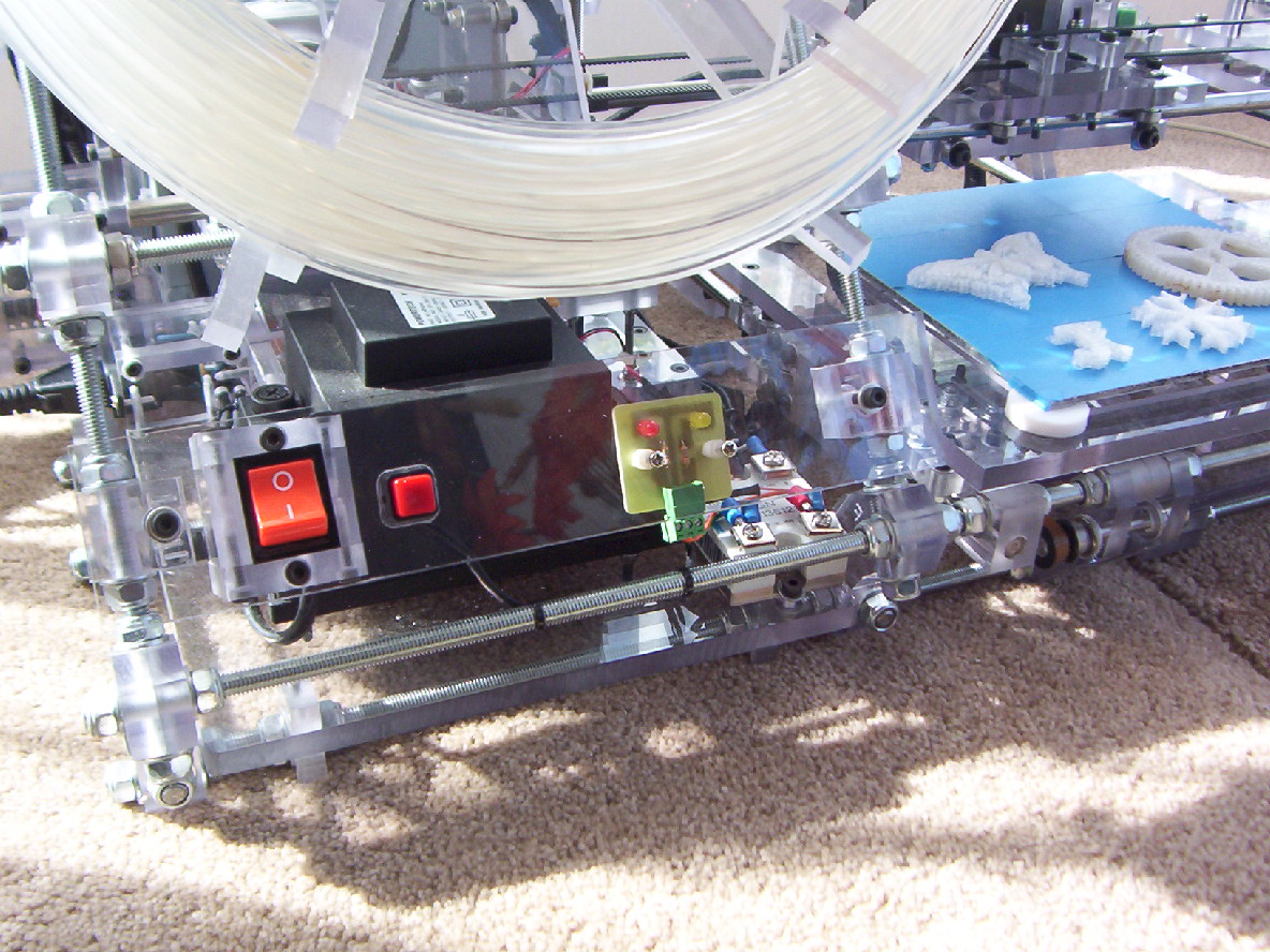
The additional frame length also allowed room to mount a spool of filament material as well as being able to mount the electronics and power On-Off/Reset switches/LED heater display PCB away from the print area.
Increasing the Mendal frame length has increased the overall rigidity of the frame and added to the all up weight to counter vibrations from the movement of the different moving axis parts.
There are around 150 8 mm diameter Nylock nuts plus washers on this machine. The Nylock nuts were used more for looks. The 8 mm Nylock nuts were a pain to move along the threaded shafts, often I used an electric hand drill turning the threaded shaft and using a spanner to hold the Nylock nuts.
Around 200 4mm diameter bolts of 3 different lengths (plus some nuts and washers) have also been used. Some of the longer 4 mm bolts sourced didn't have thread along their entire length. I used a 4 mm die to increase the length of thread. This was relatively easy as the bolts already had thread to start with.
Power supplies:
The mains power (230 Volt AC) is connected to the machine via a cable lead plug-able power socket. Power is then feed to a power switch which is fitted to the front of the machine. the switched power is then feed onto the two power supplies.
An earth mains power connection from the main power supply is connection to the Mendal frame. All 8 mm threaded shafts of the machine are bonded together to reduce EMF interference. To bond the 8 mm threaded shafts, a wire has been placed under the 8 mm nuts at frame junction points to connect all the 8 mm threaded shafts together.
A 563 watt power unit that outputs +5 volts, +12 volts and +24 volts has been used as the main machines power supply. All three voltage outputs go to a housing which contains 3 fuses to provide additional protection in the event of a electrical short circuit.
The main (+5v, +12v, +24v) power supply which has an internal cooling fan has been mounted to direct the air flow away from the print bed area. A exhaust duct has been installed to enable piping of fumes from the machine environment (Currently using a household vacuum cleaner hose).
A 150 watt interior lighting transformer (240 volt AC to 12 volt AC) has been used for the supply power for the heated bed. A 20 amp solid state (230 volt AC) relay is used to switch the output of the transformer (12 Volt AC) to the heated bed heater resistors 15 ohm 10W).
Headed Bed:
The heated bed is a 200 mm x 200 mm - 4 mm thick aluminum plate fitted with 16 (15 Ohm 10 watt) power resistors. The 16 (15 ohm) resistors plus a sensor have been glued with thermal glue (Fisher Elektronik WLK5 Adhesive rated at 150C ). A Dallas one-wire digital sensor (uses 2 wires) is used to digitally monitor the bed plate temperature.
I had previously built this heated bed for a Darwin machine which had a separate PIC based controller. As I had run out of thermal glue and this glue is not cheap, I have used a PIC Microchip processor, programmed to convert the digital temperature from the Dallas one wire digital sensor reading to a DC signal that matches a thermocouple output. This DC output signal is for the machine Aduino Mega processor to monitor and control the temperature of the heated bed. I am planning to reprogram the Aduino Mega processor firmware to accept one-wire input from the heated bed sensor sometime in the future and this will allow the removal of the PIC processor work around.
The aluminum heated bed plate is positioned 6 mm off the Y axis polycarbonate plate with four screws and four PTFE spacers located at the bed plate corners. The Y axis polycarbonate plate that supports the heated bed, has been cut out in the middle to give clearance for the bed heater resistors and to provide air flow to stop the surrounding polycarbonate from heating up and wrapping. Three of the heated bed plate mounting holes on the Y axis polycarbonate plate have been slotted to allow thermal expansion of the heated bed.
Warm up time for the heated bed to go from 20˚C to 55˚ C takes approx 3 minutes and 15 seconds, about the same time as the extrude heater takes to reach 190 ˚ C.
Stepper Motors:
Five 24 volt stepper motors have been used. (4 small and 1 large) 1 - X axis, 1 - Y axis, 2 - Z axis, 1 - Extruder.
I obtained these stepper motors from a scrapped automatic cash machine (ATM). The large stepper motor used for the extruder is the motor that feeds your requested money to you.
Two direct drive stepper motors have been used for the Z axis. Each of these stepper motors have their own LED home sensors as well as separate stepper driver boards. An additional PCB is used to allow these two Z stepper motors to auto synchronize when being sent to their home position. Basically the stepper motor driver boards don’t receive step pulses from the Arduino mega processor if the LED home sensor is blocked when the motor is being driven in a backwards direction towards the home sensor. The Z axis home signal is only sent to the processor when both Z axis LED home sensors are blocked.
This hardware feature also stops the processor ramming the extruder heater barrel into the bed plate should the processor ignore the LED sensor signal for any reason. The auto synchronize PCB circuit has been designed for the Z axis LED home sensor signals to be 0 volts (e.g. driven to 0 volts) when sensor is blocked e.g. axis is at home position. [For circuit design, refer to the schematic picture...]
All stepper motors cables (2 sets of twisted pairs) have an un-insulated wire that has been wrapped with tin foil and covered with heat shrink. This wire is also connected to the stepper motor base and the other end of this wire is connected to a 8 mm threaded shaft (being frame ground). This provides shielding of the machines electronics from EMF interference.
I found that mounting the Z stepper motors facing upwards (e.g. output shaft upwards) that the output shaft bearings were spring loaded. This could change the position of the Z axis, subject to the supported weight. (This only occurs with some types of stepper motors). The stepper motor bearing springs were replaced with fixed washers to keep an accurate Z axis position.
The large extruder stepper motor is rated at 24 volts and 3.5 amps. This is being driven with 24 volts from the stepper driver PCB which is rated at 2.5 amps. As the stepper driver PCB's I am using are current protected, this hasn't caused any issues.
X Y Z Axis: The X Y Z axis are all guided with standard 13 mm diameter Mendal ball bearings at 90 degree angles.
12 bearing were used for the X axis.
10 bearing were used for the Y axis.
10 bearing were used for the Z axis.
2 larger bearings that allow the use of ¼” shafts were used to on the X axis drive belt (opposite end to stepper motor.
2 larger bearings that allow the use of ¼” shafts were used to on the Y axis drive belt (opposite end to stepper motor).
Using the larger bearings allowed the same timming belt pulleys to be used at both ends of the drive belt. (Same type pulley as used on stepping motors).
The Z axis threaded drive shafts lift nuts are designed to self align. Basically they are allow to move back and forth and left and right but not to rotate. This is to reduce any binding with misalignment of the Z drive shafts/stepping motors. I have replaced the metal lifting nuts with nuts I have made from a synthetic plastic material. This reduces noise as well as wear on the threaded shafts. Wear to the synthetic nuts will not be a problem as the machine will self adjust when homing the Z axis.
The X axis stepping motor has been mounted on its side to reduce the use of multiple bearings. A single continuous drive belt is used to move the extruder. Belt tension can be adjusted by moving the complete stepping motor assembly or adjusting the belt holding clamps on the extruder.
The Y axis stepping motor is mounted on the inside of the Mendal frame. Belt tension can be adjusted by moving the stepping motor.
Electronics:
The electronics circuits are located on the back of the Mendal frame in an enclosed polycarbonate box.
The polycarbonate box assembly is enclosed except for an opening along the bottom edge to allow electrical cabling and an upwards air flow. There is also a hole towards the top of the enclosure to allow a 12 volt cooling fan to provide air movement from the electronics enclosure box. The 12 volt PC CPU fan is connected to the +5 volt supply to provide a slow and quiet air flow.
An Ardiuno Mega 2560 processor controls the machine. Breadboard jumpers have been used to connect signals from the processor to the driver PCB's.
Ardiuno Mega 2560 processor signals ***
- Reset signals - Reset (1 x input).
- Extruder heater PCB signal - Heat (1 x output) & Temperature (1 x input).
- Heated Bed PCB signals - Heat (1 x output) & Temperature (1 x input).
- Stepper motor PCB signals (3 axis & extuder) - enable/step/direction (3 x outputs for each stepper motor - 12 outputs for 3 axis + extruder).
- Stepper motor home sensor PCB signals (3 axis signals) - Home (3 x input3).
Total processor signals 20. (inputs = 6, outputs = 14).
Note: Z Axis signals goes to the auto synchronize PCB which drives 2 stepper PCB's -refer back to section about stepper motors.
Some of the purchased jumpers needed to lengthened. (I used heat shrink when joining additions to these jumper wires).
Previously I was using a sanguino processor, with upgrading this to an Arduino Mega, and the fact that the The Arduino Mega +12 volt power plug also sticks out with the USB plug, I decided the best way around this was to extended the USB cable conection socket rather than having a USB cable hanging out of the machine. This required a USB connector socket being mounted on a PCB (vera board at present) that is then screwed to the electronics box. A USB cable on this PCB then feeds the USB signals to the Arduino Mega.
The Arduino Mega 2560 processor is connected to the +12 volt reprap power supply (far better that running off USB supply or +5 volt reprap supply - This reduces voltage drop that can occur with longer wiring and interference issues). If no +12 volt is present (e.g. reprap is turned off) the Arduino Mega 2560 board will run from the USB power. This allows the firmware to be loaded with the Reprap machine turned off.
Comparing the Sanguino processor with the new Arduino Mega 2560. There has been no issues (or pain) with having to press the reset switch at the right time before uploading firmware. You just simply just select upload and the firmware uploads....
I found it was good to be able to monitor both the extruder and bed heater power signals when using the Reprap. The extruder and bed heater driver PCB has LED's for this, but as the electronics box is located at the back of the machine, these LED's are not visable from the front of the machine. I fitted a couple of LED's on a small PCB on the front power/ reset switch panel and ran 2 wires to the solid state relay and one wire to the extruder connector on the heater driver PCB..
- Having an extruder and bed heater power LED's visable gives a good indication whether extruder/bed is up to temperature (eg. flashing) and things are running correctly without having to monitor the PC screen. It also would show if a smoke condition accured whether it was being caused by continous power being supplied to a heater. eg. Driver transistor shorted. KiwiM5-k.jpg
PCB’s contained within the electronic enclosure:
- Custom build sensor and Z axis PCB. (Controls the two Z stepper motor signals and allows for auto synchronize of the two Z stepper motors).
- Ardiuno Mega 2560 processor PCB.
- Customer heater driver PCB. (Extruder and heated bed, note: heated bed driver signal goes to a solid state relay).
The extruder and heated bed temperature sensor signals also pass thru this PCB.
- Six stepper driver PCB’s (One spare stepper driver. Currently the output is not wired up - Future gear pump paste extrude).
Design features: -------------------
- Having the electronics components enclosed allows for greater protection from un-authorization contact with items that may short circuit components.
- The enclosure cover stops the Arduino Mega processor connector header pins (breadboard jumper pins) from falling out.
- Modular construction – separated PCB’s allows quick trouble shooting and cheaper exchange parts replacement.
- A barrier support has been fitted below the heater PCB to stop solder or parts dropping directly onto stepper driver PCB’s should a fault occur that results in a melt down.
- A reset switch has been fitted to the front of the machine alongside the mains power switch.
- Electrical cables have been wrapped in Tessa woven fabric tape. (Designed for bundling cables rather that just insulation. - Don't think you can buy it in NZ).
Warning: Something I found out the expensive way when I destroyed one stepper motor PCB. -
The stepper motor control PCB's have warnings about correct polarity of the supply voltage (in my case +24 volt). You are also advised that the driver PCB's are current protected. You are also warned not to connect or disconnect the stepper motor connections with power on. What you are not told is that each motor controller has a 4 pin plug output connector to the stepper motor. The 2 middle ones are for one set of motor coils and the outer 2 are for the other set of motor coils.
You need to take extreme care with wiring of stepper motors as if you end up wiring one set of the stepper motor coils to the controller inner connection and one to the outer connection and same with the other stepper motor coil set, the over current protection and thermal protection won’t save you and the controller will go snap, crackle, smoke!!! By-By-Stepper Driver…. .... You don’t get a second chance!!! ... Same properly applies with other types of stepper motor driver PCB's.
Best to wire one stepper motor driver PCB up, check the wiring, then re-check and then re-check again and then connect power and test with software. If all works correctly proceed with wiring and testing the next stepper motor driver PCB, and so on ...
If stepper motor home sensors are no configured correctly in the firmware or wrong type used, you may not be able to get the movements that you think you should when testing. If the processor thinks the stepper motor is already at home position it will only allow you to move in a forward direction. Also its easy to wire up a stepper motor to have the motor running backwards. This is not a major issue as you just need to change the polarity around for one of the paired sets of coil winding for the stepper motor. Again you need to tripple check that the above warning is followed or snap, crackle, smoke!!! .
Extruder Assembly:
A powerful direct drive extruder stepper motor has been used with a Makerbot PTFE and 0.5mm barrel. For the extruder stepper motor to feed the filament, I used a 20 tooth drive gear that I purchased from Small Parts & Bearings Australia PN# GS48-20-0476B0635-3-HS. I filed the teeth of the gear to a sharp point to better grip the filament material. I also used two 13mm bearings bolted together with a M4 bolt on an adjustable spring loaded arm that can be adjusted to provide pressure to hold the filament against the feed gear.
For control of the extruder temperature a thermocoupler has been fitted to the extruder barrel. To stop electricial interference affecting the extruder temperature readings, a thermocoupler PCB interface has been mounted at the extruder assembly close to the thermocouple.
The use of a large extruder stepper motor and a large extruder area has been designed to allow future redesign and experimental work. Future plan is to try 0.3mm custom built extruder barrels and also selectable multiple colour filaments by using just one extruder motor, e.g. different filament pinch wheels that can be engaged as required to feed different colour filament.
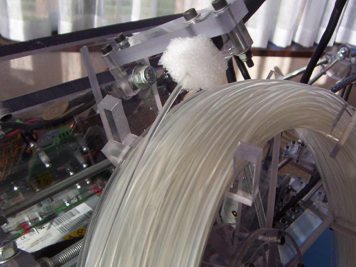
Spool assembly:
A feed supply spool that can hold up to 100 metres of filament has been fitted to the front of the machine on the Mendal frame extension.
The spool being position at the front is to allow easy loading and viewing of filament feeding.
Two ball bearings have been used to allow the spool to rotate freely. This provides smooth resist free feeding of the filament material .
The spool has been mounted in a tilted position. One 6mm diameter bolt has been used to mount the spool against the Mendal frame.
The spool has a 6 spoke assembly. The filament is held with 6 x U shaped pieces. These U shaped pieces have been angled to be parallel to the base of the machine when position at the top of the spool. The overall theory behind all this is to keep the filament better placed on the spool as the filament is feed off. So far this is working very well...
A piece of cable holding wrap with 5 nylon guides allows the filament to be pulled by the extruder motor to the print area. Heat shrink has been used to hold the nylon guides in place. The nylon guides which are barrel shaped have been counter sunk drilled to allow easy threading of the filament to the extruder pinch feed.
A replaceable block of plastic foam is used to keep the filament clean prior to the filament being feed into the cable that takes the filament to the extruder head assembly. The plastic foam has a cut from the central hole that the filament passes thru to the outside edge to allow easy replacement of the plastic foam.
I am planning to make some more spool assemblies to allow quick changing to another filament type (colour or material) Only one hub nut needs to be undone to allow a spool replacement. You don't want to have to unwind a complete spool of filament from the spool and re-wind a different filament every time you wish to print an object with a differnet filament..
X, Y, Z Axis Movement:
The X and Y axis has a full movement of 200mm x 200mm. The Z axis has 110mm movement. Installing a heated bed and the extruder reduced the normal Mendal 140mm Z axis movement.
By replacing 9 threaded rods (currently 390mm long) with longer ones, plus 4 steel guide shafts( x & y axis) as well as replacing the transformer mounting plate with a larger one and extending the stepper motor and sensor wiring; this would allow the design to have a full 140 mm Z axis movement. This is not something I am planning to do at the moment.
Software / firmware :
Reprap Software = Version 20110207 --------------------- Arduino Firmware setup/loading = Version 22
In ( configuration.h ) --------- I selected
#define DEFAULTS MENDEL_MEGA_DEFAULTS
To verife/complile firmware in ( FiveD_GCode_Interpreter ) I had to place- #include "WProgram.h" - before - #include HardwareSerial.h
With using an extruder thermocouple and work around thermocouple bed sensor ( configuration.h ) I de-selected the
#define TEMP_SENSOR TEMP_SENSOR_RRRF100K_THERMISTOR and added
#define TEMP_SENSOR TEMP_SENSOR_AD595_THERMOCOUPLE
I then found that when you verife/complile the firmware that an error occurred missing a “)” on the (Pid) page.
I had to edit -
#if TEMP_SENSOR == TEMP_SENSOR_AD595_THERMOCOUPLE
if(!doingBed) {currentTemperature = ( 5.0 * analogRead(temp_pin* 100.0) / 1024.0;
change this to (temp_pin needs a ')" -
#if TEMP_SENSOR == TEMP_SENSOR_AD595_THERMOCOUPLE
if(!doingBed) {currentTemperature = ( 5.0 * analogRead(temp_pin)* 100.0) / 1024.0;
Also same with the following -
#if BED_TEMP_SENSOR == TEMP_SENSOR_AD595_THERMOCOUPLE
if(doingBed) {currentTemperature = ( 5.0 * analogRead(temp_pin* 100.0) / 1024.0;[/size]
changed this to -
#if BED_TEMP_SENSOR == TEMP_SENSOR_AD595_THERMOCOUPLE
if(doingBed) {currentTemperature = ( 5.0 * analogRead(temp_pin)* 100.0) / 1024.0
A couple of other setups were required to be edited, eg... x,y,z,e steps per mm, invert X & Y direction, stepper board to ADRIAN_POLOLU_STRIPBOARD
I have now been able to test all stepper motor movements (including extruder), home end sensors and control both extruder and bed temperatures using the Arduino Mega 2560 and Reprap 20110207 software. Now printing objects and fine tuning the many parameters options.
Parts sourced from:
Mindkits NZ - Arduino Uno Mega processor Qty1 - Pn# Ard_U_Mega + Breadboard jumper wires Qty 3 - Pn# Jumper_wires
Wattsup NZ - Kapton tape for extruder Qty 1 - Pn# Goldfix/Kapton Tape
Element14 NZ - Thermocoupler amplier IC AD595 Qty1 - Pn# 409194, heated bed 15 ohm resistors Qty 16 - Pn# 1545521, thermal adhesive Qty 1 - Pn# 1211723, PIC processor IC, Dallas 1-temperature sensor, connector plugs Pn# 1761546, 1761538 note: min order is 5 but they can be cut down to make small connectors
Jaycar NZ - Extruder/bed heater driver transistors (TIP122) Qty 2 - Pn# CAT. NO. ZT2292, Thermocouple Type K qty 1 - PN# CAT. NO. QM1283), IC's - DM74LS00 Qty1 Pn# ZS-5000, DM74LS04 Qty1 - Pn#ZS-5004, DM74LS10 Qty1 Pn# ZS-5010, misc resistors, misc capacitors, misc diodes, blank/veraboard pcb's, etchant, misc wire/cables Pn#WH-3009, interior lighting transformer for heated bed Qty 1 - Pn# N16803, power switch Qty - Pn# SK-0985, reset switch Qty 1 - Pn# SP-0716, power socket Qty 1 - Pn# PP-4005. misc connectors, heat shrink, fuse holders, fuses, small screws/nuts, pcb spacers.
Bunnings NZ -Steel 8mm threaded rod + washers + nuts, Stainless steel threaded rods. Washers for 4mm bolts.
Total Trade Supplies NZ - 4mm bolts +nuts, silver steel shafts.
Local engineering shop NZ - Aluminum heated bed plate
Ocean Controls Australia - Stepper motor driver boards - Pn# KTA-261 Qty 1, KTA-262 Qty 1, KTA-263 Qty 1
Small Parts & Bearings Australia - timing belts Qty 2 - Pn# B-MX-532-063-NF, timing pulley Qty 4 - Pn# P-MX-020-063FF-PFR-AHB-06.350, extruder drive gear Qty 1 - Pn# GS48-20-0476B0635-3-HS, bearings qty 4 - Pn# R4-ZZ-ECO, Coupling Qty 2 - Pn#CR-0635-0635-1905-CDG
Makerbot USA - PTFE barrel, Extruder barrel, Nicrome wire, thermocoupler pcb
VXB bearings USA, - Bearings
Obtained from scrapped bits - Polycarbonate sheets, Main power supply, Stepper motors, LED end sensors. Solid state relay
-----------------------------------------------------------------
Cheers Bruce
(Edit: moved thread from NZ-RUG to Mendel Forum, changed thread title to "Kiwi-M5 Mendel Battle Tank!"
--Sebastien)
Edited 22 time(s). Last edit at 03/15/2011 02:35AM by RepRot.


This Reprap based machine has been built with:
- Bullet resistant material.
- Driven with five powerful 24 volt stepper motors.
- Arduino Mega processor controller.
- Power plant consisting of dual power supplies, 563 watt (main supply) and 150 watt (heated bed).
- Massive all-up weight of 25 Kg.
- Long wheel base (Top 2 threaded shafts are 710mm long).
- Loaded and armed with 100 metres of 3 mm diameter filament ammunition.
- Powerful direct drive filament loading stepper motor .
- 0.5 mm diameter howitzer extruder barrel.
- Target area (Print) - X axis 200 mm - Y axis 200 mm - Z axis 110 mm.
This machine now begining field trials for future battles. In other words it's printing and some fine tuning is being carried out.
Having acquired some off-cuts of 10 mm clear polycarbonate sheets, I thought this would be a good material to try and build a Repstrap type of machine.
Polycarbonate is what CD’s and DVD’s are made of. Among other things it is also used for bullet resistant windows.
Polycarbonate is a very strong material, it can be easy cut with a hand saw. It can be machined drilled or cut provided machine cutting speeds are kept low to reduce temperature build up. Screw threads can easy be taped by hand.
Note: Polycarbonate is not normally cut using a laser cutter due to the high level of toxic fumes that is produced, however it can be cut by using a CNC water jet cutter.
Polycarbonate is not a cheap product to buy price is around NZ$460 per square meter for 10 mm thick sheet pieces.
My aim was to build most of the frame parts from the 10 mm Polycarbonate sheets with the least amount of machining. This means some parts will appear to be over engineered.
Due to the complexity of the design, a lot of the work has been, design and build as you go. This has meant some parts have been made and discarded until the design worked. Other designed parts were too hard to machine and a different design part was then made.
The 10 mm polycarbonate worked out well in the end for mounting the standard Mendal axis support bearings.
Trying to mount the 3 guide bearings at 120 degrees with only using 10 mm thick material was going to be difficult, however I found that the bearings being 13 mm diameter could be mounted at 90 degrees to each other, e.g. a bearing could be bolted on the flat surface and then the other bearing could be bolted on the edge using a 4 mm bolt, this then gives each bearing a 1.5 mm exposure on each side of the 10 mm polycarbonate sheet. (See pictures of Y and Z axis).
I also found that the 4mm bolts that hold the 13 mm bearings could be placed in a drill chuck and by using a metal file, the thread could be filed away allowing the bearing to be finely adjusted.
Polycarbonate has a degree of spring tension which can be used keep the ball bearing running against guiding surface.
A lot of the parts were hand cut then machined in a drill mill. A drill mill is a bit like a bench electric drill press. It has a vice that can be moved by hand in X & Y axis direction. The drill chuck is replaced with a tool holder that holds slot drills that can be used to cut and shape the polycarbonate. If you use a drill chuck to hold a slot drill, the sideways force with cutting will cause the drill chuck to fall off the drill shaft.
A mini lathe was used for the odd part - Z axis threaded drive shafts - this was to allow the couplings to be fitted to connect the stepper motors, - Filament spool hub - Filament guides, these are used in the filament spool hose connector that connects to the extruder drive assembly.
Frame:
All of the Mendal frame brackets have been constructed using 2 pieces of machined 10 mm Polycarbonate. This gives a 20 mm thickness for each bracket. The 8 mm threaded shafts nuts then hold these two frame parts together.
The basic Mendal frame design was increased at one end to allow room for two power supplies, (Main power supply and a heated bed transformer).
The additional frame length also allowed room to mount a spool of filament material as well as being able to mount the electronics and power On-Off/Reset switches/LED heater display PCB away from the print area.
Increasing the Mendal frame length has increased the overall rigidity of the frame and added to the all up weight to counter vibrations from the movement of the different moving axis parts.
There are around 150 8 mm diameter Nylock nuts plus washers on this machine. The Nylock nuts were used more for looks. The 8 mm Nylock nuts were a pain to move along the threaded shafts, often I used an electric hand drill turning the threaded shaft and using a spanner to hold the Nylock nuts.
Around 200 4mm diameter bolts of 3 different lengths (plus some nuts and washers) have also been used. Some of the longer 4 mm bolts sourced didn't have thread along their entire length. I used a 4 mm die to increase the length of thread. This was relatively easy as the bolts already had thread to start with.
Power supplies:
The mains power (230 Volt AC) is connected to the machine via a cable lead plug-able power socket. Power is then feed to a power switch which is fitted to the front of the machine. the switched power is then feed onto the two power supplies.
An earth mains power connection from the main power supply is connection to the Mendal frame. All 8 mm threaded shafts of the machine are bonded together to reduce EMF interference. To bond the 8 mm threaded shafts, a wire has been placed under the 8 mm nuts at frame junction points to connect all the 8 mm threaded shafts together.
A 563 watt power unit that outputs +5 volts, +12 volts and +24 volts has been used as the main machines power supply. All three voltage outputs go to a housing which contains 3 fuses to provide additional protection in the event of a electrical short circuit.
The main (+5v, +12v, +24v) power supply which has an internal cooling fan has been mounted to direct the air flow away from the print bed area. A exhaust duct has been installed to enable piping of fumes from the machine environment (Currently using a household vacuum cleaner hose).
A 150 watt interior lighting transformer (240 volt AC to 12 volt AC) has been used for the supply power for the heated bed. A 20 amp solid state (230 volt AC) relay is used to switch the output of the transformer (12 Volt AC) to the heated bed heater resistors 15 ohm 10W).
Headed Bed:
The heated bed is a 200 mm x 200 mm - 4 mm thick aluminum plate fitted with 16 (15 Ohm 10 watt) power resistors. The 16 (15 ohm) resistors plus a sensor have been glued with thermal glue (Fisher Elektronik WLK5 Adhesive rated at 150C ). A Dallas one-wire digital sensor (uses 2 wires) is used to digitally monitor the bed plate temperature.
I had previously built this heated bed for a Darwin machine which had a separate PIC based controller. As I had run out of thermal glue and this glue is not cheap, I have used a PIC Microchip processor, programmed to convert the digital temperature from the Dallas one wire digital sensor reading to a DC signal that matches a thermocouple output. This DC output signal is for the machine Aduino Mega processor to monitor and control the temperature of the heated bed. I am planning to reprogram the Aduino Mega processor firmware to accept one-wire input from the heated bed sensor sometime in the future and this will allow the removal of the PIC processor work around.
The aluminum heated bed plate is positioned 6 mm off the Y axis polycarbonate plate with four screws and four PTFE spacers located at the bed plate corners. The Y axis polycarbonate plate that supports the heated bed, has been cut out in the middle to give clearance for the bed heater resistors and to provide air flow to stop the surrounding polycarbonate from heating up and wrapping. Three of the heated bed plate mounting holes on the Y axis polycarbonate plate have been slotted to allow thermal expansion of the heated bed.
Warm up time for the heated bed to go from 20˚C to 55˚ C takes approx 3 minutes and 15 seconds, about the same time as the extrude heater takes to reach 190 ˚ C.
Stepper Motors:
Five 24 volt stepper motors have been used. (4 small and 1 large) 1 - X axis, 1 - Y axis, 2 - Z axis, 1 - Extruder.
I obtained these stepper motors from a scrapped automatic cash machine (ATM). The large stepper motor used for the extruder is the motor that feeds your requested money to you.
Two direct drive stepper motors have been used for the Z axis. Each of these stepper motors have their own LED home sensors as well as separate stepper driver boards. An additional PCB is used to allow these two Z stepper motors to auto synchronize when being sent to their home position. Basically the stepper motor driver boards don’t receive step pulses from the Arduino mega processor if the LED home sensor is blocked when the motor is being driven in a backwards direction towards the home sensor. The Z axis home signal is only sent to the processor when both Z axis LED home sensors are blocked.
This hardware feature also stops the processor ramming the extruder heater barrel into the bed plate should the processor ignore the LED sensor signal for any reason. The auto synchronize PCB circuit has been designed for the Z axis LED home sensor signals to be 0 volts (e.g. driven to 0 volts) when sensor is blocked e.g. axis is at home position. [For circuit design, refer to the schematic picture...]
All stepper motors cables (2 sets of twisted pairs) have an un-insulated wire that has been wrapped with tin foil and covered with heat shrink. This wire is also connected to the stepper motor base and the other end of this wire is connected to a 8 mm threaded shaft (being frame ground). This provides shielding of the machines electronics from EMF interference.
I found that mounting the Z stepper motors facing upwards (e.g. output shaft upwards) that the output shaft bearings were spring loaded. This could change the position of the Z axis, subject to the supported weight. (This only occurs with some types of stepper motors). The stepper motor bearing springs were replaced with fixed washers to keep an accurate Z axis position.
The large extruder stepper motor is rated at 24 volts and 3.5 amps. This is being driven with 24 volts from the stepper driver PCB which is rated at 2.5 amps. As the stepper driver PCB's I am using are current protected, this hasn't caused any issues.
X Y Z Axis: The X Y Z axis are all guided with standard 13 mm diameter Mendal ball bearings at 90 degree angles.
12 bearing were used for the X axis.
10 bearing were used for the Y axis.
10 bearing were used for the Z axis.
2 larger bearings that allow the use of ¼” shafts were used to on the X axis drive belt (opposite end to stepper motor.
2 larger bearings that allow the use of ¼” shafts were used to on the Y axis drive belt (opposite end to stepper motor).
Using the larger bearings allowed the same timming belt pulleys to be used at both ends of the drive belt. (Same type pulley as used on stepping motors).
The Z axis threaded drive shafts lift nuts are designed to self align. Basically they are allow to move back and forth and left and right but not to rotate. This is to reduce any binding with misalignment of the Z drive shafts/stepping motors. I have replaced the metal lifting nuts with nuts I have made from a synthetic plastic material. This reduces noise as well as wear on the threaded shafts. Wear to the synthetic nuts will not be a problem as the machine will self adjust when homing the Z axis.
The X axis stepping motor has been mounted on its side to reduce the use of multiple bearings. A single continuous drive belt is used to move the extruder. Belt tension can be adjusted by moving the complete stepping motor assembly or adjusting the belt holding clamps on the extruder.
The Y axis stepping motor is mounted on the inside of the Mendal frame. Belt tension can be adjusted by moving the stepping motor.
Electronics:
The electronics circuits are located on the back of the Mendal frame in an enclosed polycarbonate box.
The polycarbonate box assembly is enclosed except for an opening along the bottom edge to allow electrical cabling and an upwards air flow. There is also a hole towards the top of the enclosure to allow a 12 volt cooling fan to provide air movement from the electronics enclosure box. The 12 volt PC CPU fan is connected to the +5 volt supply to provide a slow and quiet air flow.
An Ardiuno Mega 2560 processor controls the machine. Breadboard jumpers have been used to connect signals from the processor to the driver PCB's.
Ardiuno Mega 2560 processor signals ***
- Reset signals - Reset (1 x input).
- Extruder heater PCB signal - Heat (1 x output) & Temperature (1 x input).
- Heated Bed PCB signals - Heat (1 x output) & Temperature (1 x input).
- Stepper motor PCB signals (3 axis & extuder) - enable/step/direction (3 x outputs for each stepper motor - 12 outputs for 3 axis + extruder).
- Stepper motor home sensor PCB signals (3 axis signals) - Home (3 x input3).
Total processor signals 20. (inputs = 6, outputs = 14).
Note: Z Axis signals goes to the auto synchronize PCB which drives 2 stepper PCB's -refer back to section about stepper motors.
Some of the purchased jumpers needed to lengthened. (I used heat shrink when joining additions to these jumper wires).
Previously I was using a sanguino processor, with upgrading this to an Arduino Mega, and the fact that the The Arduino Mega +12 volt power plug also sticks out with the USB plug, I decided the best way around this was to extended the USB cable conection socket rather than having a USB cable hanging out of the machine. This required a USB connector socket being mounted on a PCB (vera board at present) that is then screwed to the electronics box. A USB cable on this PCB then feeds the USB signals to the Arduino Mega.
The Arduino Mega 2560 processor is connected to the +12 volt reprap power supply (far better that running off USB supply or +5 volt reprap supply - This reduces voltage drop that can occur with longer wiring and interference issues). If no +12 volt is present (e.g. reprap is turned off) the Arduino Mega 2560 board will run from the USB power. This allows the firmware to be loaded with the Reprap machine turned off.
Comparing the Sanguino processor with the new Arduino Mega 2560. There has been no issues (or pain) with having to press the reset switch at the right time before uploading firmware. You just simply just select upload and the firmware uploads....
I found it was good to be able to monitor both the extruder and bed heater power signals when using the Reprap. The extruder and bed heater driver PCB has LED's for this, but as the electronics box is located at the back of the machine, these LED's are not visable from the front of the machine. I fitted a couple of LED's on a small PCB on the front power/ reset switch panel and ran 2 wires to the solid state relay and one wire to the extruder connector on the heater driver PCB..
- Having an extruder and bed heater power LED's visable gives a good indication whether extruder/bed is up to temperature (eg. flashing) and things are running correctly without having to monitor the PC screen. It also would show if a smoke condition accured whether it was being caused by continous power being supplied to a heater. eg. Driver transistor shorted. KiwiM5-k.jpg
PCB’s contained within the electronic enclosure:
- Custom build sensor and Z axis PCB. (Controls the two Z stepper motor signals and allows for auto synchronize of the two Z stepper motors).
- Ardiuno Mega 2560 processor PCB.
- Customer heater driver PCB. (Extruder and heated bed, note: heated bed driver signal goes to a solid state relay).
The extruder and heated bed temperature sensor signals also pass thru this PCB.
- Six stepper driver PCB’s (One spare stepper driver. Currently the output is not wired up - Future gear pump paste extrude).
Design features: -------------------
- Having the electronics components enclosed allows for greater protection from un-authorization contact with items that may short circuit components.
- The enclosure cover stops the Arduino Mega processor connector header pins (breadboard jumper pins) from falling out.
- Modular construction – separated PCB’s allows quick trouble shooting and cheaper exchange parts replacement.
- A barrier support has been fitted below the heater PCB to stop solder or parts dropping directly onto stepper driver PCB’s should a fault occur that results in a melt down.
- A reset switch has been fitted to the front of the machine alongside the mains power switch.
- Electrical cables have been wrapped in Tessa woven fabric tape. (Designed for bundling cables rather that just insulation. - Don't think you can buy it in NZ).
Warning: Something I found out the expensive way when I destroyed one stepper motor PCB. -
The stepper motor control PCB's have warnings about correct polarity of the supply voltage (in my case +24 volt). You are also advised that the driver PCB's are current protected. You are also warned not to connect or disconnect the stepper motor connections with power on. What you are not told is that each motor controller has a 4 pin plug output connector to the stepper motor. The 2 middle ones are for one set of motor coils and the outer 2 are for the other set of motor coils.
You need to take extreme care with wiring of stepper motors as if you end up wiring one set of the stepper motor coils to the controller inner connection and one to the outer connection and same with the other stepper motor coil set, the over current protection and thermal protection won’t save you and the controller will go snap, crackle, smoke!!! By-By-Stepper Driver…. .... You don’t get a second chance!!! ... Same properly applies with other types of stepper motor driver PCB's.
Best to wire one stepper motor driver PCB up, check the wiring, then re-check and then re-check again and then connect power and test with software. If all works correctly proceed with wiring and testing the next stepper motor driver PCB, and so on ...
If stepper motor home sensors are no configured correctly in the firmware or wrong type used, you may not be able to get the movements that you think you should when testing. If the processor thinks the stepper motor is already at home position it will only allow you to move in a forward direction. Also its easy to wire up a stepper motor to have the motor running backwards. This is not a major issue as you just need to change the polarity around for one of the paired sets of coil winding for the stepper motor. Again you need to tripple check that the above warning is followed or snap, crackle, smoke!!! .
Extruder Assembly:
A powerful direct drive extruder stepper motor has been used with a Makerbot PTFE and 0.5mm barrel. For the extruder stepper motor to feed the filament, I used a 20 tooth drive gear that I purchased from Small Parts & Bearings Australia PN# GS48-20-0476B0635-3-HS. I filed the teeth of the gear to a sharp point to better grip the filament material. I also used two 13mm bearings bolted together with a M4 bolt on an adjustable spring loaded arm that can be adjusted to provide pressure to hold the filament against the feed gear.
For control of the extruder temperature a thermocoupler has been fitted to the extruder barrel. To stop electricial interference affecting the extruder temperature readings, a thermocoupler PCB interface has been mounted at the extruder assembly close to the thermocouple.
The use of a large extruder stepper motor and a large extruder area has been designed to allow future redesign and experimental work. Future plan is to try 0.3mm custom built extruder barrels and also selectable multiple colour filaments by using just one extruder motor, e.g. different filament pinch wheels that can be engaged as required to feed different colour filament.
Spool assembly:
A feed supply spool that can hold up to 100 metres of filament has been fitted to the front of the machine on the Mendal frame extension.
The spool being position at the front is to allow easy loading and viewing of filament feeding.
Two ball bearings have been used to allow the spool to rotate freely. This provides smooth resist free feeding of the filament material .
The spool has been mounted in a tilted position. One 6mm diameter bolt has been used to mount the spool against the Mendal frame.
The spool has a 6 spoke assembly. The filament is held with 6 x U shaped pieces. These U shaped pieces have been angled to be parallel to the base of the machine when position at the top of the spool. The overall theory behind all this is to keep the filament better placed on the spool as the filament is feed off. So far this is working very well...
A piece of cable holding wrap with 5 nylon guides allows the filament to be pulled by the extruder motor to the print area. Heat shrink has been used to hold the nylon guides in place. The nylon guides which are barrel shaped have been counter sunk drilled to allow easy threading of the filament to the extruder pinch feed.
A replaceable block of plastic foam is used to keep the filament clean prior to the filament being feed into the cable that takes the filament to the extruder head assembly. The plastic foam has a cut from the central hole that the filament passes thru to the outside edge to allow easy replacement of the plastic foam.
I am planning to make some more spool assemblies to allow quick changing to another filament type (colour or material) Only one hub nut needs to be undone to allow a spool replacement. You don't want to have to unwind a complete spool of filament from the spool and re-wind a different filament every time you wish to print an object with a differnet filament..
X, Y, Z Axis Movement:
The X and Y axis has a full movement of 200mm x 200mm. The Z axis has 110mm movement. Installing a heated bed and the extruder reduced the normal Mendal 140mm Z axis movement.
By replacing 9 threaded rods (currently 390mm long) with longer ones, plus 4 steel guide shafts( x & y axis) as well as replacing the transformer mounting plate with a larger one and extending the stepper motor and sensor wiring; this would allow the design to have a full 140 mm Z axis movement. This is not something I am planning to do at the moment.
Software / firmware :
Reprap Software = Version 20110207 --------------------- Arduino Firmware setup/loading = Version 22
In ( configuration.h ) --------- I selected
#define DEFAULTS MENDEL_MEGA_DEFAULTS
To verife/complile firmware in ( FiveD_GCode_Interpreter ) I had to place- #include "WProgram.h" - before - #include HardwareSerial.h
With using an extruder thermocouple and work around thermocouple bed sensor ( configuration.h ) I de-selected the
#define TEMP_SENSOR TEMP_SENSOR_RRRF100K_THERMISTOR and added
#define TEMP_SENSOR TEMP_SENSOR_AD595_THERMOCOUPLE
I then found that when you verife/complile the firmware that an error occurred missing a “)” on the (Pid) page.
I had to edit -
#if TEMP_SENSOR == TEMP_SENSOR_AD595_THERMOCOUPLE
if(!doingBed) {currentTemperature = ( 5.0 * analogRead(temp_pin* 100.0) / 1024.0;
change this to (temp_pin needs a ')" -
#if TEMP_SENSOR == TEMP_SENSOR_AD595_THERMOCOUPLE
if(!doingBed) {currentTemperature = ( 5.0 * analogRead(temp_pin)* 100.0) / 1024.0;
Also same with the following -
#if BED_TEMP_SENSOR == TEMP_SENSOR_AD595_THERMOCOUPLE
if(doingBed) {currentTemperature = ( 5.0 * analogRead(temp_pin* 100.0) / 1024.0;[/size]
changed this to -
#if BED_TEMP_SENSOR == TEMP_SENSOR_AD595_THERMOCOUPLE
if(doingBed) {currentTemperature = ( 5.0 * analogRead(temp_pin)* 100.0) / 1024.0
A couple of other setups were required to be edited, eg... x,y,z,e steps per mm, invert X & Y direction, stepper board to ADRIAN_POLOLU_STRIPBOARD
I have now been able to test all stepper motor movements (including extruder), home end sensors and control both extruder and bed temperatures using the Arduino Mega 2560 and Reprap 20110207 software. Now printing objects and fine tuning the many parameters options.
Parts sourced from:
Mindkits NZ - Arduino Uno Mega processor Qty1 - Pn# Ard_U_Mega + Breadboard jumper wires Qty 3 - Pn# Jumper_wires
Wattsup NZ - Kapton tape for extruder Qty 1 - Pn# Goldfix/Kapton Tape
Element14 NZ - Thermocoupler amplier IC AD595 Qty1 - Pn# 409194, heated bed 15 ohm resistors Qty 16 - Pn# 1545521, thermal adhesive Qty 1 - Pn# 1211723, PIC processor IC, Dallas 1-temperature sensor, connector plugs Pn# 1761546, 1761538 note: min order is 5 but they can be cut down to make small connectors
Jaycar NZ - Extruder/bed heater driver transistors (TIP122) Qty 2 - Pn# CAT. NO. ZT2292, Thermocouple Type K qty 1 - PN# CAT. NO. QM1283), IC's - DM74LS00 Qty1 Pn# ZS-5000, DM74LS04 Qty1 - Pn#ZS-5004, DM74LS10 Qty1 Pn# ZS-5010, misc resistors, misc capacitors, misc diodes, blank/veraboard pcb's, etchant, misc wire/cables Pn#WH-3009, interior lighting transformer for heated bed Qty 1 - Pn# N16803, power switch Qty - Pn# SK-0985, reset switch Qty 1 - Pn# SP-0716, power socket Qty 1 - Pn# PP-4005. misc connectors, heat shrink, fuse holders, fuses, small screws/nuts, pcb spacers.
Bunnings NZ -Steel 8mm threaded rod + washers + nuts, Stainless steel threaded rods. Washers for 4mm bolts.
Total Trade Supplies NZ - 4mm bolts +nuts, silver steel shafts.
Local engineering shop NZ - Aluminum heated bed plate
Ocean Controls Australia - Stepper motor driver boards - Pn# KTA-261 Qty 1, KTA-262 Qty 1, KTA-263 Qty 1
Small Parts & Bearings Australia - timing belts Qty 2 - Pn# B-MX-532-063-NF, timing pulley Qty 4 - Pn# P-MX-020-063FF-PFR-AHB-06.350, extruder drive gear Qty 1 - Pn# GS48-20-0476B0635-3-HS, bearings qty 4 - Pn# R4-ZZ-ECO, Coupling Qty 2 - Pn#CR-0635-0635-1905-CDG
Makerbot USA - PTFE barrel, Extruder barrel, Nicrome wire, thermocoupler pcb
VXB bearings USA, - Bearings
Obtained from scrapped bits - Polycarbonate sheets, Main power supply, Stepper motors, LED end sensors. Solid state relay
-----------------------------------------------------------------
Cheers Bruce
(Edit: moved thread from NZ-RUG to Mendel Forum, changed thread title to "Kiwi-M5 Mendel Battle Tank!"
--Sebastien)
Edited 22 time(s). Last edit at 03/15/2011 02:35AM by RepRot.
|
Re: Rotorua Reprap January 06, 2011 05:59PM |
Registered: 16 years ago Posts: 91 |

|
Re: Rotorua Reprap January 06, 2011 10:38PM |
Admin Registered: 17 years ago Posts: 1,791 |
It's beeeeeeaaauuutiful. Nice bit of work, RepRot. 
(Make repraps, not war, man!)
-Sebastien, RepRap.org library gnome.
Remember, you're all RepRap developers (once you've joined the super-secret developer mailing list), and the wiki, RepRap.org, [reprap.org] is for everyone and everything!
(Make repraps, not war, man!)
-Sebastien, RepRap.org library gnome.
Remember, you're all RepRap developers (once you've joined the super-secret developer mailing list), and the wiki, RepRap.org, [reprap.org] is for everyone and everything!
|
Re: Rotorua Reprap January 10, 2011 06:58PM |
Registered: 13 years ago Posts: 248 |

|
Re: Rotorua RepRap January 11, 2011 01:23AM |
Admin Registered: 17 years ago Posts: 1,791 |
Once I sort out the upgrade to the electronics I will be looking at adding it to a wiki page.
Too late, it's official documentation now! Muahahaha!
btw way, don't forget to join the reprap-dev mailing list:
[reprap.org]
the technical-but-friendly mailing list for all you technical-but-friendly people out there.
Too late, it's official documentation now! Muahahaha!
btw way, don't forget to join the reprap-dev mailing list:
[reprap.org]
the technical-but-friendly mailing list for all you technical-but-friendly people out there.
|
Re: Rotorua RepRap January 11, 2011 03:02AM |
Registered: 14 years ago Posts: 128 |
|
Re: Rotorua RepRap January 11, 2011 03:43AM |
Admin Registered: 17 years ago Posts: 1,791 |
Oops.
Forgot link:
http://reprap.org/wiki/Kiwi-M5_Mendel_Battle_Tank
-Sebastien, RepRap.org library gnome.
Remember, you're all RepRap developers (once you've joined the super-secret developer mailing list), and the wiki, RepRap.org, [reprap.org] is for everyone and everything!
Forgot link:
http://reprap.org/wiki/Kiwi-M5_Mendel_Battle_Tank -Sebastien, RepRap.org library gnome.
Remember, you're all RepRap developers (once you've joined the super-secret developer mailing list), and the wiki, RepRap.org, [reprap.org] is for everyone and everything!
|
Re: Rotorua RepRap March 12, 2011 01:01AM |
Admin Registered: 17 years ago Posts: 1,791 |
Bruce,
I've moved this thread from the NZ-RUG forum to the Mendel forum, since that's the best place for it.
-Sebastien
-Sebastien, RepRap.org library gnome.
Remember, you're all RepRap developers (once you've joined the super-secret developer mailing list), and the wiki, RepRap.org, [reprap.org] is for everyone and everything!
Sorry, only registered users may post in this forum.