[Watson] Frame: CNC Aluminum Plates, 2:1 Pulleys, Sync'd Z-Axes
Posted by JazzyMT
|
[Watson] Frame: CNC Aluminum Plates, 2:1 Pulleys, Sync'd Z-Axes August 19, 2012 09:40PM |
Registered: 12 years ago Posts: 52 |
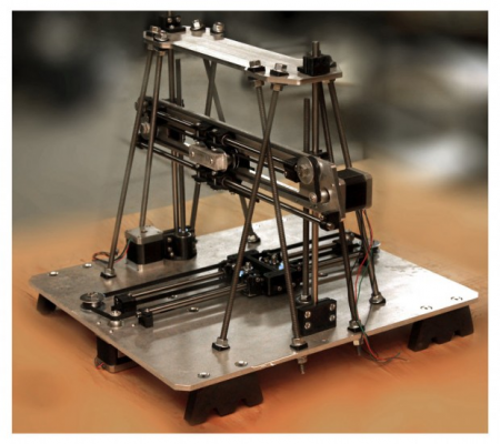
I'm so close I can almost taste it! Ok, so there's still a lot of work to do, but I thought I would share my current progress on the Watson frame since it's starting to look like a real printer. It also provides an opportunity to talk about some of the unique design elements that sets the Watson frame apart.
Plate-Mounting
One of the earliest concepts that drove the design on the Watson frame was the idea that many components share a common plane and should therefore (in my opinion) share a common mounting reference. Rather than assembling disparate sub-assemblies with rods and such which causes additional alignment issues - I tried to relate all parts in a given axis to a single plate. This should provide several specific advantages over alternate construction ideologies:
High Stiffness - In my experience the quality of a print depends largely on the ability of a printer frame to cope with the forces induced by its own movements and attenuate the resulting vibrations. One of the biggest factors in controlling those vibrations is the stiffness of the frame. The stiffness of the printer as a whole depends on several components and connections and is still a work in progress, but the stiffness of each axis seemed like a good place to start. Using a single plate to mount all the components of an axis practically eliminates the possibility of independent movement between those parts. This is most evident in the pulley system because for example the motor cannot deflect relative to any of the pulleys. This means you can preload the belt with sufficiently high tension and you will not experience changes in tension or position during operation.
Precision Alignment - Although the intent is for these plates to be machined on a CNC mill, they could also be manufactured with care and precision using "old-school" layout techniques and rudimentary tools. Either way - features in these plates should have relatively high precision which can be used to locate all other moving parts on an axis - providing an extremely simple & reliable common reference. This precise common locating also means the axis will resist skewing - so the distance between rods and alignment to the pulley system will be very good and the X-axis will maintain good perpendicularity to the Z-axis without any special measurement or corrections necessary.
Reduced Complexity - Complexity isn't an intrinsically "bad" thing, but it can increase cost and reduce reliability. Since I also wanted to incorporate a non-reversing 2:1 pulley system though, finding ways to reduce complexity was important. Using just one part to mount all the pulleys, motor and (with simple stand-offs) bearing rods & end-stop sure helps. The X-axis also mounts the Z-axis bearings and lead screw nut to the same common plate.
Non-Reversing 2:1 Pulley System
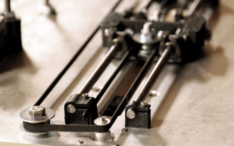
There are other 2:1 pulley systems already showing good promise in the open source community. Their implementations demonstrate improved printer performance, but some of them compromise on reliability by using a reversing belt path. The Watson X & Y carriage belts never experience more than 180 degrees of flexure - similar to most other standard 1:1 pulley systems. It would be much easier to use a reversing belt path, but that requires the belt to flex 180 degrees in both directions - or 360 degrees of total flexure in what's called "fully reversed bending"- severely increasing the fatigue stress and potential for early belt failures.
Watson X-Axis Front
The simplicity of the plate-mounted system also makes assembly and maintenance easy. During assembly - to tension the belt all you have to do is grab it with some needle nose pliers and rotate the pliers next to the clamp block much like a tuning peg on a violin. You can easily obtain as much tension as you need this way and then simply screw in the clamp on the neighboring block and you're done. The stiffness of the pulley system and strength of the component parts means you can achive good tension without worrying about overstressing the frame too.
Watson X-Axis Back
A 2:1 system may be overkill - it might be unnecessary and it probably has other drawbacks that aren't well understood yet because there are few of them in use at this time. However the increase in mechanical advantage (coupled with a fine belt and small metal drive pulley) and reduction in reflected inertia could have several practical advantages in achieving fine motion control and hopefully - high speeds. One of the most critical things to evaluate on this prototype will be the overall effectiveness of this pulley system and vetting it for prime time in the final production design.
Common Z-axis Motion
You may or may not have had the pleasure of using a printer with two Z-axis motors, but I have and it was important to me that the Watson printer did not share that design flaw. In industrial designs - two motors that need to move synchronously would never be allowed to run in open loop control (no feedback) - especially if synchronization is critical. The reason for that immediately becomes clear the first time one motor moves and the other doesn't - and insult is added to injury when you realize it has enough torque and mechanical advantage to tear your printer apart.
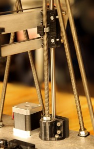
The Watson printer frame uses two Z-axis screws, but they are tied together with pinned pulleys and a single continuous belt. The Z-axis bearing mounts are so stiff the second screw isn't really needed for strength - it will move smoothly up and down on a single screw, but I get warm fuzzies knowing it's supported at both ends with mechanically synchronized motion. The 2 screws and pinned timing pulleys also allows us to lock in a perfect horizontal alignment without worrying about later loosing that alignment and having to recalibrate the machine.
Additionally both Z-axis screws are mounted on a pair of preloaded ball bearings that ensure straight, wobble-free actuation. The dual bearings accommodate belt tension and applied torque without allowing the shaft to flex. This configuration also prevents the screws from shifting vertically - maintaining horizontal alignment to each other at all times. The mounting block also locates the z-axis bearing shafts ensuring correct spacing and parallelism.
The Z-axis motor shares the same plate as the Y-axis and the slots machined in the plate allow tensioning of the belt - eliminating the need for an additional tensioner pulley.
Testing the Prototype
Over a decade of industry experience has taught us not to take anything for granted. So far the assembly process has gone pretty well and I'm really impressed with how most of it looks and feels, but there's plenty of testing and verification to do. We really want anyone using our printer to come away with a very positive experience so there's a lot to consider aside from just performance like ease of use, maintenance, noise, and reliability. Moving forward we are also certainly eager to hear the community's feedback in any improvements for a final design.
Keep in mind that this design is a prototype. Its purpose is to test key mechanical features and demonstrate proof of concept with simple manufacturing techniques. The final design will most likely add sheet-metal and/or additional plates and eliminate any threaded rods in the structural components so it could look significantly different, but the foundation of a good design is what's important.
Our site is a bit rough still, but you can follow our progress on the design here:
[] www.apparentlyconnected.com []
Our electronics package was also posted on the forums here:
[Watson] Electronics: DSP/DSC, Allegro 4988, Dual Extruder, Bed Control, User Interface Port
Thanks!
Edited 1 time(s). Last edit at 08/19/2012 11:00PM by JazzyMT.
|
Re: [Watson] Frame: CNC Aluminum Plates, 2:1 Pulleys, Sync'd Z-Axes August 19, 2012 10:35PM |
Admin Registered: 15 years ago Posts: 1,470 |
That looks nice and quite rock-solid. What length of travel do you get out of the axes?
|
Help improve the RepRap wiki!
Just click "Edit" in the top-right corner of the page and start typing. Anyone can edit the wiki! |
|
Re: [Watson] Frame: CNC Aluminum Plates, 2:1 Pulleys, Sync'd Z-Axes August 19, 2012 10:54PM |
Registered: 12 years ago Posts: 52 |
The prototype is matched to the MK2 heat bed so it's 210 x 210 x 150mm (8.4 x 8.4 x 6.0 in).
The final design parameters will depend on testing and feedback. It might not change and/or may offer it in multiple sizes, but the original plan was for a larger 300 x 300 x 200mm envelope (12 x 12 x 8 in).
Do you think people would want a larger envelope?
The final design parameters will depend on testing and feedback. It might not change and/or may offer it in multiple sizes, but the original plan was for a larger 300 x 300 x 200mm envelope (12 x 12 x 8 in).
Do you think people would want a larger envelope?
|
Re: [Watson] Frame: CNC Aluminum Plates, 2:1 Pulleys, Sync'd Z-Axes August 19, 2012 11:40PM |
Admin Registered: 15 years ago Posts: 1,470 |
JazzyMT Wrote:
-------------------------------------------------------
> The prototype is matched to the MK2 heat bed so
> it's 210 x 210 x 150mm (8.4 x 8.4 x 6.0 in).
>
> The final design parameters will depend on testing
> and feedback. It might not change and/or may
> offer it in multiple sizes, but the original plan
> was for a larger 300 x 300 x 200mm envelope (12 x
> 12 x 8 in).
>
> Do you think people would want a larger envelope?
Some people will want a larger envelope. I built a MendelMax with a 300 x 300 x 200mm build area. It's nice, but not necessary for most prints. It also takes up a ridiculous amount of desk space. I will probably be building a much smaller printer in the future to go along with it, as 95% of the stuff I print will fit just fine on a 200 x 200 bed. That said, the large bed is nice for printing many parts at once, I can fill up the print bed with parts and let it print overnight.
I think the majority of people will be happy with a Mendel-sized build area. Having a larger printer option is always nice though.
|
Help improve the RepRap wiki!
Just click "Edit" in the top-right corner of the page and start typing. Anyone can edit the wiki! |
|
Re: [Watson] Frame: CNC Aluminum Plates, 2:1 Pulleys, Sync'd Z-Axes August 20, 2012 02:25AM |
Admin Registered: 16 years ago Posts: 13,888 |
... I'm intersted, when someone will build an 'upside-down' printer, fixed to the ceiling, so the building bed will be only lowering when printing.
If idle, it will simply 'vanish' ... maybe with some camouflage or nice images on the bottom, so it will represent a piece of 'living art' in the living room ...
Viktor
--------
Aufruf zum Projekt "Müll-freie Meere" - [reprap.org] -- Deutsche Facebook-Gruppe - [www.facebook.com]
Call for the project "garbage-free seas" - [reprap.org]
|
Re: [Watson] Frame: CNC Aluminum Plates, 2:1 Pulleys, Sync'd Z-Axes May 16, 2013 07:55PM |
Admin Registered: 11 years ago Posts: 3,096 |
|
Re: [Watson] Frame: CNC Aluminum Plates, 2:1 Pulleys, Sync'd Z-Axes May 16, 2013 08:41PM |
Registered: 10 years ago Posts: 474 |
Sorry, only registered users may post in this forum.


