Millennium Peregrine – High Speed Large Format 3D Printer Project - Detailed Build Diary
Posted by CinciCliff
|
Millennium Peregrine – High Speed Large Format 3D Printer Project - Detailed Build Diary March 21, 2018 09:08PM |
Registered: 6 years ago Posts: 26 |

The Millennium Peregrine is a high speed large format development project intended to understand the process performance limits of Fused Filament Fabrication (FFF) 3D printers and to create a new machine capable of printing large high resolution objects in a reasonable amount of time. This project is just beginning – preliminary calculations look promising, we have started some preliminary testing, and we have enjoyed a few beers while formulating a plan. We invite you to join us on this adventure and hope we can create something extraordinary together.
Preliminary Build Targets
FFF – Fused Filament Fabrication Technology
Open Source Design
Build Volume: 24 X 24 X 24 inch (610 X 610 X 610 mm)
Heated Enclosed Temperature Controlled Oven (Min Up to 110C / 230 F - Stretch Up to 225C / 437F)
All components inside oven capable of withstanding high temperatures or actively cooled
Mechanics:
Print Velocity: 1000 mm/s
Print Acceleration: 30000 mm/s^2
3 Axis X-Y-Z Cartesian Gantry
Part Stationary or Only Moving in Vertical Z Direction
Motion by Lead Screws or Ball Screws
Extruders:
Dual Extruders to Enable Soluble Support Structure
Filament Fed from Standard 1.75 or 2.85 mm Filament
Flow Rate: 576 cm^3/hr 0.6 kg/hr
Filament Feed Rate: 66.5 mm/s
Supports Standard E3D V6 Style 0.4 mm Nozzle
Print Materials: ABS, PLA, ASA, Nylon 12, Polycarbonate, Ultem, Peek, etc
Controls:
Control System – 32 Bit
Motors – NEMA 23 Stepper Motors
Stepper Drives – External Drives - High Voltage (80VDC)
Frame:
High Rigidity 40 X 40 mm Aluminum Extrusions or Laser Cut Steel
Insulated Double Wall
Insulated panels removable to allow machine to fit through a standard residential doorway
This is an after hours hobby build by a small team of engineers and scientists from Cincinnati, OH USA. We want to learn more about 3D printing and build something cool. We would like to understand the process limitations of Fused Filament Fabrication (FFF) 3D printers to maximize performance. We plan to take some risk and hope to push the envelope for performance. We plan to share our learnings with the community and hope we can be helpful to others. So even if this never works or stalls out we will all learn something. This is not going to be a budget build, but we are trying to make choices with potential to be reduced in cost with scale or further refinement. If the printer proves useful, we plan to take some steps to reduce costs and provide better documentation.
The name Millennium Peregrine refers to our 1,000 mm/s print velocity goal and pays homage to a fast fictional space craft and the world’s fastest animal the Peregrine Falcon.
We thought that creating a build diary on the reprap.org Forum might be a nice way to foster interaction and discussion during development vs the wiki format. We hope you find this interesting and look forward to some thought-provoking conversation. Please share your suggestions, cautions, and questions.
Edited 1 time(s). Last edit at 03/22/2018 08:35AM by CinciCliff.
|
Re: Millennium Peregrine – High Speed Large Format 3D Printer Project - Detailed Build Diary March 21, 2018 09:14PM |
Registered: 6 years ago Posts: 26 |
Why We Want to Explore High Print Velocity and High Dynamic Performance
It would be useful to print large parts such as custom automotive parts, full size Halloween costumes, toys, sculptures, etc achieving an attractive surface finish and fine detail.
We initially were planning to build a large format printer with comparable performance with our PRUSA i3 MK2S and TAZ 5 printers. We approximated print times using Repetier for 3 large example parts using 0.200 mm layer height and 0.5 mm nozzle. At 30 mm/sec print speeds the parts were predicted to take incredibly long to print 4.5 – 24 days of continuous printing! This time could be decreased by increasing the layer height and nozzle size. This would require an undesirable trade off in surface finish and detail.
The Repetier approximation suggests that increasing print speed to 1000 mm/s can dramatically reduced predicted print time to less than one day. (We recognize that these time approximations are very rough but logically we do think there is some time to save by printing at higher velocities.)
Example Part ------- Dimensions (inches) -- ABS Usage (kg) -- Print Time @ 30 mm/s -- Print Time @ 1000 mm/s
Air Duct -------------- 24 X 32 X 32 ------------- 7.2 ---------------------- 581 hours ---------------------- 18 hours
Costume Shield ---- 24 X 32 X 3 -------------- 1.5 ---------------------- 108 hours ---------------------- 4 hours
Eiffel Tower --------- 16 X 16 X 36 ------------- 2.9 ---------------------- 229 hours ---------------------- 17 hours
To achieve high print velocities, the system must accelerate the print head up to speed in a reasonable distance. Typical RepRap printers are set to 5,000 mm/s^2 in the Marlin firmware. This is roughly 0.5 g of acceleration. At an accel rate of 5,000 mm/s^2, it will take 100 mm of travel to achieve 1,000 mm/s. At an accel rate of 30,000 mm/s^2 (3 g’s), it will take 16.7 mm of travel to achieve 1,000 mm/s. Care must be taken in mechatronic system design to minimize mass / inertia and to insure adequate system stiffness to achieve desired accuracy.
The initial focus of our project is to explore feasibility of printing at very high print speeds with high dynamic performance. We will learn if we can achieve high quality printing at 1000 mm/s. We anticipate that there will be some significant challenges for printing at such high speeds. Can we control the deposition of material in areas of high acceleration or will we end up with extra material during deceleration and light material during acceleration? What is impact of the momentum of molten filament extruding at high flow rate driven by high pressure? Will molten filament lay down following the path of nozzle or will melt be flung out toward the outside of a curved trajectory due to centripetal acceleration?
|
Re: Millennium Peregrine – High Speed Large Format 3D Printer Project - Detailed Build Diary March 21, 2018 09:15PM |
Registered: 6 years ago Posts: 26 |
Why Heated Build Volume?
At work we have a Stratasys FORTUS 450mc (16 X 14 X 16 inch) and Dimension SST 1200es (10 X 10 X 12 inch) which each employ a heated build volume (printing inside of an oven). These are fantastic workhorse machines. Printing ABS or ASA using soluble support structure (from a second extruder), we can get some very nice accurate parts that are free of warping. A flat surface from one of these machine is nearly flat. Comparatively printing a flat ABS part on our TAZ 5 with a heated bed but not a heated build volume, the part will not come out as flat and warpage is an issue for parts over a few inches in X and Y. We hypothesize that the heated build volume is responsible for the dimensional stability of the larger parts from the Stratasys machines. This is our rationale for planning a heated build volume for our large format printer. Note our gantry will be inside of the heated build volume unlike the FORTUS machine which has insulated bellows that isolate the X-Y gantry outside the heated build volume.
We recognize that building inside an oven is going to create some MAJOR challenges for selection of mechanical components and will require parts that could normally be 3D printed to be fabricated from metal. One goal of this build is to provide some data to future builds if the heated build volume is REALLY worth the effort for a large format printer for ABS and other engineering thermoplastics. We would love to hear from others who already have data on the benefits of a heated build volume.
We are big fans of the soluble support material from a second extruder. This makes it possible to print almost any geometry imaginable. We also have been spoiled with great looking overhangs, horizontal holes, etc.
|
Re: Millennium Peregrine – High Speed Large Format 3D Printer Project - Detailed Build Diary March 21, 2018 10:39PM |
Registered: 6 years ago Posts: 26 |
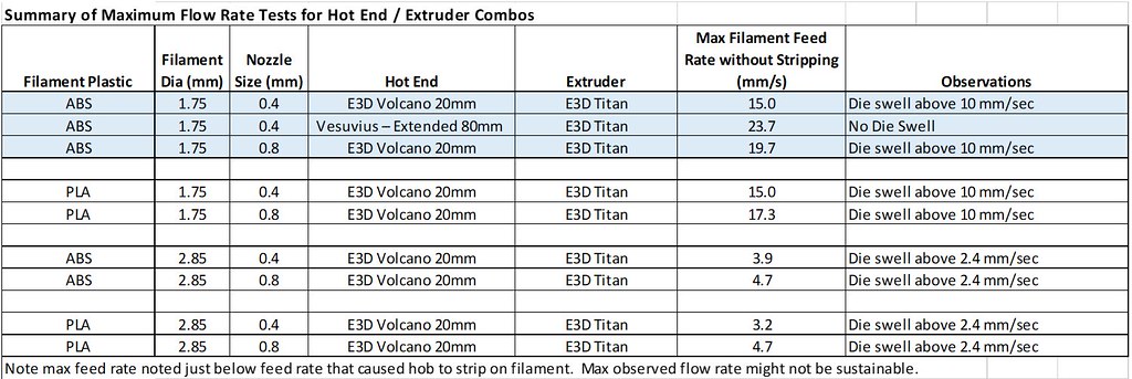
Flow Rate Testing of E3D V6 Volcano Hot End with Titan Extruder
Initial testing is to determine if standard E3D V6 Volcano Hot End and Titan Extruder can achieve adequate flow rate for printing at 1,000 mm/s.
Target flowrate for 1,000 mm/s printing is 576 cm^3/hr. Normal expected flow rate is 288 cm^3/hr based on 0.2 mm layer height with 0.4 mm nozzle. This would require filament feed rate of 33.3 mm/s for 1.75 mm filament and 12.5 mm/s for 2.85 mm filament. Higher flows of 576 cm^3/hr could be required to achieve 0.4 mm layer height with 0.4 mm nozzle OR 0.2 mm layer height with 0.8 mm nozzle. This would require filament feed rate of 66.5 mm/s for 1.75 mm filament and 25.1 mm/s for 2.85 mm filament.
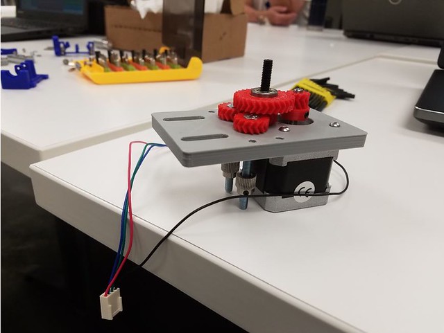
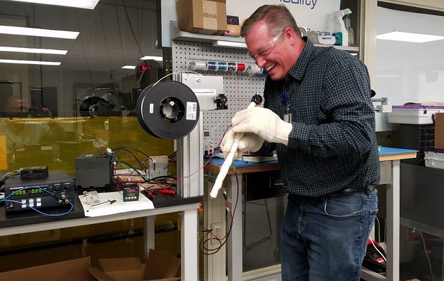
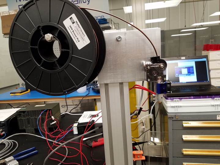
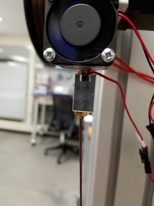
E3D v6 Volcano Hot End is configured with 40W 24V cartridge heater and PT100 RTD. 0.4 and 0.8 mm nozzles will be tested. Both 1.75 mm and 2.85 mm filament will be tested in both ABS and PLA. The system is configured for direct drive with Titan Extruder. Switching between 1.75 and 2.85 mm filament requires interchanging heat break, heat sink, guide tube, PTFE tubing, and nozzles per E3D design. An Automation Direct STP-MTR-17060D NEMA 17 115 oz in stepper motor with STP-DRV-80100 Advanced Drive at 80VDC is assembled with the Titan Extruder. Temperature control by WATLOW 93 controller at 24VDC.


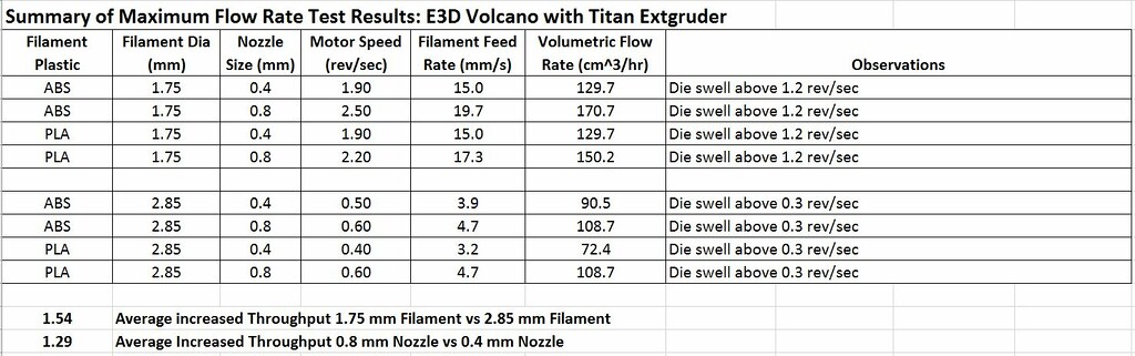
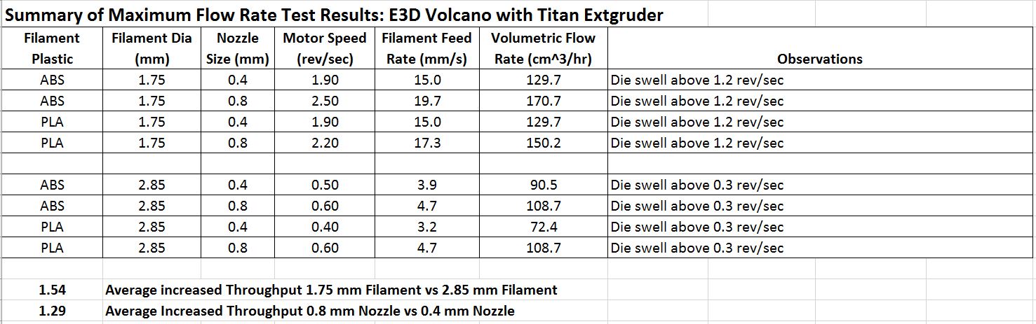
Summary of results from E3D Volcano flow rate testing is in the attached table. Note that the failure mode was always the knurled hobb drive wheel slipping on the filament at which point the filament stopped being driven forward. Speed values in the table were for the maximum sustained speed observed without hobb slippage. This chewed up the filament and the system would not run at a slower speed until the plastic residue was cleaned from the grooves in the hob wheel. We observed at slower speeds the extruded filament was close to the diameter of the nozzle tip. At higher speeds the outer diameter of extruded filament exiting the nozzle was much larger (approx 2X) the diameter of the nozzle tip. We think this is due to die swell and likely due to the filament not being fully melted. We suspect that this might cause issues in printing due to the filament not being extruded at expected diameter and possible issues with interlayer adhesion.
Note that the 1.75 mm filament actually yielded a 54% increase in throughput vs the 2.85 mm filament. We believe this is due to better heat transfer for the 1.75 mm filament, where the 2.85 mm filament can still be cold in the middle.
Edited 2 time(s). Last edit at 03/21/2018 11:36PM by CinciCliff.
Initial testing is to determine if standard E3D V6 Volcano Hot End and Titan Extruder can achieve adequate flow rate for printing at 1,000 mm/s.
Target flowrate for 1,000 mm/s printing is 576 cm^3/hr. Normal expected flow rate is 288 cm^3/hr based on 0.2 mm layer height with 0.4 mm nozzle. This would require filament feed rate of 33.3 mm/s for 1.75 mm filament and 12.5 mm/s for 2.85 mm filament. Higher flows of 576 cm^3/hr could be required to achieve 0.4 mm layer height with 0.4 mm nozzle OR 0.2 mm layer height with 0.8 mm nozzle. This would require filament feed rate of 66.5 mm/s for 1.75 mm filament and 25.1 mm/s for 2.85 mm filament.
E3D v6 Volcano Hot End is configured with 40W 24V cartridge heater and PT100 RTD. 0.4 and 0.8 mm nozzles will be tested. Both 1.75 mm and 2.85 mm filament will be tested in both ABS and PLA. The system is configured for direct drive with Titan Extruder. Switching between 1.75 and 2.85 mm filament requires interchanging heat break, heat sink, guide tube, PTFE tubing, and nozzles per E3D design. An Automation Direct STP-MTR-17060D NEMA 17 115 oz in stepper motor with STP-DRV-80100 Advanced Drive at 80VDC is assembled with the Titan Extruder. Temperature control by WATLOW 93 controller at 24VDC.
Summary of results from E3D Volcano flow rate testing is in the attached table. Note that the failure mode was always the knurled hobb drive wheel slipping on the filament at which point the filament stopped being driven forward. Speed values in the table were for the maximum sustained speed observed without hobb slippage. This chewed up the filament and the system would not run at a slower speed until the plastic residue was cleaned from the grooves in the hob wheel. We observed at slower speeds the extruded filament was close to the diameter of the nozzle tip. At higher speeds the outer diameter of extruded filament exiting the nozzle was much larger (approx 2X) the diameter of the nozzle tip. We think this is due to die swell and likely due to the filament not being fully melted. We suspect that this might cause issues in printing due to the filament not being extruded at expected diameter and possible issues with interlayer adhesion.
Note that the 1.75 mm filament actually yielded a 54% increase in throughput vs the 2.85 mm filament. We believe this is due to better heat transfer for the 1.75 mm filament, where the 2.85 mm filament can still be cold in the middle.
Edited 2 time(s). Last edit at 03/21/2018 11:36PM by CinciCliff.
|
Re: Millennium Peregrine – High Speed Large Format 3D Printer Project - Detailed Build Diary March 21, 2018 10:45PM |
Registered: 6 years ago Posts: 26 |
Vesuvius – Extended 80 mm Hot End Experiment
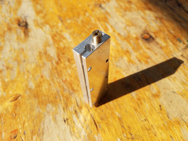
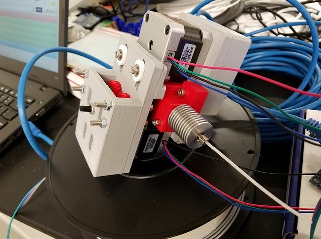
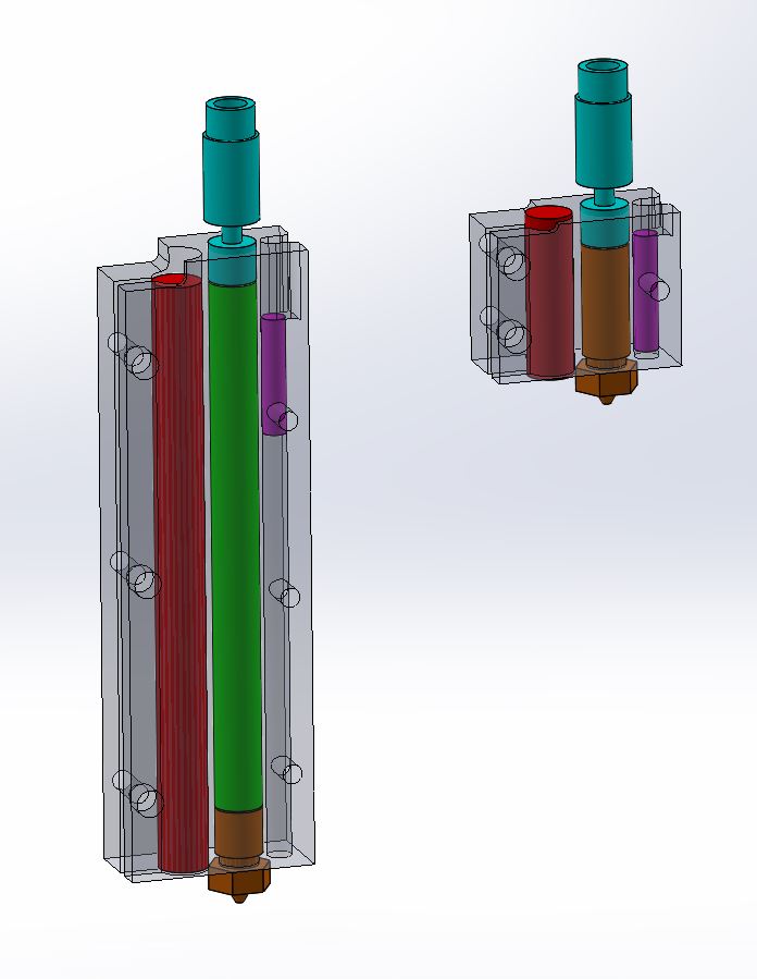
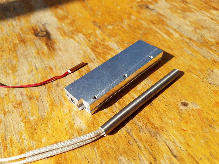
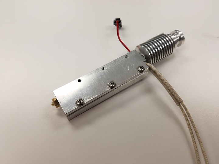
The E3D v6 Volcano hot end has a 20 mm heating length which is a good improvement over the 12 mm in the standard V6. Our hypothesis is that volumetric throughput is limited by heat transfer to the filament and that a longer heating length can provide better heat transfer and high flow rate. To test the flow rate improvements possible with an extended heating zone we constructed the Vesuvius Hot End – an absurd 80 mm long heater block based on the E3D V6 design. We are using the standard E3D V6 nozzle (more options available than the longer Volcano nozzles), the standard E3D V6 heat break, the PT100 RTD temperature sensor, the standard E3D heat sink / fan, and a Titan extruder. The cartridge heater is a 3” long 0.25” diameter 200W 120V heater McMaster Carr 3618K425. We machined an extension tube between the nozzle and heat break from a 68.5 mm long piece of M6 threaded rod with a 2.00 mm reamed hole. Picture below shows a comparison between an E3D Volcano and the 4X as long Vesuvius. There are also a few pictures of the parts (it is so much fun to make a few chips!) Please note we are not suggesting to use such a large hot end for the final build – this for process learning purposes only.


The results from our preliminary testing of the Vesuvius extended length hot end are a little disappointing for flow rate improvements given the 4X melt zone. The good news is that we have observed that the extruded filament has a consistent outside diameter independent of flow rate. The increased diameter die swell we observed with the Volcano is gone.
With 1.75 mm ABS filament and a 0.4 mm nozzle, we observed max flow rate at 3.0 rev/sec motor speed, 23.7 mm/s filament feed rate, 204.8 cm^/hr flow rate. This is a mere 20% improvement vs the Volcano test. We continue to see the same failure mode with the knurled hob wheel slipping on the filament. We tested a theory that the loose fit between our dimensionally 1.68 mm filament and the 2.00 mm bore of the brass adapter tube and nozzle may not be providing good conductive contact with the filament. We made a 68.5 mm long M6 brass adapter tube with a 2.00 mm bore at the heat break side that tapers to 1.60 mm at the nozzle. This did not yield an improvement.
Next we will explore increasing traction force of the extruder to increase driving force / pressure of the molten filament supplied to the nozzle. We have also observed that the 1.75 mm filament is more prone to buckling than the 2.85 mm filament. So while we found the 1.75 m filament to perform best with the Volcano at modest flow rate, we are curious if the 2.85 mm filament will provide better performance now that we have plenty of time to transfer heat to the larger dia core and we expect to be able to provide much more driving force?
Edited 1 time(s). Last edit at 03/21/2018 11:39PM by CinciCliff.
The E3D v6 Volcano hot end has a 20 mm heating length which is a good improvement over the 12 mm in the standard V6. Our hypothesis is that volumetric throughput is limited by heat transfer to the filament and that a longer heating length can provide better heat transfer and high flow rate. To test the flow rate improvements possible with an extended heating zone we constructed the Vesuvius Hot End – an absurd 80 mm long heater block based on the E3D V6 design. We are using the standard E3D V6 nozzle (more options available than the longer Volcano nozzles), the standard E3D V6 heat break, the PT100 RTD temperature sensor, the standard E3D heat sink / fan, and a Titan extruder. The cartridge heater is a 3” long 0.25” diameter 200W 120V heater McMaster Carr 3618K425. We machined an extension tube between the nozzle and heat break from a 68.5 mm long piece of M6 threaded rod with a 2.00 mm reamed hole. Picture below shows a comparison between an E3D Volcano and the 4X as long Vesuvius. There are also a few pictures of the parts (it is so much fun to make a few chips!) Please note we are not suggesting to use such a large hot end for the final build – this for process learning purposes only.
The results from our preliminary testing of the Vesuvius extended length hot end are a little disappointing for flow rate improvements given the 4X melt zone. The good news is that we have observed that the extruded filament has a consistent outside diameter independent of flow rate. The increased diameter die swell we observed with the Volcano is gone.
With 1.75 mm ABS filament and a 0.4 mm nozzle, we observed max flow rate at 3.0 rev/sec motor speed, 23.7 mm/s filament feed rate, 204.8 cm^/hr flow rate. This is a mere 20% improvement vs the Volcano test. We continue to see the same failure mode with the knurled hob wheel slipping on the filament. We tested a theory that the loose fit between our dimensionally 1.68 mm filament and the 2.00 mm bore of the brass adapter tube and nozzle may not be providing good conductive contact with the filament. We made a 68.5 mm long M6 brass adapter tube with a 2.00 mm bore at the heat break side that tapers to 1.60 mm at the nozzle. This did not yield an improvement.
Next we will explore increasing traction force of the extruder to increase driving force / pressure of the molten filament supplied to the nozzle. We have also observed that the 1.75 mm filament is more prone to buckling than the 2.85 mm filament. So while we found the 1.75 m filament to perform best with the Volcano at modest flow rate, we are curious if the 2.85 mm filament will provide better performance now that we have plenty of time to transfer heat to the larger dia core and we expect to be able to provide much more driving force?
Edited 1 time(s). Last edit at 03/21/2018 11:39PM by CinciCliff.
|
Re: Millennium Peregrine – High Speed Large Format 3D Printer Project - Detailed Build Diary March 21, 2018 10:45PM |
Registered: 6 years ago Posts: 26 |
2018 Midwest RepRap Festival
Our team is looking forward to visiting the Midwest RepRap Festival March 23-25, 2018 in Goshen Indiana, USA. We will bring some of our early components to share. We look forward to some great discussions and enjoying some beverages with fellow 3D printing enthusiasts.
Our team is looking forward to visiting the Midwest RepRap Festival March 23-25, 2018 in Goshen Indiana, USA. We will bring some of our early components to share. We look forward to some great discussions and enjoying some beverages with fellow 3D printing enthusiasts.
|
Re: Millennium Peregrine – High Speed Large Format 3D Printer Project - Detailed Build Diary March 22, 2018 11:47AM |
Registered: 11 years ago Posts: 5,780 |
Very interesting stuff!
I think you're going to run into a number of problems that will prevent acceleration to 30k mm/sec^2, among them the plastic parts that the E3D v6 uses to mount the hot-end, and the very small heat break diameter between the hot-end heatsink and heater block. Both are going to flex and maybe break when subjected to such accelerations. The V6 lite hotend uses a single piece SS heatbreak/heatsink that is more robust, but IRIC, runs the teflon liner down to the heater block which isn't going to work with printing high temperature materials. The BullDog extruders are all metal and might be better suited, but they are heavy and come with a 5:1 gear reduction (easily changed by changing the planetary gear box).
Running a printer at 30k mm/sec^2 is going to sound like pounding with a hammer. keeping it from shaking itself apart and/or walking across the floor will be challenges.
The biggest problem of all will be getting a print to look like the intended part. Extrusion is still the biggest problem in FDM 3D printers, and you're pushing way beyond the limits of current software and hardware. Then there's the problem of the molten plastic's momentum. Once it leaves the nozzle you can no longer control it. You might be able to modify the slicer code to account for the momentum of the molten plastic and change the tool path so that the plastic ends up where you want instead of where the nozzle goes, but that will require extreme characterization of the filament. Getting it to work consistently may be a problem due to variations in filament formulation from one manufacturer to another, or even just spool to spool from the same manufacturer.
Another problem with high speed printing is that as each layer is completed faster, the hot nozzle comes around and deposits more hot plastic on top of the still hot previous layer(s), turning the print into a blobby mess. This is already a problem in machines operating at low speeds. Printing faster is only going to make that problem worse. You'll need some way to cool the plastic as it comes out of the nozzle without creating warping and delamination problems.
Edited 2 time(s). Last edit at 03/22/2018 11:57AM by the_digital_dentist.
Ultra MegaMax Dominator 3D printer: [drmrehorst.blogspot.com]
|
Re: Millennium Peregrine – High Speed Large Format 3D Printer Project - Detailed Build Diary March 22, 2018 12:05PM |
Registered: 10 years ago Posts: 14,672 |
@CinciCliff , you may find [somei3deas.wordpress.com] interesting. Since he wrote that, we've implemented nonlinear extrusion in RepRapFirmware, to compensate for the drop off in extrusion rate with increasing back pressure that the Titan and similar extruders exhibit.
Edited 1 time(s). Last edit at 03/22/2018 12:05PM by dc42.
Large delta printer [miscsolutions.wordpress.com], E3D tool changer, Robotdigg SCARA printer, Crane Quad and Ormerod
Disclosure: I design Duet electronics and work on RepRapFirmware, [duet3d.com].
Edited 1 time(s). Last edit at 03/22/2018 12:05PM by dc42.
Large delta printer [miscsolutions.wordpress.com], E3D tool changer, Robotdigg SCARA printer, Crane Quad and Ormerod
Disclosure: I design Duet electronics and work on RepRapFirmware, [duet3d.com].
|
Re: Millennium Peregrine – High Speed Large Format 3D Printer Project - Detailed Build Diary March 22, 2018 11:21PM |
Registered: 6 years ago Posts: 26 |
@the_digital_dentist
Son of MegaMax is an awesome build - I really appreciate your sharing your experience! Is SoM going to be at MRRF this weekend?
I totally agree that we will have some work to do to stiffen up the extruder / hot end and insure it is compatible with the heated enclosure. Our crazy 80 mm long hot end is only intended for some bench flow testing. Not only would the heat break be at risk for failure - but I imagine we would see some serious deflection under 3g's of acceleration which would lead to some inaccurate prints. We haven't dug too deep into alternative extruder / hot end options yet. I will want something very light and stiff that will enable precise positioning of the nozzle. Thanks for suggesting the Bulldog - that design looks beefy and I imagine could be lightened significantly by removing some extra material on the mill. In our early test we have exceeded the traction limit of the single hob / spring on our Titan - so we are planning to play with moving to 2+ hobs to increase traction / pressure into the hot end. Has anyone already make an extruder with more than one drive point?
Thanks for your caution on our target 30,000 mm/^sec^2 acceleration. I appreciate this may sound delusional. In my day job I have designed mechanisms for manufacturing equipment that experience >10X this acceleration 24 hours/day. You are absolutely correct that many machines would shake themselves to death with 3 g's of acceleration. It always helps to keep in mind Newton's Second Law F=ma A higher acceleration target will require higher driving forces and hence higher torque requirements for the motor. I plan to design our machine with a very stiff drivetrain, gantry mechanism, frame, etc to tolerate high forces with minimal deflection. Deflection equates to error in nozzle placement and I assume a sloppy print. (I am amazed by the good quality of prints that come from some very rudimentary and mechanically compliant machines.) Just like in auto racing and rocketry, I think it will be important to minimize the translating mass. Since our goal is to print large (heavy) parts, we are not planning to move the bed in the X-Y plane. So we will move only move the extruder head in the X & Y, as with a Core X-Y Machine. The 3 g target was my initial stab at balancing the need to get up to speed in a reasonable distance while trying to keep this within the performance envelope of stepper motors. I also thought this acceleration is leisurely enough to avoid needing extreme measures to minimize mass. I may adjust this +/- once I know the mass of our extruder(s) and get into detail design for the gantry.
Your comment on pounding did make me think of another question. Is the RepRap firmware set up to generate moves without infinite jerk? For smooth motion with industrial control systems we will control the rate of change in acceleration (jerk) so that it is finite often following a prescribed cam profile. A motion profile with instantly reversing constant acceleration (motor torque) will beat up a machine and will be noisy.
I share your questions and concerns about if the FFF printing process can be controlled at high speed and acceleration. This is the part that might prove be a pipe dream. This quest for the unknown is probably what our team finds most intriguing - so we are really curious to learn where the limits are and see if we can achieve some higher speed and make producing high quality large prints a little less painful. We have found it to be challenging to find information on this subject - so please let me know any work that might better define the limitations or if this is impossible?
We also have a lot of questions about heated build volumes. Have you found that the heated enclosure for SoM has allowed you to produce better quality prints for larger parts? Like you we have been impressed with the flatness of the parts from our Stratasys FORTUS and Dimension printers at work - but we have not been able to hack the printers to print in a cold enclosure so can only compare like parts in our TAZ which do not come out as flat. We have also observed that the layers seems to be better adhered from the Stratasys - but again not sure this is completely due to the heated enclosure. Knowing what you know now, would you use a heated enclosure again? The heated enclose creates some big challenges for selection of mechanical components. We are not planning to move our bed in the Y - so we are hoping to minimize how much we shake the part like a bowl of Jello. We are even considering having the gantry move in the Z - so the part could be completely stationary and undisturbed. Have you noticed issues on your printer with not being able to print the next layer until it can cool? We have not observed the Stratasys pausing to cool a layer. It just maintains the part near the glass transition temperature and keeps on printing. But again we are not sure what will happen if we could speed it up. We only print ABS and ASA in our Stratasys machines and send other materials out. If we added cooling to the nozzle would we lose the advantages gained from the heated build volume? I would love to hear your experiences with the heated build volume - if this is not worth protecting for the machine would be much easier to build!
Thanks again for helping us think through this!
|
Re: Millennium Peregrine – High Speed Large Format 3D Printer Project - Detailed Build Diary March 23, 2018 12:27AM |
Registered: 6 years ago Posts: 26 |
@dc42
Thanks for sharing the Exploration of print speeds with a Diamond hot end! This is a great write up and video that we had not found yet. It was encouraging to see printing at 260 mm/s - especially given this was with Bowden extruders. Has anyone seen similar tests with a direct drive extruder?
Thanks for letting me know about the nonlinear extrusion capability in Marlin. [github.com] This sounds awesome and could be a huge help to us! I am looking forward to reaching a point where we can experiment with this.
|
Re: Millennium Peregrine – High Speed Large Format 3D Printer Project - Detailed Build Diary March 29, 2018 10:40PM |
Registered: 6 years ago Posts: 26 |
The Midwest RepRap Festival MRRF 2018 was an incredible experience! We enjoyed making new friends and learned so much from talking to fellow 3D printing enthusiasts! We were overwhelmed by the number of cool printer builds, brilliant examples of printed parts, and hardware from event sponsors that we are excited to experiment with. Thanks to everyone who talked with us about our high speed printing ideas and for sharing helpful suggestions! We already have a Bondtech extruder from MatterHackers on order to provide better traction for our high throughput printing tests. We also ordered a 3D Solex UM2 Matchless Nozzle and a complete Duet controller set up to experiment with.
Here is a picture of our team with our parts we brought to share at MRRF. We can't wait to see everyone again next year! We are hoping to have a running printer next year and likely many learnings to share!
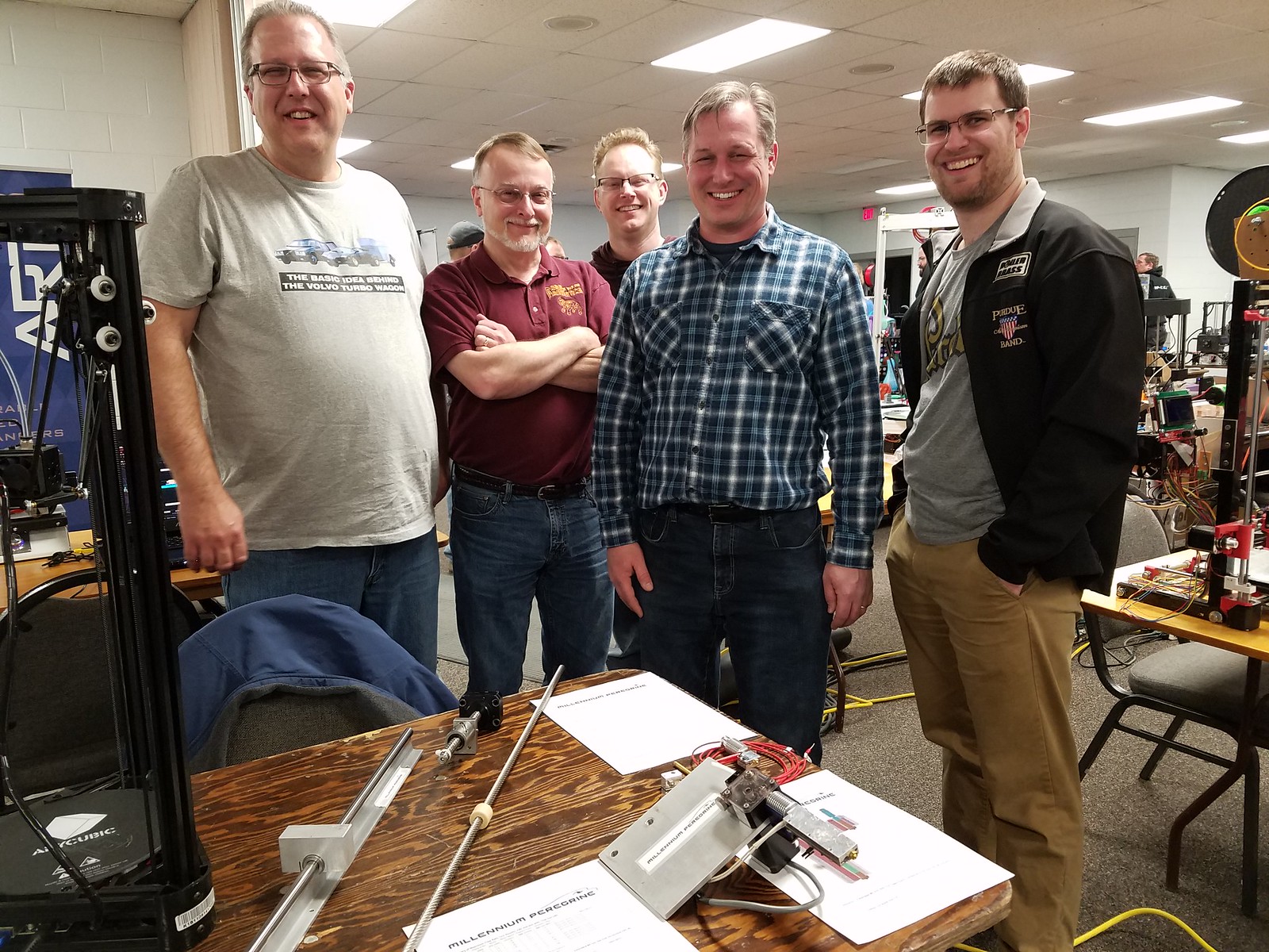
Here is a picture of our team with our parts we brought to share at MRRF. We can't wait to see everyone again next year! We are hoping to have a running printer next year and likely many learnings to share!
|
Re: Millennium Peregrine – High Speed Large Format 3D Printer Project - Detailed Build Diary April 02, 2018 12:28PM |
Registered: 6 years ago Posts: 134 |
Great team
@cinciclif
Nice experiment.
>With 1.75 mm ABS filament and a 0.4 mm nozzle, we observed max flow rate at 3.0 rev/sec motor speed, 23.7 mm/s filament feed rate, 204.8 cm^/hr flow rate. This is a mere 20% improvement vs the Volcano test. We continue to see the same failure mode with the knurled hob wheel slipping on the filament. We tested a theory that the loose fit between our dimensionally 1.68 mm filament and the 2.00 mm bore of the brass adapter tube and nozzle may not be providing good conductive contact with the filament. We made a 68.5 mm long M6 brass adapter tube with a 2.00 mm bore at the heat break side that tapers to 1.60 mm at the nozzle. This did not yield an improvement.
When you increased the length of melting chamber you also increased friction between liquid filament and walls of the heat block. 76 mm length compared to 20 mm Volcano increases resistance up to 3.6 times (it may not be linear due to a different state of the filament at different length).
To increase the contact between the lead screw and filament (to avoid slippage with increased liquid friction) you may need to go for a different extruder design, similar to what MIT guys did: [news.mit.edu]
You may also try using Volcano size and add a more powerful heater or multiple heaters to the block.
|
Re: Millennium Peregrine – High Speed Large Format 3D Printer Project - Detailed Build Diary April 02, 2018 12:54PM |
Registered: 11 years ago Posts: 5,780 |
When and if you guys need print cooling that can move a lot of air, take a look at this: [drmrehorst.blogspot.com]
Ultra MegaMax Dominator 3D printer: [drmrehorst.blogspot.com]
Ultra MegaMax Dominator 3D printer: [drmrehorst.blogspot.com]
|
Re: Millennium Peregrine – High Speed Large Format 3D Printer Project - Detailed Build Diary April 02, 2018 10:18PM |
Registered: 6 years ago Posts: 26 |
@piper3D
Good question - we are not sure if the added length is adding more friction? We plan to do more testing to understand this better. I am borrowing an IR thermal camera to allow us to better evaluate the temperature of the extruded filament. We will also measure the power consumption for the heater.
At MRRF we saw a cool extruder from Bondtech that uses dual drive gears - a hob on both sides of the filament. [www.matterhackers.com] We plan to see if this provides us with the added traction / flow rate we are looking for.
|
Re: Millennium Peregrine – High Speed Large Format 3D Printer Project - Detailed Build Diary April 02, 2018 10:40PM |
Registered: 6 years ago Posts: 26 |
@ the_digital_dentist
That is a fantastic use for a C-Pap blower - awesome! Thanks for taking the time to write your great Tech Topic blogs!
For our heated build enclosure ABS printer, I am thinking about using a localized closed loop air cooling system for the motors, extruder, ball nuts, etc. That would be a great blower to help keep things cool and maybe less complexity than water cooling?
|
Re: Millennium Peregrine – High Speed Large Format 3D Printer Project - Detailed Build Diary April 03, 2018 12:03AM |
Registered: 6 years ago Posts: 134 |
Maybe a related read:
[en.wikipedia.org]
It points that friction loss is
a) proportional to the length of pipe
b) proportional to the viscosity of the liquid and
c) proportional to square root of velocity for nonlaminar flow.
d) for laminar flow, it is proportional to velocity.
So you want to have a shorter length, lower viscosity (may be higher temperature) and most of all eliminate c.
You may achieve laminarity by polishing walls of a nozzle and eliminating edge between heat break and nozzle. Later may be achieved for example by combining nozzle with heat break in a single unit.
In the Volcano head, the nozzle is long so the connection between heat break and the nozzle is high at the length where plastic is not completely melted so the edge will not introduce major turbulence.
|
Re: Millennium Peregrine – High Speed Large Format 3D Printer Project - Detailed Build Diary April 04, 2018 09:48PM |
Registered: 6 years ago Posts: 26 |
@piper3d
Great question - we have not measured what is contributing to the back pressure and friction of forcing the filament into the extruder at high speeds. I was assuming that most of the pressure drop would be due to the flow restriction through the nozzle. A 0.4 mm nozzle has 1/25 the cross-sectional area vs the 2.0 mm filament supply hole. The average velocity through the nozzle would be 25X the average velocity through the pipe, so I was assuming the losses due to the pipe to be relatively low. I do recall feeling a surprising amount of resistance when pushing the filament at slow speed by hand. Molten ABS is a non-Newtonian shear thinning fluid - so it may behave differently than we would intuitively expect - and it may actually flow easier through a high shear nozzle?. I will try an experiment to flow through the 2 mm pipe with the 0.4 mm flow restriction removed and the transition between pipe adapter and nozzle eliminated.
It would be really helpful to measure the pressure inside of the pipe or the force to press the filament. Has anyone had success measuring the torque on a stepper motor through motor current to resolve force applied to the filament?
Airtripper has done some cool work to add a load cell to measure force inside a Bowden extruder. [airtripper.com] Has anyone made a load cell adapter to mount in the "groovemount" between a standard E3D extruder and heat sink?
|
Re: Millennium Peregrine – High Speed Large Format 3D Printer Project - Detailed Build Diary April 05, 2018 09:24AM |
Registered: 11 years ago Posts: 5,780 |
Quote
CinciCliff
@ the_digital_dentist
For our heated build enclosure ABS printer, I am thinking about using a localized closed loop air cooling system for the motors, extruder, ball nuts, etc. That would be a great blower to help keep things cool and maybe less complexity than water cooling?
And less likely to leak liquid coolant all over your printer, too. We have a couple old stratasys printers at the makerspace that have flexible hoses that bring room temp air in to cool the hot-end and exhaust back out to the room. The enclosure is operated at 70C to prevent problems with ABS printing.
Ultra MegaMax Dominator 3D printer: [drmrehorst.blogspot.com]
|
Re: Millennium Peregrine – High Speed Large Format 3D Printer Project - Detailed Build Diary April 06, 2018 09:05PM |
Registered: 6 years ago Posts: 26 |
Great point on leakage - we wouldn't our nice printed parts to float away in a coolant leak tsunami! 
Thanks for the tip on the air cooling hoses used on the older Statasys printers! Good to know this is proven technology - our newer printers at work do not have these cooling hoses. For anyone curious I found these great pictures from a teardown of an FDM 2000:
[frankieflood.blogspot.com]
Thanks for the tip on the air cooling hoses used on the older Statasys printers! Good to know this is proven technology - our newer printers at work do not have these cooling hoses. For anyone curious I found these great pictures from a teardown of an FDM 2000:
[frankieflood.blogspot.com]
|
Re: Millennium Peregrine – High Speed Large Format 3D Printer Project - Detailed Build Diary February 21, 2019 08:13AM |
Registered: 5 years ago Posts: 207 |
|
Re: Millennium Peregrine – High Speed Large Format 3D Printer Project - Detailed Build Diary February 27, 2019 08:35PM |
Registered: 6 years ago Posts: 26 |
@NitroFreak
Thanks for your interest. Our Team has continued to focus on understanding the challenge of high flow rate extrusion. Our latest force vs flow rate test results are encouraging. We need to summarize our test data and will post an update soon.
Edited 1 time(s). Last edit at 02/27/2019 08:36PM by CinciCliff.
|
Re: Millennium Peregrine – High Speed Large Format 3D Printer Project - Detailed Build Diary February 28, 2019 03:26PM |
Registered: 11 years ago Posts: 5,780 |
New high volume hot-end: [e3d-online.com]
Ultra MegaMax Dominator 3D printer: [drmrehorst.blogspot.com]
Ultra MegaMax Dominator 3D printer: [drmrehorst.blogspot.com]
|
Re: Millennium Peregrine – High Speed Large Format 3D Printer Project - Detailed Build Diary February 28, 2019 11:50PM |
Registered: 6 years ago Posts: 26 |
@ the_digital_dentist
Cool - Thanks for sharing that the E3D SuperVolcano is out! Sanjay showed us this at MRRF and it looks like a great idea! We will order one to test.
This looks like a really nice design! I appreciate the one piece nozzle. Our prototype uses standard V6 nozzle mated up to an M6 threaded rod sleeve. We added a screwdriver slot at the end of our sleeve - but this has been challenging to remove from the block once we gum it up with filament.
With a 50 mm block length, this looks more practical to mount to a printer than the 80 mm block we built.
The SuperVolcano might get us closer to the target Millennium Peregrine flow rate. SuperVolcano is rated for 6600 mm^/min (46 mm/sec for 1.75 mm filament). Our target is 9600 mm^/min (66.5 mm/sec for 1.75 mm filament).
|
Re: Millennium Peregrine – High Speed Large Format 3D Printer Project - Detailed Build Diary March 01, 2019 02:36AM |
Registered: 6 years ago Posts: 1,007 |
Quote
CinciCliff
@ the_digital_dentist
Cool - Thanks for sharing that the E3D SuperVolcano is out! Sanjay showed us this at MRRF and it looks like a great idea! We will order one to test.
This looks like a really nice design! I appreciate the one piece nozzle. Our prototype uses standard V6 nozzle mated up to an M6 threaded rod sleeve. We added a screwdriver slot at the end of our sleeve - but this has been challenging to remove from the block once we gum it up with filament.
With a 50 mm block length, this looks more practical to mount to a printer than the 80 mm block we built.
The SuperVolcano might get us closer to the target Millennium Peregrine flow rate. SuperVolcano is rated for 6600 mm^/min (46 mm/sec for 1.75 mm filament). Our target is 9600 mm^/min (66.5 mm/sec for 1.75 mm filament).
And why a threaded sleeve ? I make my own long hot end (Volcano style currently), only thread what is required for the standard nozzle and use a 5mm OD 2mm ID Al sleeve. It also serves as a gasket BTW. Easy to remove when hot, just push it out.
I see these extra long nozzles as an hindrance.
And why in hell did the first to make these nozzles choose M6 and not M6 fine ????? OK, at least it isn't UNC
"A comical prototype doesn't mean a dumb idea is possible" (Thunderf00t)
|
Re: Millennium Peregrine – High Speed Large Format 3D Printer Project - Detailed Build Diary March 01, 2019 10:21AM |
Registered: 11 years ago Posts: 5,780 |
I use antiseize compound on everything that screws into the heater block. No problem getting it apart again. It does smoke for a few minutes when you first heat it up...
I suspect they use coarse threads because the nozzle is going into aluminum and fine threads are easy to strip.
Ultra MegaMax Dominator 3D printer: [drmrehorst.blogspot.com]
I suspect they use coarse threads because the nozzle is going into aluminum and fine threads are easy to strip.
Ultra MegaMax Dominator 3D printer: [drmrehorst.blogspot.com]
|
Re: Millennium Peregrine – High Speed Large Format 3D Printer Project - Detailed Build Diary March 11, 2019 09:49PM |
Registered: 6 years ago Posts: 26 |
Our Team has continued to focus on understanding the challenge of high flow rate extrusion.
We continued testing to understand flow rate capacity of the Vesuvius extended length and Volcano hot ends driven by E3D Titan and Bondtech QR extruders.
-
Summary of test results is listed below. Our highest 1.75 mm ABS filament feed rate of 26.0 mm/s through a 0.4 mm nozzle was achieved with the extended length Vesuvius Hot End and Bondtech QR extruder. This is around 39% of our target filament feed rate of 66.5 mm/s.
Please note that we chose to not publish the Bondtech extruder data to a public forum because we are concerned that there may be an error with our test method. In our flow rate testing we did not observe a significant increase in flow rate with the Bondtech QR vs the E3D Titan. Later testing demonstrated the Bondtech QR to produce 33-37% more thrust than the E3D Titan extruder before slipping – so we would expect to see a significant increase in flow rate. We are unsure why our flow rate testing did not yield similar improvements. There are many potential sources of error since these tests were conducted days apart using different motors, drives, filament, temperature controllers, etc.
We observed that the extruded plastic looks more consistent and had less die swell from the longer heat zone of Vesuvius vs the Volcano. With the Volcano, we observed some unusual vibration of the extrusion above 10 mm/sec that resulted in a twisted structure when cooled.
In addition to a 2.00 mm straight reamed cylindrical bore inside Vesuvius, we also tested a couple of tapered bores in an attempt to improve melting and increase flow rate. We tested 2 tapered bores - 2.00 to 1.60 mm and 2.00 to 1.65 mm. The smaller taper that necked down to 1.60 mm clogged with filament. We did not observe a significant improvement with the larger 2.00 to 1.65 mm taper.
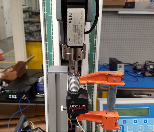
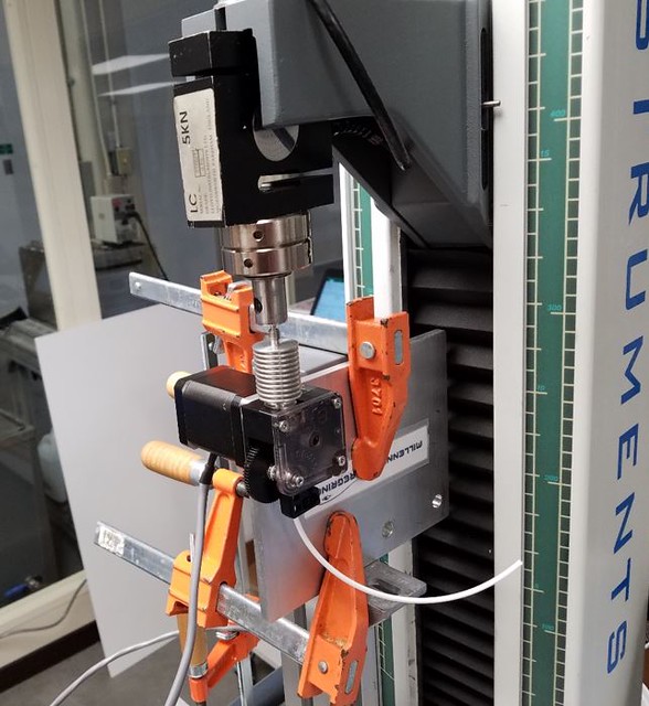
To better understand the traction capability of our extruders we drove the E3D Titan and Bondtech QR to pull filament against a load cell on a tensile tester. Both extruders are able to generate enough traction in tension to break the filament (around 21 lbf).
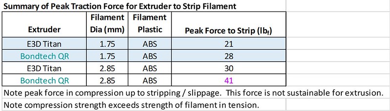
Next we tested pushing the filament in compression. The filament pressed a steel pin in the heat sink against a load cell. The filament was pushed in compression until the hob teeth slipped and stripped the filament. Summary data is below. In this test the Bondtech QR with dual driven hobs produced greater traction force than the E3D Titan with a single hob. These tests were conducted back to back under the same conditions.
-
-
We continued testing to understand flow rate capacity of the Vesuvius extended length and Volcano hot ends driven by E3D Titan and Bondtech QR extruders.
-
Summary of test results is listed below. Our highest 1.75 mm ABS filament feed rate of 26.0 mm/s through a 0.4 mm nozzle was achieved with the extended length Vesuvius Hot End and Bondtech QR extruder. This is around 39% of our target filament feed rate of 66.5 mm/s.
Please note that we chose to not publish the Bondtech extruder data to a public forum because we are concerned that there may be an error with our test method. In our flow rate testing we did not observe a significant increase in flow rate with the Bondtech QR vs the E3D Titan. Later testing demonstrated the Bondtech QR to produce 33-37% more thrust than the E3D Titan extruder before slipping – so we would expect to see a significant increase in flow rate. We are unsure why our flow rate testing did not yield similar improvements. There are many potential sources of error since these tests were conducted days apart using different motors, drives, filament, temperature controllers, etc.
We observed that the extruded plastic looks more consistent and had less die swell from the longer heat zone of Vesuvius vs the Volcano. With the Volcano, we observed some unusual vibration of the extrusion above 10 mm/sec that resulted in a twisted structure when cooled.
In addition to a 2.00 mm straight reamed cylindrical bore inside Vesuvius, we also tested a couple of tapered bores in an attempt to improve melting and increase flow rate. We tested 2 tapered bores - 2.00 to 1.60 mm and 2.00 to 1.65 mm. The smaller taper that necked down to 1.60 mm clogged with filament. We did not observe a significant improvement with the larger 2.00 to 1.65 mm taper.
To better understand the traction capability of our extruders we drove the E3D Titan and Bondtech QR to pull filament against a load cell on a tensile tester. Both extruders are able to generate enough traction in tension to break the filament (around 21 lbf).
Next we tested pushing the filament in compression. The filament pressed a steel pin in the heat sink against a load cell. The filament was pushed in compression until the hob teeth slipped and stripped the filament. Summary data is below. In this test the Bondtech QR with dual driven hobs produced greater traction force than the E3D Titan with a single hob. These tests were conducted back to back under the same conditions.
-
-
|
Re: Millennium Peregrine – High Speed Large Format 3D Printer Project - Detailed Build Diary March 11, 2019 09:59PM |
Registered: 6 years ago Posts: 26 |
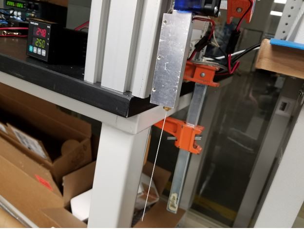
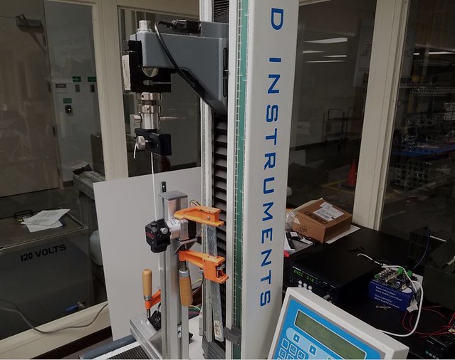
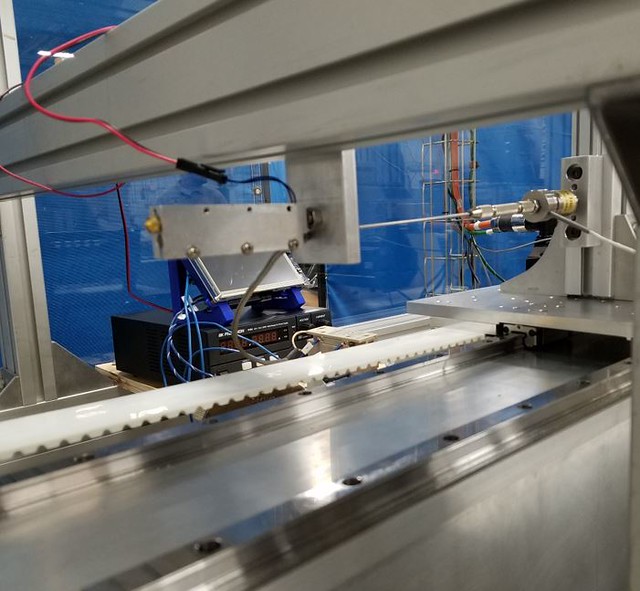
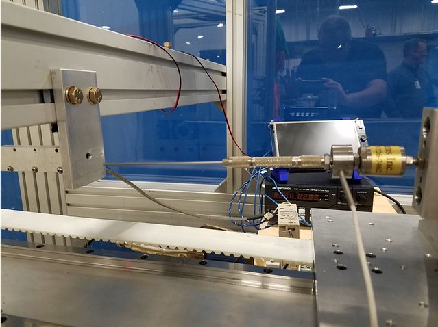
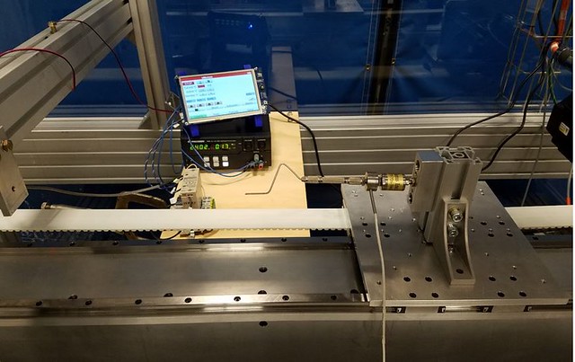
We used a high speed / high force linear motion test stand to measure the extrusion force required to extrude fully molten plastic at various filament feed rates. The Vesuvius extended hot end was fitted with a precision 2.02 mm bore and a matched 2.00 mm piston pin. The piston pin was attached by a load cell to the linear motion sled. An 80 mm length of 1.75 mm filament was manually loaded into the hot end and given time to melt. The piston rod was aligned to, an inserted in, the hot end bore, and the sled was advanced 64 mm under controlled, aggressive acceleration, constant velocity, and aggressive deceleration. Load cell force vs displacement was recorded with a data acquisition system.
-
-

-
Ouch – Buckled piston rod after 1500 mm/s test.
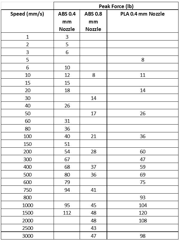
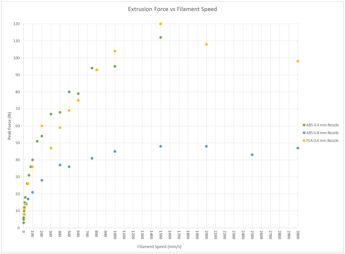
Data is summarized in table and graphs below. We demonstrated 1500 mm/sec of ABS 1.75 mm filament feed rate through a 0.4 mm nozzle with 112 lbf extrusion force (23,000 psi). This was limited by the buckling strength of the piston rod.
-
-
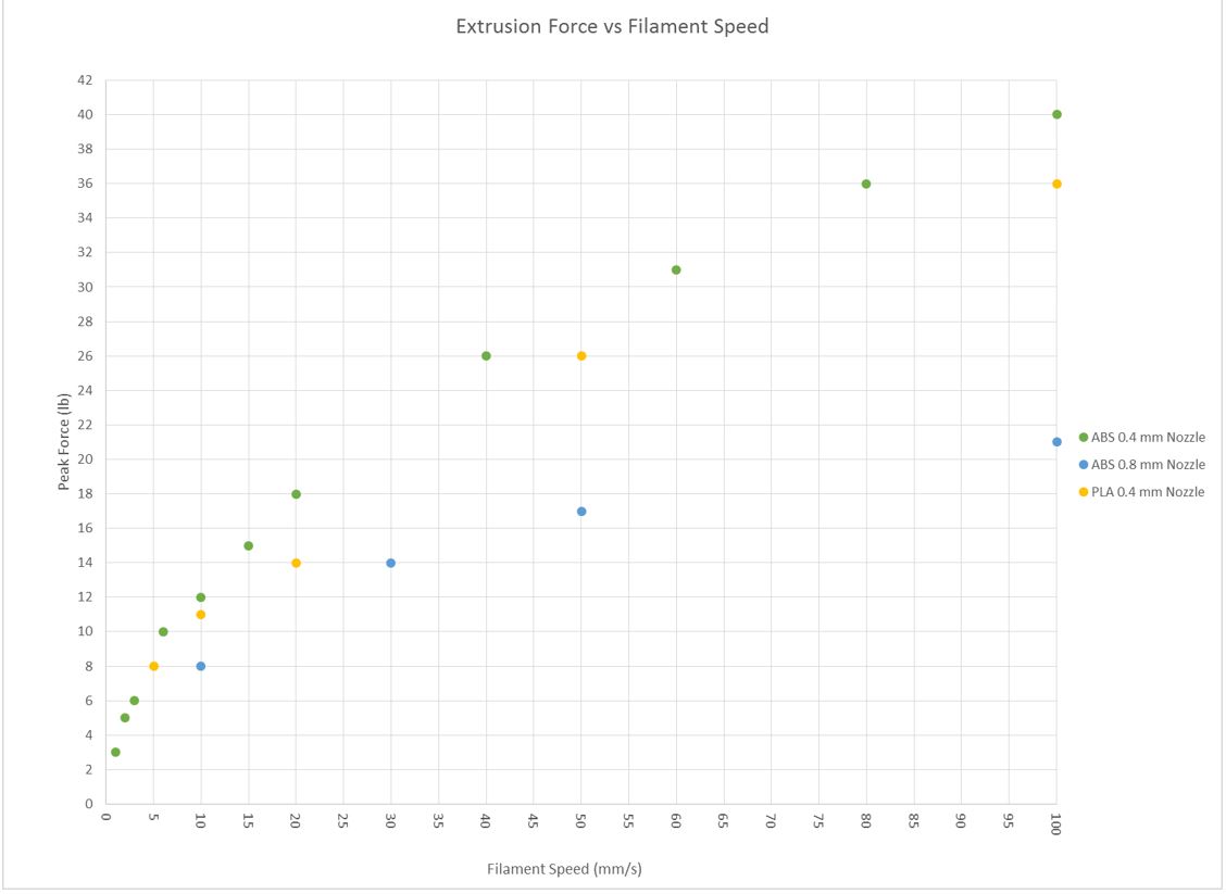
Based on this data, our target speed of 67 mm/s should be possible with at least 33 lbf of extrusion force (6,800 psi), if the hot end can fully melt the moving filament. This confirms that higher traction force must be supplied than possible with the standard E3D Titan (21 lbf) and Bondtech QR (28 lbf). With 1.75 mm Titan Pushing Force of 21 lb., linear flow rate testing predicts max filament speed above 20 mm/s for 1.75 mm ABS through a 0.4 mm nozzle. 23.7 mm/s flow from Vesuvius and Titan is consistent.
Mike with the “Atomic Thruster” 4WD (4 Driven Hobs / 2 Drive Motors) Prototype. This is currently under development but we believe has potential to achieve 33+ lbf of traction force.
-
-
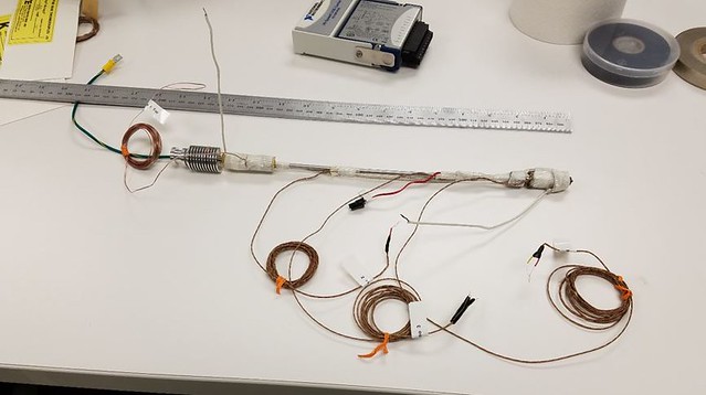
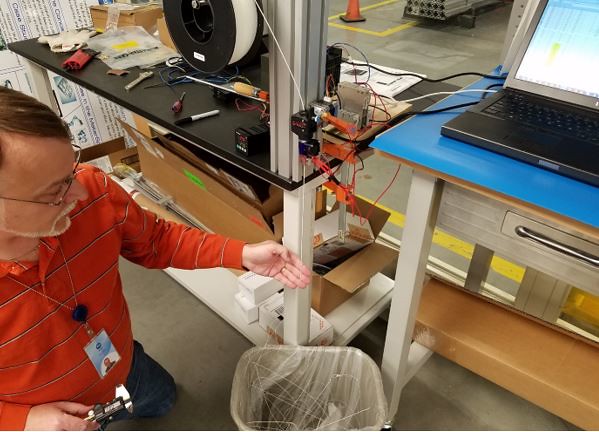
We wanted to test a hot end with a heat capacity higher than our 80 mm Vesuvius – so we created this 300 mm version. What should we call it?

-
Our hot end smoked badly due to inconsistent temperature control across the length of the heater cable!
Don’t worry, Matt didn’t inhale…

-
-
-
Ouch – Buckled piston rod after 1500 mm/s test.
Data is summarized in table and graphs below. We demonstrated 1500 mm/sec of ABS 1.75 mm filament feed rate through a 0.4 mm nozzle with 112 lbf extrusion force (23,000 psi). This was limited by the buckling strength of the piston rod.
-
-
Based on this data, our target speed of 67 mm/s should be possible with at least 33 lbf of extrusion force (6,800 psi), if the hot end can fully melt the moving filament. This confirms that higher traction force must be supplied than possible with the standard E3D Titan (21 lbf) and Bondtech QR (28 lbf). With 1.75 mm Titan Pushing Force of 21 lb., linear flow rate testing predicts max filament speed above 20 mm/s for 1.75 mm ABS through a 0.4 mm nozzle. 23.7 mm/s flow from Vesuvius and Titan is consistent.
Mike with the “Atomic Thruster” 4WD (4 Driven Hobs / 2 Drive Motors) Prototype. This is currently under development but we believe has potential to achieve 33+ lbf of traction force.
-
-
We wanted to test a hot end with a heat capacity higher than our 80 mm Vesuvius – so we created this 300 mm version. What should we call it?
-
Our hot end smoked badly due to inconsistent temperature control across the length of the heater cable!
Don’t worry, Matt didn’t inhale…
|
Re: Millennium Peregrine – High Speed Large Format 3D Printer Project - Detailed Build Diary March 11, 2019 10:13PM |
Registered: 11 years ago Posts: 5,780 |
This is all very interesting- it's good to see someone doing some real life testing instead of just posting pretty CAD renderings.
Assuming you achieve the high flow rate you're after, how are you going to cool the print so that the next layer isn't deposited on still-soft plastic? And how do you do that without the print warping, splitting, or letting go of the bed (will it be printed on a bed?)? I suspect there will be some minimum print size limit for printing at that high flow rate or you'll end up with a pile of plastic spaghetti.
Ultra MegaMax Dominator 3D printer: [drmrehorst.blogspot.com]
|
Re: Millennium Peregrine – High Speed Large Format 3D Printer Project - Detailed Build Diary March 11, 2019 11:35PM |
Registered: 6 years ago Posts: 26 |
@the_digital_dentist
Thanks - we have been having fun running some experiments with high flow extrusion.
You ask a great question about how to avoid creating a bowl of spaghetti or warm gummy worms. Our base plan is to use a second extruder with soluble support material to help stabilize voids between the warm extruded plastic. We also would like to explore building inside a heated temperature controlled enclosure to minimize warpage. These strategies seem to work for high end commercial machines - but we have not seen this demonstrated at extreme speeds. I imagine there will be a lot more to learn and we will likely need to adjust our plans. Does these seem like it could work - please let us know if others have already uncovered pitfalls we can avoid?
If we print PLA without a second support material, perhaps our large build envelope will work in our favor and will give each layer a reasonable amount of time to cool off. We scrounged a larger thermo-electric chiller / heater from the salvage yard - so we might play with a cooled build enclosure instead of heated in this case?
Yes we are imagining a conventional horizontal planar build plate. The hot end is horizontal on the linear motion test stand only because we were borrowing an existing test stand for our extrusion force vs speed test. We are planning to use a vertical extruder nozzle moving by an x-y-z gantry. We want to avoid accelerating the build due to the mass of a large part and to avoid distorting a warm soft part. Z motion continues to be a topic of debate as it is complex to move the gantry in the Z relative to the part.
|
Re: Millennium Peregrine – High Speed Large Format 3D Printer Project - Detailed Build Diary March 11, 2019 11:45PM |
Registered: 6 years ago Posts: 26 |
Here are a couple of videos to accompany our latest post.
This video is Vesuvius (custom 80 mm long hot end) with Bondtech extruder running 1.75 mm ABS filament through a 0.4 mm nozzle at 26 mm/sec filament feed rate. We could not run faster without the extruder stripping / slipping on the filament.
[youtu.be]
This video is the Linear Motion Test stand to measure Linear Extrusion Force vs Filament Velocity for molten 1.75 mm filament in Vesuvius with a 0.4 mm nozzle. The video shows a few different speed from slow to 1500 mm/sec filament feed rate.
[youtu.be]

Sorry, only registered users may post in this forum.