Millennium Peregrine – High Speed Large Format 3D Printer Project - Detailed Build Diary
Posted by CinciCliff
|
Re: Millennium Peregrine – High Speed Large Format 3D Printer Project - Detailed Build Diary March 12, 2019 07:12AM |
Registered: 11 years ago Posts: 5,780 |
What is your intended use for this machine?
PLA, while relatively easy to print because of low shrinkage and bed temperature, is generally a crappy material, best suited to throw-away stuff like Yoda heads and tugboats. If you leave it in a hot car or exposed to other source of heat, it will soften and deform. PLA absorbs moisture from the air (PETG is even worse in that regard) which will ruin print surface quality as the absorbed water boils and bubbles in the hot-end. When PLA filament absorbs moisture, it becomes brittle and impossible to feed. The prints absorb moisture from the air and become brittle, too.
Maybe you could intentionally inject water into the hot end while it's printing to turn the plastic into foam...
Speaking of foam, I did some tests a few years ago when I was looking for a substitute for the sacrificial foam bed for a 90s era Stratasys printer. Those printers used open cell urethane foam as a bed to print ABS. No bed heater was required (but they did print inside a 70C oven). Stratasys charged an arm and a leg for the foam so I went looking for a substitute and found that PIR (polyisocyanurate) foam worked well. You can buy it in 4'x8' sheets at Home Depot for $15. When you use the foam, you don't really have to level the bed- you bury the nozzle in the foam and print on a raft. The nozzle will create its own level first layer.
Printing on PIR foam
Does it stick? Sure!
I also did some experiments with extruding- to maximize push force. I built an extruder that used counter-rotating nuts to push the filament into the hot end. I had some problems with retraction, and it was not a high speed extruder the way I built it, but the same principle could be used with longer pitch screws to speed things up. See: [vimeo.com] and [vimeo.com] I've seen a commercial unit using the same principle that fixed the retraction problem by adding some anti-twist rollers that roll along the length of the filament and prevent it from twisting in the extruder (the problem I had) when it retracts.
Edited 1 time(s). Last edit at 03/12/2019 07:14AM by the_digital_dentist.
Ultra MegaMax Dominator 3D printer: [drmrehorst.blogspot.com]
|
Re: Millennium Peregrine – High Speed Large Format 3D Printer Project - Detailed Build Diary March 12, 2019 11:32PM |
Registered: 6 years ago Posts: 26 |
@the_digital_dentist
Thanks for another thought provoking post!
Our long term vision for this printer is to print large parts primarily from ABS and other engineering thermoplastics such as Nylon 12, Polycarbonate, ASA, and maybe even high temp materials like Ultem and PEEK. Most of our team members have managed to print useful non-Yoda head items on our small printers at home from PLA - so we may print PLA on the larger printer too if PLA meets the requirements for the printed object.
Thanks for sharing the PIR foam sacrificial bed - that is something we will have to keep in mind - especially since it held up in the heated enclosure of an older Stratasys. We might use vacuum to hold a thin flexible sheet as a build surface - maybe Kapton or PEI? Our Fortus printer uses a thin plastic sheet and it is really handy to lift a large part with support material out and peel the sheet away.
Your SnakeBite Extruder with counter rotating RH and LH 6-32 nuts (for 3 mm filament) is VERY COOL! This sounds similar to what MIT is using for their very high speed printer although they apparently have pre-threaded the filament. It looks like the minor / major diameter of the UNC 6-32 threads are a nice fit for the 3 mm filament. I assume you used the nuts to form threads in the filament? Once the first nut formed a RH thread in the filament, how did the LD nut interact with the filament - did it just form LH threads across the RH threads? Did you ever measure the compressive force you could generate? Did you run this enough to get a feel for wear on the nuts?
Our high flow rate extrusion testing has indicated a very strong speed advantage for 1.75 mm filament vs 3 mm (takes much more time to melt the 3 mm filament). This smaller 1.75 m filament looks like it would be a good "lucky" fit with a UNC 2-56 threaded nut. These nuts are really tiny - so it seems like it would be a challenge to execute? So far we have been experimenting with 2 driven pairs of hobs in a row for a 4WD system but we have been had issues with the filament buckling in between the pairs of drive hobs. Getting a high force extruder working is our next piece of work.
Are you planning to join MRRF the end of the month? We will be there - it would be fun to grab a beer with you and anyone else interested in talking about big fast printers.
|
Re: Millennium Peregrine – High Speed Large Format 3D Printer Project - Detailed Build Diary March 14, 2019 07:46AM |
Registered: 11 years ago Posts: 5,780 |
A lot of people print 3D printer parts using PLA. It's great as long as you can control the environment the printer is in. I have seen more than one post on reddit (ugh!) in which someone was lamenting that they were taking their printer to a friend's house, or moving, and left the printer in their car for an hour and it melted. A lot of people print cell phone holders for their cars only to discover that you can't do that with PLA.
In the snakebite extruder, the nuts just rolled threads into the filament. The right and left hand threads cut across each other. I found that a bit of dust was produced, and the problem I ultimately had was that retraction didn't work well because one nut or the other would hold the filament tighter and the filament would rotate when you tried to retract. That created some interesting looped blebs in the print surface (at least, I think that's what created the blebs):
Anyway, I found that this particular method wasn't tolerant of the relatively wide variation in filament diameters at the time (6 years ago) and I didn't pursue it any further. What it needed was a means to follow the filament diameter- maybe a spring loaded threaded collet instead of a nut, and a pizza cutter wheel running along the length of the filament to prevent the filament from twisting (which was what I was doing with the counter rotating nuts and didn't work so well). If you have a pizza cutter wheel you only need one nut to drive the filament (like the MIT device). The thread pitch was very small so the speed was limited but push force was very high. I did a crude test of the push force on the filament and it was on the order of 12 kg IRIC. My whole reason for making the device was to get high push force to keep filament flowing in the event of a partial blockage or a slightly too low temperature in the hot-end. At that time I was struggling with the crappy extruder and hot-end designs (I had a budaschnozzle on the snakebite- what a stupidly awful hot-end) and my more limited understanding of how they work and trying to improve reliability.
Maybe you need to get one of the manufacturers to make you some 1 mm filament. That should melt fast.
Ultra MegaMax Dominator 3D printer: [drmrehorst.blogspot.com]
In the snakebite extruder, the nuts just rolled threads into the filament. The right and left hand threads cut across each other. I found that a bit of dust was produced, and the problem I ultimately had was that retraction didn't work well because one nut or the other would hold the filament tighter and the filament would rotate when you tried to retract. That created some interesting looped blebs in the print surface (at least, I think that's what created the blebs):

Anyway, I found that this particular method wasn't tolerant of the relatively wide variation in filament diameters at the time (6 years ago) and I didn't pursue it any further. What it needed was a means to follow the filament diameter- maybe a spring loaded threaded collet instead of a nut, and a pizza cutter wheel running along the length of the filament to prevent the filament from twisting (which was what I was doing with the counter rotating nuts and didn't work so well). If you have a pizza cutter wheel you only need one nut to drive the filament (like the MIT device). The thread pitch was very small so the speed was limited but push force was very high. I did a crude test of the push force on the filament and it was on the order of 12 kg IRIC. My whole reason for making the device was to get high push force to keep filament flowing in the event of a partial blockage or a slightly too low temperature in the hot-end. At that time I was struggling with the crappy extruder and hot-end designs (I had a budaschnozzle on the snakebite- what a stupidly awful hot-end) and my more limited understanding of how they work and trying to improve reliability.
Maybe you need to get one of the manufacturers to make you some 1 mm filament. That should melt fast.
Ultra MegaMax Dominator 3D printer: [drmrehorst.blogspot.com]
|
Re: Millennium Peregrine – High Speed Large Format 3D Printer Project - Detailed Build Diary April 05, 2019 07:39PM |
Registered: 5 years ago Posts: 207 |
I think you may want to look into nonlinear heating tubes for melting the filament.
As in, not just a 300mm long 2mm tube, but a tube that expands in diameter to accommodate a larger volume of molten plastic, and then constricts again to lead to the nozzle. This allows for spontaneous bursts of extrusion force without running out of molten filament.
The Advantage would also be that one would not have the extreme shear force of pushing a cylinder of molten plastic at high speed through a long and narrow tube. It creates a lot of friction between the wall and the filament which has to be overcome.
I suspect the MXT Metering Extruder Technology from Bigrep (they claim 500 cm³/h throughput with a 1mm nozzle)
[vimeo.com]
and also the Mastiff extruder from Titan robotics works after this principle ( I think)
Also, Titan Robotics released this high speed 3d printer.
[www.youtube.com]
They claim 5G´s acceleration, so your 3G´s should definitely be possible.
For my next printer I also want to experiment with a fast accelerating XY stage, but only as a 200x 200y mm printer maybe to keep the weight on the low side. I thought of maybe doing it as a belt printer so the vibrations will not affect the bed as much.
I would also be happy with about 3G´s, should be possible with some servos. I already used one 180w servo for my Y stage in my current printer, and that can manage 1.3G´s on my 3.5 kg Y stage. But i could gear it down even more to up that number ( of course sacrificing top speed, but it would result in faster print times for smaller parts)
Cheers
Max
Edited 3 time(s). Last edit at 04/05/2019 07:53PM by NitroFreak.
As in, not just a 300mm long 2mm tube, but a tube that expands in diameter to accommodate a larger volume of molten plastic, and then constricts again to lead to the nozzle. This allows for spontaneous bursts of extrusion force without running out of molten filament.
The Advantage would also be that one would not have the extreme shear force of pushing a cylinder of molten plastic at high speed through a long and narrow tube. It creates a lot of friction between the wall and the filament which has to be overcome.
I suspect the MXT Metering Extruder Technology from Bigrep (they claim 500 cm³/h throughput with a 1mm nozzle)
[vimeo.com]

and also the Mastiff extruder from Titan robotics works after this principle ( I think)

Also, Titan Robotics released this high speed 3d printer.
[www.youtube.com]
They claim 5G´s acceleration, so your 3G´s should definitely be possible.
For my next printer I also want to experiment with a fast accelerating XY stage, but only as a 200x 200y mm printer maybe to keep the weight on the low side. I thought of maybe doing it as a belt printer so the vibrations will not affect the bed as much.
I would also be happy with about 3G´s, should be possible with some servos. I already used one 180w servo for my Y stage in my current printer, and that can manage 1.3G´s on my 3.5 kg Y stage. But i could gear it down even more to up that number ( of course sacrificing top speed, but it would result in faster print times for smaller parts)
Cheers
Max
Edited 3 time(s). Last edit at 04/05/2019 07:53PM by NitroFreak.
|
Re: Millennium Peregrine – High Speed Large Format 3D Printer Project - Detailed Build Diary April 07, 2019 11:03PM |
Registered: 6 years ago Posts: 26 |
@NitroFreak
Thanks I really appreciate you sharing these links and your suggestion!
Wow - the MXT technology from BigRep looks like a breakthrough to not just for extrusion speed but also precise control of the filament. It appears what they are doing is to feed the filament into a melting reservoir, then a separate servo driven metering pump (presumably a gear pump) . I found this explanation: [www.fabbaloo.com] BigRep claims to have already printed at 600 mm/s on their Pro model with a 0.6 mm nozzle and their upcoming Edge Printer should print at 1000 mm/s! [bigrep.com]
The secondary metering pump seems like a really great idea for better control of the extruded filament. At very high speeds and accelerations we are very concerned about the ability to synchronize the deposition of filament with the precise motion of the gantry pushing a long compliant column of filament through a nozzle. Metering directly at the nozzle should give much better control.
It is interesting that Titan Robotics has a gantry system capable of 1500 mm/s and extruders capable of 1-5 lb/hr, yet a max printing speed of 350 mm/sec. It seems like they should technically be able to print at much higher speeds. I wonder what limitations they have found?
You bring up a good point with the potential friction of a very long 2 mm hot end. Expanding into a larger dia tube could provide some extra residence time to heat the larger volume. As the diameter of the accumulator changer increases / the ratio of heated external surface area to volume will decrease and reduce heat transfer. The could be overcome with geometry with more conductive heated metal surface area like in a heat exchanger. One downside of the meting technology or feeding filament into a larger cross-sectional area accumulator is that changing filament types / colors will be difficult and may require lengthy purging. This could work if using tool changers with extruders for dedicated filament. We saw some cool examples at MRRF last weekend where the community has been further developing E3D's tool changer concept.
To plan target gantry acceleration for Millenium Peregrine, we looked at the total acceleration distance required to achieve target 1000 mm/s. In our case at 3g's it take 17 mm to get up to full speed. However if we only wanted to print at 300 mm/s, we would only need 1.5 mm to get up to 300 mm/s speed at 3g - so we might be able to tolerate less acceleration / longer accel zone (and have fewer challenges with deflection and coordinating motion between axes). What is the print speed target for your new 200 mm printer?
How did you like working with your integrated servo motor for your Y vs your X and Z steppers? Were you able to easily tune the servo and coordinate motion with the steppers? Have you checked out ODrive - this looks like it might be an affordable way to achieve servo performance? [odriverobotics.com] We did not see any ODrive (or other) servo powered gantry's at MRRF, but Ross from Geared Down For What did have his Balancing Car using ODrive. [www.youtube.com]
|
Re: Millennium Peregrine – High Speed Large Format 3D Printer Project - Detailed Build Diary April 08, 2019 04:29PM |
Registered: 5 years ago Posts: 207 |
@CinciCliff
I totally missed the "metering" part, it is true that the fabbaloo article is talking about a gear pump. I only focused on their marketing video which only showed the reservoir. I thought this was the only new part.
gear pumps would be a great thing, if you can get the distance of the outlet of the pump to the tip of the nozzle as short as possible. Otherwise you have the same oozing problem again.
Although i think if i was to build an extruder that uses a gear pump, using a screw to melt pellets would make more sense than filament, as the filament was only really invented to make the extrusion apparatus more compact Theoretically it would also make it possible to turn the screw extruder by 90° and mount it parallel to the gantry "X" axis (I´m using X axis herein as the axis that runs parallel to the ganty).
If indeed the Bigrep guys use a gear pump, i would really like to know how they shrinked the part down, because these pumps are usually tool steel and quite sizeable. It will be hard to make the housing from aluminium and then use bronze bushings, if not impossible because the shaft would require an interference fit with the housing at room temperature to produce a slip fit at operating temperature.
Another,maybe easier method would be to install a pressure sensor near the nozzle to monitor the nozzle pressure. Then, instead of specifying extrusion length, you could just map extrusion pressure to the desired print speed. This would also make linear advance for high accelerations very easy to tune.
It would have to be tuned for every type of filament because of varying viscosity, but would enable a lot of control over the extrusion process. This would also enable high(er) speed extrusion of TPU material. Stratasys holds a patent for a similar concept, see here
[patents.google.com]
I think you will definitely have to go towards a metered pellet type screw system, otherwise printing 500cc/hour, even with the biggest spools, will not get you printing through the night.
I think the ideal setup would be a weight optimized gear pump coupled with a screw that continuously feeds material into a reservoir. The reservoir should ideally be "flexible" in size, accommodating a short overfill due to low speed geometry.
To limit the height of the apparatus, maybe it would be possible to use multiple shorter screws instead of one longer one to supply the molten plastics.
I have found these
[www.robotdigg.com]
I believe it is from the UPE from Mahor. They have 8mm in diameter and are 80mm long, (https://mahor.xyz/es/producto/pellet-extruder-v3/)
Now, if one wanted to omit the gear metering section, i think it would also be possible with an extrusion screw that has a very long metering section, in the order of 10x diameter. this should already enable really precise metering and quick changes in extrusion quantity when accelerating.
Stratasys has an old patent on a screw extruder here [patents.google.com]
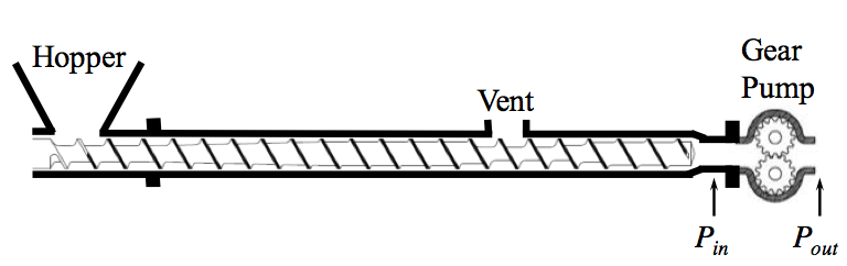
Their new one in the Infinite Build Demonstrator (H2000) has a ridiculously long melt section, a very long metering section (probably 8x D) and a very small diameter, it looks like 12 or 14mm maximum.
They list the throughput as 10x as high as a fortus 450mc (2.000 micro in³ / sec in the fortus vs 20.000 in the screw extruder) According to this video
[youtu.be]
Although i believe they got their units wrong as 2.000 µin³/sec does not convert to any sensible extrusion rate. if they indeed mean cubic microinches, that would convert 2000 µin³/sec to 3.28x10^-14 cc/sec or 1.18x10^-10 cc/h, which is just silly. If by micro cubic inch they meant 1/1.000.000 of a cubic inch, then that would mean 0.002 in³/sec, or 0,0328 cc/sec or 118 cc/h (for the fortus). For the infinite build that would mean 1181 cc/h. They really have to get their units checked out.
The speed of the infinite build demonstrator, they say it prints at 2m/sec and corners at 4g´s. I don´t really know what they mean by corner, that is also a pretty funky term. If they mean the forces that the printhead experiences when going around a corner (depending on the speed) that would roughly equal to a diagonal acceleration of both axes, so i would say each axis has a 4g/root2 acceleration of 2.8g´s.
Now for the servo,
I am using a JMC iHSV57-30-18-36 rated for 36V and 180W. In Peak, it can output 3x the rated continuous power. Here is the link
[shop.cnc-technics.de]
They have a software for download which connects to the servo via a serial port emulator.They were quite easy to tune, and the new v600 version also has an autotune function.
I calculated my acceleration with the continuous output, which is a safe bet.
I originally estimated my Gantry to weigh close to 6kg. The servo has a max torque of 0.57 Nm up to 2000 rpm, and a max rpm of 3000rpm.
With my 20/72 tooth reduction and a belt gear radius of 15.35mm, i calculated a peak force of 133N, which theoretically could accelerate a 6kg gantry (F=m*a) with 22.3 m/s² or 2.2g. My actual gantry of 3.5 kg could therefore be accelerated with 3.7g´s. (not accounting for friction of course)
I have tested up to 1.3g´s with no problems until now, but at that point my bed holders started vibrating as they were only made of 2mm titanium. At some point in the future i want to replace them with 6mm stainless which should eliminate that problem.
The belt conveyor system should eliminate that problem completely as it can be rigidly mounted.
The top speed is a direct result of the chosen speed reduction, if i go for max acceleration, the servo will quickly run out of rpm´s. I have calculated with my 20/72 reduction, 20 tooth pulleys with 5mm pitch belts and the 3000rpm servos that I could reach 1389 mm/sec.
JMC also has a 400w variant of this servo, which i probably plan on using for running the Y gantry, and then the 180w variant for mounting on the gantry to run the X axis. they also have lower power variants with 140 and 100 watts.
Generally servos will be a big must have as steppers just can´t run that fast, they would need extremely high voltages to switch the coils that quickly.
But on the topic of Odrives, yes i know them but i did not really consider them. First there is the price- you´re easily going to spend 260+ € to get all the components for one system. Then there is the issue of the separate encoder that has to be mounted perfectly centered on the shaft by the user (big no no) and the biggest no no for me was that you have to 3d print the housing for the servo. This will not hold up in any sort of continued high stress industrial environment and if you calculate a milled housing for it on top, plus the housing for the PCB, yo´re already in industrial AC servo price range, especially considering you also need a power supply with adequate size.
Siemens has a nice 400W AC servo for just 410€ where you do not even need a separate power supply.
Siemens Servo
So the Odrive really only makes sense when you can´t have standard servo housings or you want to integrate the motor into some other thing that shows space constraints (or already have a special brushless motor mounted somewhere)
Not really practical for the use that we intend for them.
Edited 6 time(s). Last edit at 04/08/2019 05:16PM by NitroFreak.
I totally missed the "metering" part, it is true that the fabbaloo article is talking about a gear pump. I only focused on their marketing video which only showed the reservoir. I thought this was the only new part.
gear pumps would be a great thing, if you can get the distance of the outlet of the pump to the tip of the nozzle as short as possible. Otherwise you have the same oozing problem again.
Although i think if i was to build an extruder that uses a gear pump, using a screw to melt pellets would make more sense than filament, as the filament was only really invented to make the extrusion apparatus more compact Theoretically it would also make it possible to turn the screw extruder by 90° and mount it parallel to the gantry "X" axis (I´m using X axis herein as the axis that runs parallel to the ganty).

If indeed the Bigrep guys use a gear pump, i would really like to know how they shrinked the part down, because these pumps are usually tool steel and quite sizeable. It will be hard to make the housing from aluminium and then use bronze bushings, if not impossible because the shaft would require an interference fit with the housing at room temperature to produce a slip fit at operating temperature.

Another,maybe easier method would be to install a pressure sensor near the nozzle to monitor the nozzle pressure. Then, instead of specifying extrusion length, you could just map extrusion pressure to the desired print speed. This would also make linear advance for high accelerations very easy to tune.
It would have to be tuned for every type of filament because of varying viscosity, but would enable a lot of control over the extrusion process. This would also enable high(er) speed extrusion of TPU material. Stratasys holds a patent for a similar concept, see here
[patents.google.com]
I think you will definitely have to go towards a metered pellet type screw system, otherwise printing 500cc/hour, even with the biggest spools, will not get you printing through the night.
I think the ideal setup would be a weight optimized gear pump coupled with a screw that continuously feeds material into a reservoir. The reservoir should ideally be "flexible" in size, accommodating a short overfill due to low speed geometry.
To limit the height of the apparatus, maybe it would be possible to use multiple shorter screws instead of one longer one to supply the molten plastics.
I have found these
[www.robotdigg.com]
I believe it is from the UPE from Mahor. They have 8mm in diameter and are 80mm long, (https://mahor.xyz/es/producto/pellet-extruder-v3/)
Now, if one wanted to omit the gear metering section, i think it would also be possible with an extrusion screw that has a very long metering section, in the order of 10x diameter. this should already enable really precise metering and quick changes in extrusion quantity when accelerating.
Stratasys has an old patent on a screw extruder here [patents.google.com]
Their new one in the Infinite Build Demonstrator (H2000) has a ridiculously long melt section, a very long metering section (probably 8x D) and a very small diameter, it looks like 12 or 14mm maximum.

They list the throughput as 10x as high as a fortus 450mc (2.000 micro in³ / sec in the fortus vs 20.000 in the screw extruder) According to this video
[youtu.be]
Although i believe they got their units wrong as 2.000 µin³/sec does not convert to any sensible extrusion rate. if they indeed mean cubic microinches, that would convert 2000 µin³/sec to 3.28x10^-14 cc/sec or 1.18x10^-10 cc/h, which is just silly. If by micro cubic inch they meant 1/1.000.000 of a cubic inch, then that would mean 0.002 in³/sec, or 0,0328 cc/sec or 118 cc/h (for the fortus). For the infinite build that would mean 1181 cc/h. They really have to get their units checked out.
The speed of the infinite build demonstrator, they say it prints at 2m/sec and corners at 4g´s. I don´t really know what they mean by corner, that is also a pretty funky term. If they mean the forces that the printhead experiences when going around a corner (depending on the speed) that would roughly equal to a diagonal acceleration of both axes, so i would say each axis has a 4g/root2 acceleration of 2.8g´s.
Now for the servo,
I am using a JMC iHSV57-30-18-36 rated for 36V and 180W. In Peak, it can output 3x the rated continuous power. Here is the link
[shop.cnc-technics.de]
They have a software for download which connects to the servo via a serial port emulator.They were quite easy to tune, and the new v600 version also has an autotune function.
I calculated my acceleration with the continuous output, which is a safe bet.
I originally estimated my Gantry to weigh close to 6kg. The servo has a max torque of 0.57 Nm up to 2000 rpm, and a max rpm of 3000rpm.
With my 20/72 tooth reduction and a belt gear radius of 15.35mm, i calculated a peak force of 133N, which theoretically could accelerate a 6kg gantry (F=m*a) with 22.3 m/s² or 2.2g. My actual gantry of 3.5 kg could therefore be accelerated with 3.7g´s. (not accounting for friction of course)
I have tested up to 1.3g´s with no problems until now, but at that point my bed holders started vibrating as they were only made of 2mm titanium. At some point in the future i want to replace them with 6mm stainless which should eliminate that problem.
The belt conveyor system should eliminate that problem completely as it can be rigidly mounted.
The top speed is a direct result of the chosen speed reduction, if i go for max acceleration, the servo will quickly run out of rpm´s. I have calculated with my 20/72 reduction, 20 tooth pulleys with 5mm pitch belts and the 3000rpm servos that I could reach 1389 mm/sec.
JMC also has a 400w variant of this servo, which i probably plan on using for running the Y gantry, and then the 180w variant for mounting on the gantry to run the X axis. they also have lower power variants with 140 and 100 watts.
Generally servos will be a big must have as steppers just can´t run that fast, they would need extremely high voltages to switch the coils that quickly.
But on the topic of Odrives, yes i know them but i did not really consider them. First there is the price- you´re easily going to spend 260+ € to get all the components for one system. Then there is the issue of the separate encoder that has to be mounted perfectly centered on the shaft by the user (big no no) and the biggest no no for me was that you have to 3d print the housing for the servo. This will not hold up in any sort of continued high stress industrial environment and if you calculate a milled housing for it on top, plus the housing for the PCB, yo´re already in industrial AC servo price range, especially considering you also need a power supply with adequate size.
Siemens has a nice 400W AC servo for just 410€ where you do not even need a separate power supply.
Siemens Servo
So the Odrive really only makes sense when you can´t have standard servo housings or you want to integrate the motor into some other thing that shows space constraints (or already have a special brushless motor mounted somewhere)
Not really practical for the use that we intend for them.
Edited 6 time(s). Last edit at 04/08/2019 05:16PM by NitroFreak.
|
Re: Millennium Peregrine – High Speed Large Format 3D Printer Project - Detailed Build Diary April 17, 2019 09:16PM |
Registered: 6 years ago Posts: 26 |
Max,
I am also very curious what clever solution BigRep cooked up for metering. I have experience with gear pumps like the Zenith BB PEP for metering hot melt adhesive, however as you mention these pumps are made out of big chunks of steel and very heavy. Micro gear pumps with tiny gears are used for room temperature metering of chemicals for medical applications, ink, and microfluidic systems - but I could not find an example that is made to handle the elevated temperatures and pressures needed for thermoplastic extrusion. It seems like it would be possible to manufacture a tiny gear pump using precision steel gears and custom housing? I looked for something we could reapply from small internal combustion engines but did not have luck.
We have looked at a number of pellet extrusion options, however the versions we have explored are heavy and add much more mass to accelerate on the gantry vs a simple filament extruder. One driver of weight is the screw diameter which I believe is driven by the fit of pellets into the helical channels in the screw. What kind of pellets do they run with the 8 mm robotdigg screw - this looks too small to handle many of he pellets I am familiar with?
Thanks for sharing the JMS servo. This looks very capable for the money. We have been playing with some 70V SureStep STPMTRH-23079 stepper motors from AutomationDirect that seem capable on paper, but we have not pushed these at the limit to confirm if these will achieve calculated dynamic performance.
Cliff
|
Re: Millennium Peregrine – High Speed Large Format 3D Printer Project - Detailed Build Diary April 19, 2019 01:48PM |
Registered: 5 years ago Posts: 207 |
Cliff,
I have been eyeing small hydraulic pumps.
[www.ebay.de]
This is a 1.1 cc/rev version that i found, but there are new ones for sale that go as low as 0.26 cc/rev. Depending on the material, it would be possible to use the gears in one of those and remake the housing and bushings to cope with the temperatures. Maybe, if it were just used for PLA or ABS, a normal aluminum housing would work fine.
For your target 500cc/hour , this would mean 0.12 revolutions per second for the 1.1cc version. The 0.26 cc version would be preferable as it would result in 0.53 revolutions per second at 500cc/hour.
I think these would be sufficiently light to use in a high speed gantry. Although "too heavy" is a relative term as the gantry just has to be sized accordingly to the weight of the extrusion head.
the 8mm robotdigg uses standard pellets. I just think that the melt zone is a bit short, hence the idea to use multiple.
The Stratasys uses some sort of micropellets. But this is of course because they want their customers to have to buy the pellets through them.
Geba sells micropellets for example. [www.geba.eu]
Max
|
Re: Millennium Peregrine – High Speed Large Format 3D Printer Project - Detailed Build Diary April 20, 2019 10:02PM |
Registered: 6 years ago Posts: 26 |
One very surprising discovery from our extrusion force testing data is the very high pressure generated when pushing against a 2.0 mm dia piston! At our target filament feed rate of 66.5 mm/s, our testing indicated approximately 34 lb of force is required to push fully molten 1.75 mm ABS filament through a 0.4 mm nozzle using a 2 mm piston. The corresponding extrusion pressure is approximately 7000 psi (483 Bar). The filament extruder is an incredibly capable high pressure pump with a continuously replenished piston. See the Extrusion Pressure vs filament speed graphs attached below.
A Zenith BB PEP Gear Pump used for plastic extrusion is only rated for 4800 psi (331 Bar). Your hydraulic pump looks like a great donor for gears, however it is rated for 230 Bar. Maybe multiple stages could be used in series to generate the pressure?
At 1500 mm/s filament speed we observed extrusion pressure of 23000 psi to force 1.5 mm ABS through a 0.4 mm nozzle. This is approaching water jet cutting pressure (just a lower flow rate)!
|
Re: Millennium Peregrine – High Speed Large Format 3D Printer Project - Detailed Build Diary April 20, 2019 10:21PM |
Registered: 6 years ago Posts: 26 |
Max,
The micropellets are really interesting! At only 0.4 mm size, these could fit into a small lightweight screw that might be a better fit for the scale of a RepRap machine. I wonder if a 3 - 5 mm dia screw can generate 500 Bar at these flow rates?
Here is pulverized ABS approx 0.25 mm particle size. [www.filabot.com]
SLS printers use Nylon powder. Here is PA12 at 0.06 mm particle size. [shop3dchimera.com]
It seems it could be straightforward to air convey plastic powder / micro pellets through small tubing. While the plastic powder could absorb moisture quickly, I bet it also could be dried rapidly if a dryer is included with the system. I would be concerned about safety and would want to make sure the powder is contained and not inhaled.
Thanks for a great conversation - I will think about this some more!
Cliff
Edited 1 time(s). Last edit at 04/20/2019 10:22PM by CinciCliff.
|
Re: Millennium Peregrine – High Speed Large Format 3D Printer Project - Detailed Build Diary April 21, 2019 11:08AM |
Registered: 5 years ago Posts: 207 |
There would probably be a lot to gain from optimizing the nozzle design. At the moment, it really only is dictated by the geometry of the drill that made the 2mm hole, together with the drill that made the 0.4mm hole. Optimized venturi designs can offer big throughput advantages, but would require us to make custom drill bits with the desired shape at the front.
Cliff, i just went over the maths and you never really need to push the filament at 66.5mm/sec through a 0.4 nozzle. At your target 1m/s, with a 0.4 nozzle and 0.2 layer height, your extrusion speed would be 33 mm/sec which would correspond with an extrusion force of 4700 psi or 324 bar.
Your targeted 66.5mm filament feed would only be necessary for the 0.8 nozzle, as you´ve said. This would result in a 3700 psi or 255 bar extrusion force. But still 33mm/s is very high and will cause a lot of friction and shear strength losses, especially over that long of a length that is necessary to melt it at that speed. Even the Fortus extrusion tips, that also have a heated length of roughly 70mm, do not enable the fortus to print at those speeds.
I think the gear pump rating at 230 bar is not of importance for us, as that has probably more to do with the seals not exploding. Since we would only use it as a donor for the gears, we have to make our own housing anyway.
If you have the time go and get a bit of ABS filament from the fortus machine, and run extrusion tests with that. Their ABS (SABIC MG94) has a very high melt flow rate. I also have it here and you can feel the difference vs lower quality ABS filament, when you push it manually through the nozzle.
I also remember from the Formnext event that there was a filament maker that had an unusual nanodiamond filled PLA- i can´t remember its name, but here is a similar product
[carbodeon.com]
They listed the printing speed as up to 500mm/s- thanks to the increased thermal conductivity which enables the PLA to melt quicker. Maybe that is worth a test?
I don´t know about using milled or pulverized powder, because the milling process probably severely degrades the polymers. Also, non- spherical particles and powders tend to jam up in hoppers, unlike actual spherical pellets.
For a miniaturized screw extruder it is probably important to use micropellets, if just for the sake of homogenity. It is true that if just three pellets fit into the screw passage, you probably cant expect a consistent extrusion.
Hence why Stratasys is probably using such a long screw paired with the micropellets.
I am currently in contact with Solvay, maybe they can supply their PPSU as micropellets? I have seen that they offer their PEEK as a powder.
Happy Easter
Max
Edited 1 time(s). Last edit at 04/21/2019 02:20PM by NitroFreak.
Cliff, i just went over the maths and you never really need to push the filament at 66.5mm/sec through a 0.4 nozzle. At your target 1m/s, with a 0.4 nozzle and 0.2 layer height, your extrusion speed would be 33 mm/sec which would correspond with an extrusion force of 4700 psi or 324 bar.
Your targeted 66.5mm filament feed would only be necessary for the 0.8 nozzle, as you´ve said. This would result in a 3700 psi or 255 bar extrusion force. But still 33mm/s is very high and will cause a lot of friction and shear strength losses, especially over that long of a length that is necessary to melt it at that speed. Even the Fortus extrusion tips, that also have a heated length of roughly 70mm, do not enable the fortus to print at those speeds.

I think the gear pump rating at 230 bar is not of importance for us, as that has probably more to do with the seals not exploding. Since we would only use it as a donor for the gears, we have to make our own housing anyway.
If you have the time go and get a bit of ABS filament from the fortus machine, and run extrusion tests with that. Their ABS (SABIC MG94) has a very high melt flow rate. I also have it here and you can feel the difference vs lower quality ABS filament, when you push it manually through the nozzle.
I also remember from the Formnext event that there was a filament maker that had an unusual nanodiamond filled PLA- i can´t remember its name, but here is a similar product
[carbodeon.com]
They listed the printing speed as up to 500mm/s- thanks to the increased thermal conductivity which enables the PLA to melt quicker. Maybe that is worth a test?
I don´t know about using milled or pulverized powder, because the milling process probably severely degrades the polymers. Also, non- spherical particles and powders tend to jam up in hoppers, unlike actual spherical pellets.
For a miniaturized screw extruder it is probably important to use micropellets, if just for the sake of homogenity. It is true that if just three pellets fit into the screw passage, you probably cant expect a consistent extrusion.
Hence why Stratasys is probably using such a long screw paired with the micropellets.
I am currently in contact with Solvay, maybe they can supply their PPSU as micropellets? I have seen that they offer their PEEK as a powder.
Happy Easter
Max
Edited 1 time(s). Last edit at 04/21/2019 02:20PM by NitroFreak.
|
Re: Millennium Peregrine – High Speed Large Format 3D Printer Project - Detailed Build Diary April 21, 2019 02:34PM |
Registered: 5 years ago Posts: 207 |
One more thing that just came to mind is, you can check for the additional extrusion force necessary by the long melt zone by doing the extrusion tests without the nozzle. That way you will also notice relatively quickly if the filament is coming out the other side unmolten.
Maybe it would also be worth checking if the 2mm rod has a noticeable drag on the sidewalls (with residual polymers sticking to the wall) when pushing filament through. One idea that came to mind was to make a piston, where only the head is of 2mm diameter, and the rest of the body is maybe 1.5mm diameter.
Sounds hard to make, but one idea would be to take a 1,5mm rod, and hammer the end flat so that it has a 2.5 mm diameter end, then turn it down on the lathe to 2mm.
|
Re: Millennium Peregrine – High Speed Large Format 3D Printer Project - Detailed Build Diary May 17, 2019 07:14PM |
Registered: 4 years ago Posts: 2 |
It would seem that if you want to create an extruder that can exert more force on the filament without skipping, then you would want to increase the amount of contact area between the extruder drive mechanism and the filament.
If you think about the similar analogy with vehicles, you can decrease the chances of the vehicle losing grip of the road by either using larger tires, by using more wheels, or by using tank-treads instead of wheels.
You can do all the same with extruders:
1) Larger diameter drive gears. The larger the diameter, the greater the contact patch with the filament.
To avoid losing torque, you would still use a gear on the motor to turn the drive gear.
1a) Larger diameter drive gear in combination with multiple (smaller) idler gears.
Who says you only need one idler gear to push the filament against the drive gear? Since the filament is flexible, you can use multiple idler gears pushing against the drive gear.
2) Multiple (pairs of) drive gears. This is pretty straightforward. The downside is that you need several gears to drive all the drive gears in the same direction.
3) Tread drive: each drive gear turns a tread of some sort, and multiple idlers push the treads against the filament from either side.
These are listed in order from simplest to most complex. I also imagined other possibilities, such as something similar to the feed dogs on a sewing machine.
But I think that one of the simpler ideas should be enough.

Sorry, only registered users may post in this forum.