Biceps, a two headed 3D printer
Posted by leadinglights
|
Biceps, a two headed 3D printer July 18, 2019 12:33PM |
Registered: 12 years ago Posts: 1,450 |
This is sort of a build log of the last stages in the development of a twin headed printer with a heated enclosure, vacuum hold-down build stage, kinematic mounted build stage and two water-cooled print heads with automatic filament purge and nozzle wipe between each head change.
The printer is a cartesian type with the build stage moving in both X and Y while the print heads move only in the Z direction. Print heads are swapped out so that only trivial adjustments of X, Y and Z need be done by the printer firmware.
This printer has existed in many stages, some parts have been made and used while others exist only in the imagination of TurboCAD. The frame has been used as an engraving/light milling machine and as a proof of concept for extremely sensitive piezoelectric sensors. The name of the printer is Biceps, Latin for "Two headed".
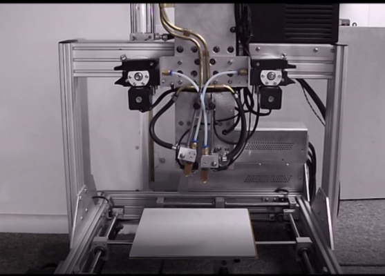
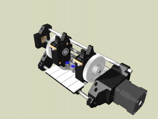
A view of the printer showing the toggle heads. The DC motor in this picture has been subsequently replaced with a stepper motor. A video of the toggle operating can be seen on [www.youtube.com]
Present project status.
Many parts are working well. The framework is good and accurate although, if I knew then what I know now, I would have increased the ground rods from 10mm and 8mm diameter to 12mm and 10mm diameter to reduce the small sag and elasticity. The vacuum build stage is now able to reliably hold a vacuum and the kinematic is able to return after a disturbance to within 3 microns. The piezo sensors now also have a repeatability of better than 3 microns.
The head changing mechanism was accurate until I found that 3D printed gears are a bit fragile so is now being redesigned to use Huco Acetal gears - this would be easier if they were available in the sizes that I want.
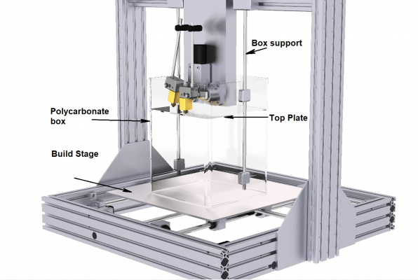
The heated enclosure is the only part that exists still only in CAD
Apologies for this CAD rendering but the heated enclosure does not yet exist.
The history – Polyceps (many heads)
The dual headed mechanism is the final fall back position from what started as a seven headed monster including four print heads, two pick and place heads and a head to spray liquids such as adhesives or dyes during the print. The frame only of this printer was ever built: Converting the CAD blocks into realizable specifications came up against strength of materials, availability of gears and bearings and many other problems – a less gung-ho approach was obviously needed. The existing frame, which after all is simply an XYZ mechanism, was used in all subsequent developments.
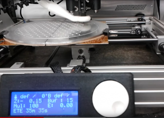
Milling a vacuum hold down heated bed for a delta on the 3D printer frame.
A PCB machined on the printer. 3Mm square IC with 6 pins. 0.2mm isolation lines demonstrating that the XY mechanism has very little play.
Re-casting my ideas to a five head printer I did get as far as building a mechanism with one motor for all five extruders, a second motor to switch between active heads and a solenoid to lift the heads for position changing. Mechanical fragility and repeatability caused major problems while software to align the gears so that they would mesh correctly when changed finally killed this one.
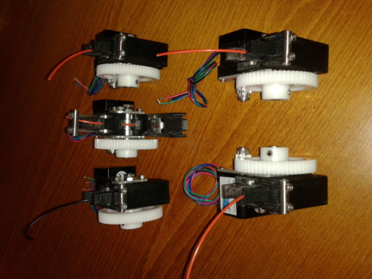
Five extruders made for the above printer. These have been used for all subsequent iterations including Biceps.
A second iteration of the five head design used five identical extruders with three of them feeding the hotends through short Bowden tubes. As the software was beyond my capabilities I paid for some development work. The less said about this the soonest mended - suffice it to say, if I can’t program it myself in assembler then it ain’t going to happen! For a while the frame was used as milling machine to make vacuum stages for other printers, PCBs and other light duties.
CAD rendering of one of the many 5 head combinations tried. This one has two direct drive extruders for Bowden sensitive materials. The other three feed filament through 250mm long Bowden tubes
Biceps
After the project had languished for a couple of years I needed the space and I had to choose what to throw out. In the end I sent my trusty Prusa type printer 'Caliban' to what I hope is a good home and resurrected Polyceps as Biceps. The hope here is to get a very rapid head change along with sufficient stability that filament in the inactive head can be changed and the nozzle purged and wiped to allow the nozzle to be presented clean after changing filament. Other technologies would be carried through including the water-cooled hotends and the vacuum hold-down used on my Delta printer. The software problems go away as M and G codes are easy to understand as the codes I need already exist and I don’t need to rely on anybody else for this bit
Early attempts at a change mechanism used a DC motor with a gearbox but repeatability prove very poor and resulted in a redesign using a NEMA11 stepper motor. With the new motor and gearbox nozzle returns to the same position within measurable limits (ca 3 microns)
The kinematic mechanism and piezo sensors did pretty much everything they should and the extruders and watercooling are now well proven in earlier trials
Present work
The head changing mechanism gear problem mentioned above is ongoing. New gears have been ordered but will need to have some teeth removed to fit into the framework.
The vacuum hold down is proven but is a lash-up. The vacuum pump is now a small one which switches on only as necessary to keep a good vacuum – about 1 to 2 seconds of pumping per minute. A solenoid which is to be normally open and inexpensive seems to be unavailable – several that solenoids that I have bought are not satisfactory so I am making a new one.
Vacuum, heated bed power lines, thermistors and power and signal to the piezo signal conditioner board have to be got to the build stage (bed) . Variations of cable drag chains have been tried under the bed but this seems to be complex, heavy and snag prone. The most satisfactory answer seems to be simply a conduit hanging down to one side of the bed.
The Heated enclosure so far exists only as some speculatively purchased plastic sheets to check for warping when hot. The purge and wipe exists at the moment only as a guess that there is enough room and a hope that it wont be too hard.
If anybody has any use for any of the ideas here they are most welcome to them. I will endevour to occasionally come back to this thread to report on any progress.
Mike
Edited 1 time(s). Last edit at 07/18/2019 02:49PM by leadinglights.
|
Re: Biceps, a two headed 3D printer July 24, 2019 08:51AM |
Registered: 9 years ago Posts: 204 |
|
Re: Biceps, a two headed 3D printer July 24, 2019 09:14AM |
Registered: 12 years ago Posts: 1,450 |
Quote
Shank man
.................................................................................................................... Is the purpose of having a vacuum hold down to allow a quick change out of the build plate?
That is the main reason. Video at [www.youtube.com]
There are several less important reasons such as not having to worry about it if the print surface sticks too firmly- just cut off the excess.
The vacuum hold down works beautifully on PLA but not too good on ABS due to the bad edge curl with ABS. This is the reason that this has a heated enclosure.
Mike
|
Re: Biceps, a two headed 3D printer August 07, 2019 04:35PM |
Registered: 12 years ago Posts: 1,450 |
Since my previous post there have been some good successes along with some false starts which have taken a lot of time to resolve.
On the piezo sensors I am now almost at the point of declaring that 1 gram of pressure and 1 micron of post contact travel had been achieved. Repeatability is a bit more like 3 microns although that is of the order of variation caused by random breezes causing local expansion/contraction.
View below is of the XY carriage showing the three piezo mounts and the signal conditioning PCB. Also visible is the black silicone tube of the vacuum connection and the heater which consists of Nichrome wire in a PTFE tube laid in a track machined on the lower surface of the build plate.
One of my most import changes was to make the vacuum hold-down more practical: I have been using a vacuum pump with a 1/4HP motor running continuously and have intended to fit something with a much smaller vacuum pump that only runs when necessary to maintain the vacuum. The first problem I found with my new pump is that most plastic films squirm about like one of those "fortune telling fish" found in cheap Christmas crackers when put on a 100°C plate. With the big old pump this was not a problem as the film was pulled down with a snap and had no chance to squirm but the little pump did not move enough air to do this. The solution was to pull a vacuum in a reservoir and only connect this to the hot plate as plastic film is put on the plate.
Another problem was in getting the vacuum, the heater power and thermistor wires and the wires for the piezo sensors to the XY carriage. The original design was to have two drag chains, one from the static framework to an intermediate carriage and one from there to the XY carriage. This approach was problematic in almost every respect but the killer was that drag chains on sufficient size to carry the vacuum tube as well as the wires took up more space than I had allowed. Using a single drag chain from the frame to the XY carriage was rejected when I found that the largely unconstrained chain swung about in an unpredictable manner.
The solution to this problem was to simply have the wires descending from a slider block to one edge of the XY carriage. The longest part of the run in stiffened with a thin wall stainless steel tube which also forms part of the vacuum line. This was less than half of the moving mass of either of the cable chain arrangements although I will admit it is a bit ugly
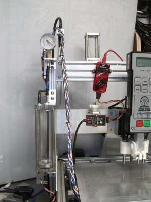
The view below shows the vacuum and cable connections. The perspex cylinder on the left is the vacuum reservoir with a vacustat (diaphragm and microswitch) on the bottom.
I am still having a bit of a problem as I haven't been able to source a good normally open solenoid valve with very low flow restriction – at the moment I am providing a manual valve action by kinking a section of the vacuum tube to empty the reservoir until the new plastic film is fitted. Once I have that sorted out I will use it to update the vacuum hold-down I have on my old Delta printer
Mike
|
Re: Biceps, a two headed 3D printer August 24, 2019 06:01AM |
Registered: 12 years ago Posts: 1,450 |
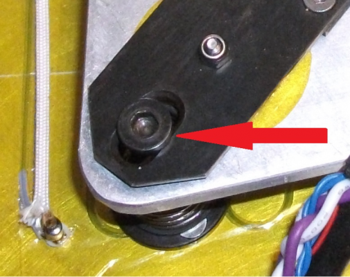
I found a new and interesting problem with the kinematic mount. When the bed was heated it would expand and each of the screws would move outwards along its slot - away from the common centre. The problem came in that the friction between the head of the adjusting screw and the chamfered slot gave rise to stick-slip behaviour during heat-up resulting in the middle of the bed rising and falling by up to 50µm. The slot is shown below
The immediate solution was to tap the bed with the nozzle or a convenient hand tool - like tapping a sticky gauge. Lubricating the chamfer with extreme pressure grease (Millers MPF2) seems to work but only time will tell how long the lubricating film lasts.
Mike
The immediate solution was to tap the bed with the nozzle or a convenient hand tool - like tapping a sticky gauge. Lubricating the chamfer with extreme pressure grease (Millers MPF2) seems to work but only time will tell how long the lubricating film lasts.
Mike
|
Re: Biceps, a two headed 3D printer October 17, 2019 11:48AM |
Registered: 12 years ago Posts: 1,450 |
Another report on the Biceps printer.
The fix for the slight distortion caused by the friction of the parts of the kinematic mount (see previous post above) seems to be good. Having said that, having to re-lube an almost inaccessible part - albeit only every year or so, is a bit of a drag so I am looking at slight design changes to incorporate a low friction part.
The vacuum does exactly what it should, silently and without fuss. When I get a chance I will modify my other printers to use the same vacuum work holder.
The bed leveling conditioner is giving the most problems. Although it is very sensitive it was intended that the conditioner would discriminate bad contact signals such as external mechanical or electrical noise or the signal from a nozzle with plastic or dirt on it. The problem comes with rejecting noise: Mechanical noise from things dropping on the bed can be detected and it is even possible to tune the response so that it rejects almost all external noise - but this can only be done with one part of the bed - typically the centre. Blunting the response characteristic so that all good contacts will be reported increases the number of false positives and the sensitivity to general mechanical noise being a lot less good than hoped.
The main part of the duty of the conditioner, reporting dirty nozzles, seems to be pretty reliable at detecting the plastic deformation signal with more than about 25µm of molten crud or 50µm of dry plastic. Even at this though it is not as great as hoped as some surfaces, notably blue paper, have more variation of height and compliance than any reasonable dirty nozzle limit.
Of the other main new bits of Biceps, the twin head toggle mechanism is redesigned and waiting for the conditioner to be resolved one way or another. I have managed to narrow down the reasonably achievable temperature of the mini-enclosure to better than 70°C but struggling at 80°C
Mike
|
Re: Biceps, a two headed 3D printer October 15, 2020 11:00AM |
Registered: 12 years ago Posts: 1,450 |
Biceps is beginning to emerge from nearly a year in the wilderness. This was partly because I came across a problem with the design of the underbed sensors which needed several months of head-scratching. Besides this though, there was at least a degree of concern that documenting my build may be shouting into the wilderness with my words only read by netcrawling bots or the occasional dyslexic Google searcher. In the end though, there is only so much entertainment to be had in fretting about Covid 19 or the shortcomings of damn-fool politicians, so I have returned to the fight. On the practical side though, writing a bit of a build log is a good discipline for getting orderly documentation.
The most noticeable changes so far are in the toggle mechanism. The gears were previously 3D printed but were prone to cracking so have been replaced with commercial Acetal gears. Nothing with the needed shaft diameter(s) was available so they had the bosses replaced with steel hubs. These are the three gears on the bottom of the mechanism.
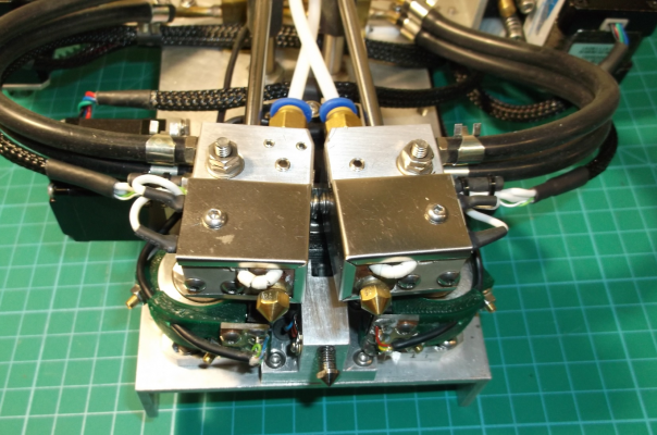
The three underbed sensors have been replaced with a single one on one of the bed mounts. This provides information on the true Z positions of both nozzles but only used with the nozzle positioned directly above the mount. For bed leveling, I now use a piezoelectric touch sensor which can gather data for bed leveling and compensation. The touch sensor can be seen between the two nozzles which are both in their halfway retracted position. Both the underbed piezo and touch sensor have a resolution of substantially better than 1 micron
The touch sensor has its own conditioner as the signal from this is somewhat different to the signal from an underbed piezo.
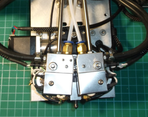
The toggling function had been powered by a DC motor but I have replaced this with a NEMA11 stepper motor and worm gearbox. This can be seen below - though somewhat obscured by the two printheads.
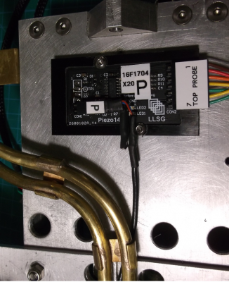
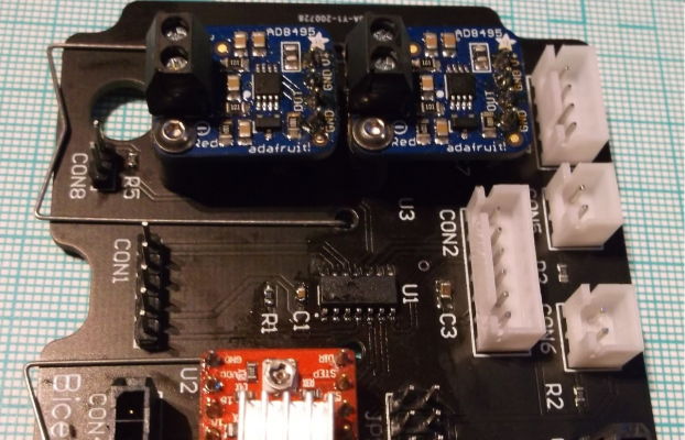
The toggling of the heads is controlled by a Microchip PIC16F1824 MCU and a familiar Pololu stepper motor driver. PIC is the center of the PCB shown below. The PCB is shared with two Adafruit thermocouple conditioners for the hotend temperatures.
There has been some other progress. The heated chamber is better and can just about get to 80C and an addition will be an optical sensor to measure X and Y offsets. Most of the other work has been in getting drawings and circuits together which I may attach as a zip file.
I will try to keep this updated a bit more often than once a year. I have no chance of equalling MechaBits with his Kraftwerk'r log but then I have no Shrooms to keep me going.
Mike
Mike
|
Re: Biceps, a two headed 3D printer October 18, 2020 02:49PM |
Registered: 12 years ago Posts: 1,450 |
The last couple of days has been spent sorting out the wiring and making sure the documentation is up to date.
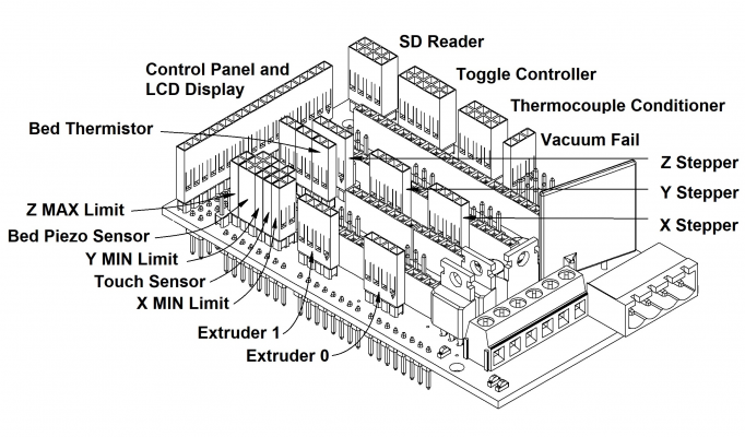
The RAMPS 1.4 is getting a bit crowded in its housing and will be fitting homemade oversized heatsinks to get the heat from the motor drivers where the fans can cool them Something I didn't think of untill I thought "where are the Pololus?"
Connection diagram to show what the RAMPS is controlling.
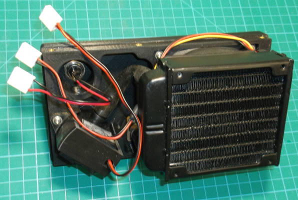
There is more pretty dense wiring in the auxiliary box. This space gets shared with a water pump and radiator - See bottom picture: This is a bit worrying but I am keeping to parts and methods used in water cooling in computers.
And again a diagram to show the connections
The next few days will be spent on the cooling system.
Mike
|
Re: Biceps, a two headed 3D printer October 20, 2020 10:38AM |
Registered: 12 years ago Posts: 1,450 |
The present stage of the project is to determine how good the water cooling is. When I first started this project I designed a water cooled cold-end and did some simple trials to assure myself that it was satisfactory. The notes having been lost I think that a bit more disciplined approach worthwhile.
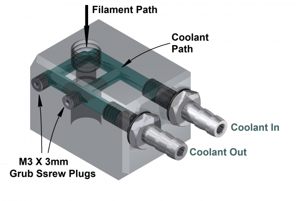
The diagram below shows one of my water cooled cold-ends. The aluminium body has bee ghosted to show the coolant path picked out in green: In and out manifolds are 3.3mm diameter and the cross galleries are 2.5mm diameter.
The main tests will be to monitor the temperature difference between the coolant inflow and outflow and also the temperature of the cold-end body and the hotend body. I have seen some indication that more heat is transferred through frequent filament retractions than gets through the heat break - hopefully I will be able to confirm or deny this.
Another test is to find if the radiator is correctly sized. I think it is probably overkill, early tests and some thermal analysis showed that it was O.K. for 5 hotends. It is possible that it could be replaced with a simple spiral of copper tube and a 40mm fan.
Mike
|
Re: Biceps, a two headed 3D printer October 31, 2020 11:06AM |
Registered: 12 years ago Posts: 1,450 |
The next bit of work on this printer is to try out the water cooling in printing conditions. I have already established that quite a bit of heat that the cold-end will be required to remove comes from hot filament being moved into the cold-end during retractions ( [reprap.org] ). As far as how much, checking this by manually extending and retracting filament gives a not very precise value of "quite a bit". To do any better I will at least need to do a dummy printing run with lots of filament movement - e.g., a print of the Eifel Tower.
What follows may be lengthy, but in the end the process is quite simple but to find out how did involve a lot of searching of the internet, head-banging-on-the-wall, and some requests for help from various forums. Repetier came through with flying colours and it is now almost trivial get ttwo independant thermocouples working and correctly calibrated.
My temperature sensors are 'K' type thermocouples with Adafruit AD8495 conditioners and analog output to A3 and A4 on the AUX3 port of a RAMPS board.
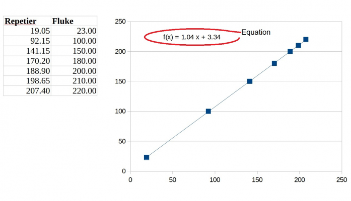
This worked as it should, but the calibration was a bit less than good: 100°C in the middle of the hotend gave 91.8°C on the Arduino while 220°C gave 207.4°C - not great! The output from the other side gave numbers only slightly better while a spare Adafruit board was somewhere in between. It was clear that some calibration tweaking was needed, but it was less than apparent how this could be done on Repetier Firmware. Careful reading of anything on Marlin Configuration and even asking on the RepRap Marlin subforum having resulted in no great understanding so it was back to what I can work with.
A query on the Repetier Firmware forum resulted in a conversation that ultimately led to a way of doing it.
Use the development branch of Repetier Firmware as older versions do not have this feature. Use Repetier-Firmware configuration tool for version 1.0.4 and make sure that EEPROM usage is set to EEPROM Set 1 as this allows the calibration values to be set for the hot-end(s)
On the 'Tools' tab, there is a tick box marked "Add linear and constant correction to temperature readings (TEMP_GAIN)" If this is ticked then there will be two settings that appear on the EEPROM.
Once the firmware has been compiled and uploaded you can use Repetier Host to connect and change the slope and offset for each of the hotends. In my case, these appeared as Extr. 1 Temp. Gain, Extr. 1 Temp. Bias, Extr. 2 Temp. Gain and Extr. 2 Temp. Bias.
There are many ways to get the numbers to plug into the gain and bias values but a quick route is to use a spreadsheet such as LibreOffice. I took several readings from the temperature in the middle of the hot part of the hotend - measured with a Fluke thermometer, and the readings reported by Repetier. These were charted with a scatter chart - points only then I selected and right-clicked one point and selected "insert trend line" and selected "show equation". The first number is the value to be inserted into Gain and the second into Bias.
The readings from Repetier and the Fluke thermometer are now within 1°C throughout.
Mike
|
Re: Biceps, a two headed 3D printer November 24, 2020 09:35AM |
Registered: 12 years ago Posts: 1,450 |
I had hoped to be able to get some early results of the new bed leveling/compensation method but have obviously annoyed the gods of technology - perhaps because I offered neither prayers nor sacrifice after everything I did had been going so well for a while.
Early indications of this were when I tried to open the assembler in the latest Microchip MPLAB X IDE and found that it didn't exist. The reason for this turned out to be that Microchip now only supports assembler as inline code in the C compiler. Even if I wanted to learn to use this it is a poor and emasculated thing compared to a real assembler. As an aside, I should explain that I am fluent in assembler for several different microcontrollers and microprocessors but have little aptitude for high-level languages. The various devices that I design use Microchip PIC16s or sometimes Texas MSP430 microcontrollers and maybe others. I solved this the only way that was left to me: I deleted the IDE and installed an earlier version and switched off auto-update.
Way back, when I first used a stepper motor to do the hotend switching, I found that there was an anomaly in the data: The number of steps travelling from one hotend to the other was not the same as it was when reversed. After a careful examination of everything I found that there were cracks in the 3D printed gears of the mechanism. The gears having been replaced with heavy duty Delrin parts, I got back to checking out the system only to find that the problem was unchanged. The nature of the problem is described below.
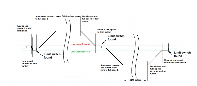
In order to check that each operational move has been completed correctly the controlling program counts the number of pulses between the limit switches in each direction during initialization. This number will be used to compare the number of pulses in operational moves to check for fault conditions such as missed steps etc.. The problem that exists is that the distance between limit switches is about 40 pulses longer on the reverse trip than on the forward trip and this applies regardless of whether the movement was clockwise followed by anticlockwise or anticlockwise followed by clockwise.
The diagram above shows the sequence of events. After an initial dance to get an accurate triggering of the first limit switch, the stepper accelerates from zero to full speed, runs at full speed for a predetermined number of pulses then decelerates to a low speed, and creeps forward to meet the far limit switch. The acceleration, full speed run, and creep to limit switch is then repeated in reverse. This sequence should account for such variables as backlash in the various gears, hysteresis in the limit switches, etc. The prime suspect is that the stepper is missing steps but changes in starting speed, acceleration, full speed, motor current, voltage (12V or 24V) have not shown any cause for concern.
Having nothing else to blame and grasping for straws I went straight for the prime suspect and ordered a more powerful stepper motor - a NEMA11 with a 51mm long frame and 0.12Nm of torque instead of the 32mm long 0.07Nm unit I first fitted. It was here the I discovered that something marked on eBay as "Dispatched from the U.K." and "Next day dispatch" can mean that it will be dispatched the next day from China then re-routed by the seller in the U.K. some 10 days later. To add insult to injury, Hermes mislaid the parcel resulting in another day to wait.
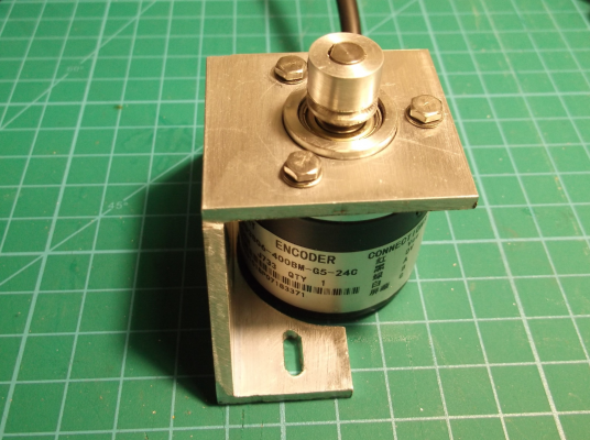
While waiting for this motor, I thought that it may be worth having a motor with shafts on both ends so that I could attach an encoder to actually see any missed steps. I found that Zapp automation (now called Motion Control Products) had such a beast and ordered one. The upshot of this is that the first stepper motor arrived half an hour ago and the second one will get here in about an hour.
O.K., so in the last nearly a month I have achieved not a lot. I am relieved only that the end of the twin plagues. the plague of Donald and the plague of Covid, are in sight. If my suffering over the last month has bought any pleasure to the Gods, I may also see the end of the plague of stepper motor.
Mike
|
Re: Biceps, a two headed 3D printer December 04, 2020 02:10PM |
Registered: 12 years ago Posts: 1,450 |
I have got the asymmetry down to 4 steps. This involved a complete strip-down of the gearbox, fettling of the gears to address a slightly high spot, re-greasing with extreme pressure grease instead of general purpose grease and, most importantly, the replacement of the stepper motor with a more powerful version. Nothing that I did should have cured the problem as things like an under-powered motor or tight spots on the worm gear should be random and not repeat from run to run or in either direction. Having said that, it is now much less and repeatable so can be corrected for. This error should not be there and nothing I know of can account for it, but, as Albert Einstein was wont to say, "bugrit, life is too short".
Late breaking news. I have been variously using Pickit3 and Pickit4s to debug this. With care and understanding of the system, it is usually possible to get reliable debug data, but apparently not in this case. If I disconnect the debugger from my controller and run it in a stand-alone mode, the timing difference goes away. I have confirmed this by connecting the stepper motor to a 400 PPR quadrature encoder then decoding the signals. I now get approximately 1 step of jitter, just where it should be.
A bit of detail about the gearbox. This was designed to fit on the same mountings as a common DC motor/gearbox but take a Nema11 stepper motor. The steel and brass worm and worm-wheel are 1 Module with 20 teeth on the worm-wheel - I had to turn both down on a lathe so that I could get them into a decent space. I 3D printed two sets of the gearbox casing: The first was made with a deliberately large worm to worm-wheel spacing so that I could measure the error and correct it on the second print. This worked well enough that the play is less than 0.05mm with gears dry. Some photos of the stepper and gearbox below.
If anybody thinks that they can use a gearbox like this I will put the STL and STEP files and drawings of the machined parts on Thingiverse. Be warned however that this will only be directly useful if you find the same worm/worm-wheel combination.
Mike
|
Re: Biceps, a two headed 3D printer December 16, 2020 02:16PM |
Registered: 12 years ago Posts: 1,450 |
Since the last post, I have been working on the software and hardware for the controller for the toggle mechanism to make it play nicely with the Arduino & Repetier firmware. I had already got the toggle mechanism to be repeatable to within ±3µm and to swap heads within 0.6 of a second. All the faults I have been able to think of are now detected by the software on the controller and Repetier Firmware will be paused until the fault is cleared. The toggle can now be commanded to take a halfway position for the Z probing to switch from an underbed sensor to find the height of both Z probes, swapping to a piezoelectric touch probe to map the bed.
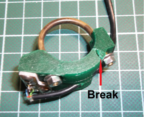
Despite the successes, I have been plagued by a sense of unease that none of the explanations for the asymmetry have been completely convincing: Although the asymmetry reduced and eventually disappeared, it seemed that this was might not have been because of the "improvements" but was happening entirely independently. During some adjustments to get the inherent positions of the two nozzles as close to the same as I could, I found that one of the limit switch carriers had developed a crack. This is shown in the photo below.
It is possible that the reason for the strange asymmetry is that the crack opened under the pressure of the microswitch in its operated position and closed slightly during the travel out and return. This is still not completely convincing as it only explains the problem if the broken holder is the one from which the trace starts and ends - but not where the broken carrier is the one visited between out and return journeys - though perhaps that will be obvious with a bit of thought.
I redesigned the switch carriers and they can be seen in the photo below. In order to stop this cracking again, I have incorporated a 1.5mm thick stainless steel plate for the nuts to bear against.
Mike
Edited 1 time(s). Last edit at 12/17/2020 02:05PM by leadinglights.
|
Re: Biceps, a two headed 3D printer January 01, 2021 02:15PM |
Registered: 12 years ago Posts: 1,450 |
The last two weeks have been somewhat frustrating with design changes necessitated by earlier modifications only becoming apparent as the printer moves towards its first tests. Changes in the Z lead screw to incorporate an anti-backlash nut resulted in a loss of 14mm in Z travel. The best way to fix this is by subtly redesigning the frame. The larger stepper motor for the toggle switch got in the way of the cable umbilical for the build stage and strengthened support for the end of the umbilical snagged one of the rail supports.
A problem with the software, or at least a problem that I didn't understand, led to several days being wasted with an installation of Repetier Firmware which appeared to break the motor control. In essence, I changed from Repetier 0.92 to the latest development version along with its newer configuration tool. I did this to take advantage of the linear slope and offset correction for thermocouples that Repetier has put in this. What I didn't know was that unless the EEPROM mode changed then the old EEPROM configuration would corrupt all sorts of things. The lesson from this is to read the instructions more carefully.
Otherwise, all seems to be going well. The toggle mechanism settles within 3um every time and the head change takes a little less than 0.6 of a second. Nozzle contact is detected cleanly and shows plastic or dirt on the nozzle predictably. The Z carriage mounted probe for bed leveling seems to work well although a little more programming work is needed there before I am completely happy. Some preliminary work has been done on the nozzle cleaners and purge gutters for the heads - I hope to be able to put some CAD renderings and/or photographs of this in the next few weeks.
Mike
Sorry, only registered users may post in this forum.
