DIY printhead
Posted by johnrpm
|
Re: DIY printhead August 08, 2010 05:22PM |
Registered: 13 years ago Posts: 406 |
Thanks for doing the wiki stuff, that really helps,
the line is thick because the head is at max power, the nozzle diameter is approx .2mm,
the drive electronics are very important to the head output, also the distance from the nozzle to workpiece and velocity of workpiece, ages ago when I dismantled an hp printer and told it to do a test print whilst holding the printheads by hand, I was amazed at the size of the spray that came out, I could take the head to work and get images of the hole perhaps?.
I have bought some electronic lighters from poundland, 5 in a packet, you get 5 piezo stacks, 5 refill valves, thay also have a blue LED and 3 button batteries in each, I have a feeling they are going to need higher voltage to drive them, maybe as much as 1000v,
I may be wrong but I feel that we are going to have to develop different heads for different application, but I really do feel that the drive electronics are the key.
|
Re: DIY printhead August 08, 2010 06:19PM |
Registered: 14 years ago Posts: 356 |
johnrpm Wrote:
-------------------------------------------------------
> the line is thick because the head is at max
> power, the nozzle diameter is approx .2mm,
> the drive electronics are very important to the
> head output, also the distance from the nozzle to
> workpiece and velocity of workpiece, ages ago when
> I dismantled an hp printer and told it to do a
> test print whilst holding the printheads by hand,
> I was amazed at the size of the spray that came
> out, I could take the head to work and get images
> of the hole perhaps?.
Since I am interested mainly on PCB printing, I would like to have 0.1mm line tick or at maximum 0.2mm. My objective is to be able to print 0.25mm tracks, for be able to use cheap ARM Cortex-M0/1/3 which have 0.5mm pitch - I believe actual electronics ICs and recent future will be with using the 0.5mm pitch or even 0.4mm.
I would prefer that you say/verify that 0.1mm line thickness can be done with this print head :-)
Can you make holes of 0.1mm? Do you think that with a 0.1mm hole we can get a 0.1mm line thickness? we can't get lower thickness lines than the hoke size, right?
> I have bought some electronic lighters from
> poundland, 5 in a packet, you get 5 piezo stacks,
> 5 refill valves, thay also have a blue LED and 3
> button batteries in each, I have a feeling they
> are going to need higher voltage to drive them,
> maybe as much as 1000v,
Hmmm, why not try to use/work with the "standart" piezos e can find on electronics components shops? like the ones Arduino users are using? like the ones I got on a local electronics components shops?
> I may be wrong but I feel that we are going to
> have to develop different heads for different
> application, but I really do feel that the drive
> electronics are the key.
Would be nice if we just had the same head and we just need to change the nozzle and adjust parameters to control the circuit electronics, like now happens with RepRap nozzles, which we can find in many sizes on market, from 0.25mm up to 1mm.
Please tell me what is the minimum hole size you can drill, because if is not enough, I can always ask to others producers of actual RepRap nozzles. By the way, why not make the housing to the piezo with a thread so we can attach actual M6 nozzles? -- would be perfect to change over various sizes of nozzles and because others could provide the nozzles to us :-)
John, do you have a RepRap Mendel or a RepStrap? can you print in 3D? -- what parts for this print head we could print in 3D?
---
New cutting edge RepRap electronics, ARM 32 bits @ 100MHz runs RepRap @ 725mm/s:
[www.3dprinting-r2c2.com]
|
Re: DIY printhead August 09, 2010 04:47AM |
Registered: 14 years ago Posts: 356 |
A message from Slavko with many information:
casainho pravi:
> Here is a video of the "piezo print head" printing: [vimeo.com]
>
> Read the wiki page to get all the information: [reprap.org]
>
>
>
Nice...
As I see that works but...
Trace seems a way to wide. For PCB I think 0.2mm is max alowed.. So the
nozzle should be aprox 0.08 as spot is over 2 times larger than orfice.
The other 'thing' is that I see continous stream. Is it capable to make
only one drop? Ie is it reliable if you apply only one electric impulse
and got spot?
for DOD system the head should use separated drops (pulses) and that
can't be done with PWM. (unles is in MHz range). I make test's and used
ULN2804 under microcontroller controll. I put pieco in bridge
configuration to be able to power pieco in both direction.
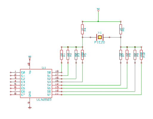
The chip is nothing more than 8 npn darlingtons. I get 4 to make one leg
and other 4 for other leg to make a H bridge.
So the upper two vertical's of H is just 1k resistor the horizontal of H
is pieco and Each of lower part of H is 4 transistors (outputs of ULN)
with different resistors in series. I use 20,40,80,160 ohm to have
chance to change speed of charge. I drive the pieco with 35VDC and
'swing' is same as to use 70V. The piezo is esentila capacitor so using
right resistor in series we can control the speed of bending. And
different resistors in both leegs can do different thing.
Im my 'research' I got best single fire with folowing sequence.
Apply +DC trought largest resistor to piszo make chamber with more volume.
Rest about 15uS.
Apply -DC trought smalest resistor to squeze ink out from chamber
rest about 3-5uS
Energize all transistors to pull both ends of piezo to GND (discharge as
fast as possible) Piezo gone to midle rest position
about 10uS later I deenergize all transistors so both ends of piezo goes
to Vcc (piezo stay in middle)
Wait at least 150uS to ink settle.
With that you can fire 5000 drops per second.
.... but ... again but... I'm have succes to firing isopropil alcohol
only. The watter is unsucesful. I don't know why. Can be surface tension
problem, the water tend to leave some air bubles in chamber and air is
compressible so any air buble is no go. As I have wish to apply solder
resist onto PCB with that and this stuff is like honey I realize that
with that system is not plausible to do it. Maybe if I make two check
valves to make a pump like device ... maybe
and maybe little help how to 'drill' so small holes... I tested two
variant and both works well.
Dril a hole with smalest drill you have. 1mm is good point. (I use brass
material) then pick a piece of thinnest enameled wire (in some relays
the wire is under 0.05mm) and pass it trought hole. Then QUICK fil hole
with solder. You must do that quick to not destroy enamel of wire. Then
in one side (outside) flatten the 'blob' of solder and wire with very
sharp chisel. You can polish that too. After that pull out wire from
opposite side and you got finest hole. If you can't find so thin cooper
wire you can try with glass too. I do sucesfuly under 0.1mm. Break some
glass jar and pick thin scrap of it. Then heat it with torch to red hot
and then with two tweezers quick pull out of fire and stretch. You can
get very fine fiber and use same solder pour method as above. But this
method is little harder as fibre can very easy break when pull it out
from hole. I didn't test it but I think that single carbon fibre out of
some carbon cloth can do the best. Is stronger and can't be burned (as
enamel on cooper). Just don't have piece to check thicknes.
Original message here.
Edited 1 time(s). Last edit at 08/09/2010 04:57AM by casainho.
---
New cutting edge RepRap electronics, ARM 32 bits @ 100MHz runs RepRap @ 725mm/s:
[www.3dprinting-r2c2.com]
|
Re: DIY printhead August 10, 2010 07:14PM |
Registered: 13 years ago Posts: 406 |
Sorry for the delay in replying, been busy doing DIY,
I would prefer that you say/verify that 0.1mm line thickness can be done with this print head :-)
Not as it stands, I have not created a .1mm nozzle, but I see no reason why it would not be possible.
Can you make holes of 0.1mm? Do you think that with a 0.1mm hole we can get a 0.1mm line thickness? we can't get lower thickness lines than the hoke size, right?
I suppose I could if I had to, for our purposes the hole size would define the size of the line close to the head, but the fan angle means that the further from the head the wider the line.
Hmmm, why not try to use/work with the "standart" piezos e can find on electronics components shops? like the ones Arduino users are using? like the ones I got on a local electronics components shops?
They are cheaper and may be easier for others to use, I have had no time this week but I plan to have 3 pairs in a row with some really small silicone tube so that the top two energize therefore pinching the tube, the pair below energize shortly after, the top two release, then the bottom two energize, creating a squeezing action, It may not work but I have to get it out of my system.
|
Re: DIY printhead August 10, 2010 08:07PM |
Registered: 13 years ago Posts: 406 |
Thats interesting stuff from Slavko,
Trace seems a way to wide. For PCB I think 0.2mm is max alowed.. So the
nozzle should be aprox 0.08 as spot is over 2 times larger than orfice
Nozzle needs to be close to paper, the way printers are made, I was just waving the paper about..
The other 'thing' is that I see continous stream. Is it capable to make
only one drop? Ie is it reliable if you apply only one electric impulse
and got spot?
I want to do this, Circuit anyone?, I can build circuits but not design them.
for DOD system the head should use separated drops (pulses) and that
can't be done with PWM. (unles is in MHz range). I make test's and used
As I have wish to apply solder
resist onto PCB......
ULN2804 under microcontroller controll. I put pieco in bridge
configuration to be able to power pieco in both direction..........
Any chance of a circuit?.
.... but ... again but... I'm have succes to firing isopropil alcohol
only. The watter is unsucesful. I don't know why. Can be surface tension
Me to, Water would not work, but adding surfactant seems to work, just a little to break down surface tension, Refill ink works well, but then it should.
As I have wish to apply solder
resist onto PCB with that and this stuff is like honey
I may get some from Rapid electronics and see if it is possible, [www.rapidonline.com]
Dril a hole with smalest drill you have. 1mm is good point. (I use brass
material) then pick a piece of thinnest enameled wire........
I have some tungsten wire from lamp metals, will give it a go.
I tried the head at 5 volts, I get an audible sound from the head but no fluid flows, 20 volts seems the lowest practical value at present.
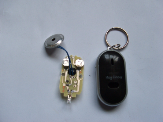
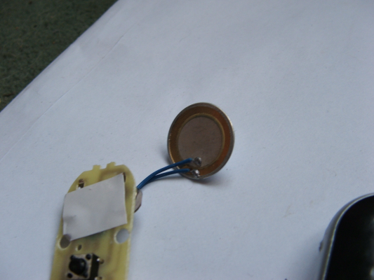
Found some smaller bimorph at poundland, about 18mm diameter, in a keyring that bleeps if you whistle.
|
Re: DIY printhead August 11, 2010 12:20AM |
Registered: 14 years ago Posts: 196 |
I've attached a schematic indicating my best understanding of the circuit as described by Slavko. The difference between a ULN2804 and ULN2803 is really a matter of what interfaces to the device. A ULN2803A would be appropriate for being driven by the outputs of a Arduino (or any other 5v microcontroller). The E0-E7 connections from the ULN2803A would be driven by the outputs from a microcontroller.
|
Re: DIY printhead August 11, 2010 03:22AM |
Registered: 14 years ago Posts: 356 |
johnrpm Wrote:
-------------------------------------------------------
> I tried the head at 5 volts, I get an audible
> sound from the head but no fluid flows, 20 volts
> seems the lowest practical value at present.
If 5 volts would work, it would be very simple :-)
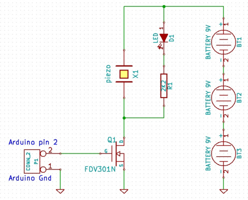
My suggestion is to get 3 x 9V rechargeable batteries, to put in series to get more than 20V. I hope the piezo uses small currents and so that 9V rechargeable batteries will work many hours.
Than I would use an Arduino and a mosfet to switch on-off that high voltage to the piezo.
I was thinking, for the ones who have a RepRap Mendel, we can make use one pin from extruder board, and turn it on when extruder start working and turn it off when extruder stops. We could then wire that pin to an Arduino, which would control the print head! (the same Arduino from which we can start prototyping the print head).
For now I would forget the ULN280x IC, because it's more expensive and makes more difficult to prototype the circuit. And also you have the printed head working without it.
Edited 1 time(s). Last edit at 08/11/2010 03:35AM by casainho.
---
New cutting edge RepRap electronics, ARM 32 bits @ 100MHz runs RepRap @ 725mm/s:
[www.3dprinting-r2c2.com]
|
Re: DIY printhead August 11, 2010 05:27AM |
Registered: 13 years ago Posts: 406 |
|
Re: DIY printhead August 11, 2010 05:44AM |
Registered: 14 years ago Posts: 356 |
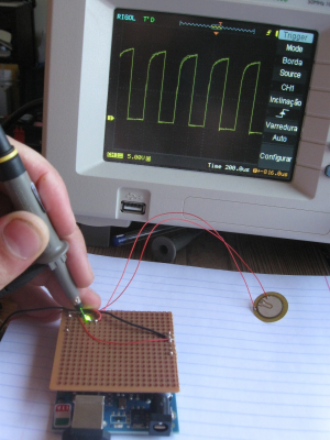
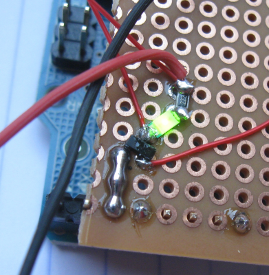
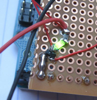
I went and made my piezo buzzing with a signal of 24V, using my regulated power supply and one Arduino. I put a delay of 200us between each turn on/off of the piezo, making a frequency of 2.5KHz.
I used the FDV301N mosfet because I had it in stock. Many others N mosfets should work.
This Arduino can later be connected with 1 wire to RepRap extruder board and get a signal every time extruder gets on/off, and will then turn on/off the needed sequence to enable/disable print jet. The extruder stepper motor wires of RepRap can be disabled while using this print head.
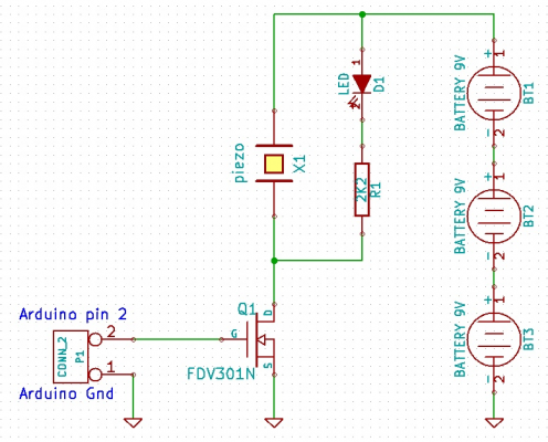
(click on link to see the full image)
Circuit source files for KiCad: circuit_kicad.zip
Source code for Arduino:
John, can you prototype this hardware and test with your print head?
Edited 3 time(s). Last edit at 08/11/2010 05:59AM by casainho.
---
New cutting edge RepRap electronics, ARM 32 bits @ 100MHz runs RepRap @ 725mm/s:
[www.3dprinting-r2c2.com]
I used the FDV301N mosfet because I had it in stock. Many others N mosfets should work.
This Arduino can later be connected with 1 wire to RepRap extruder board and get a signal every time extruder gets on/off, and will then turn on/off the needed sequence to enable/disable print jet. The extruder stepper motor wires of RepRap can be disabled while using this print head.
(click on link to see the full image)
Circuit source files for KiCad: circuit_kicad.zip
Source code for Arduino:
#define PIEZO 2
#define PIEZO_ON digitalWrite(PIEZO, HIGH);
#define PIEZO_OFF digitalWrite(PIEZO, LOW);

void setup()   {
  // initialize the digital pin as an output:
  pinMode(PIEZO, OUTPUT);
}

// the loop() method runs over and over again,
// as long as the Arduino has power

void loop()
{
  PIEZO_ON;
  delayMicroseconds(200);
  PIEZO_OFF;
  delayMicroseconds(200);
}
John, can you prototype this hardware and test with your print head?
Edited 3 time(s). Last edit at 08/11/2010 05:59AM by casainho.
---
New cutting edge RepRap electronics, ARM 32 bits @ 100MHz runs RepRap @ 725mm/s:
[www.3dprinting-r2c2.com]
|
Re: DIY printhead August 11, 2010 05:59AM |
Admin Registered: 17 years ago Posts: 7,879 |
27V supply, 25V FET, OK for an experiment but not likely to be reliable.
[www.hydraraptor.blogspot.com]
[www.hydraraptor.blogspot.com]
|
Re: DIY printhead August 11, 2010 06:04AM |
Registered: 14 years ago Posts: 356 |
nophead Wrote:
-------------------------------------------------------
> 27V supply, 25V FET, OK for an experiment but not
> likely to be reliable.
You mean the voltage limit of FDV301N mosfet? if yes, you are right, but that's the only mosfet I have in stock. Well, I have anothers but expensive ones (more than 1€) for use on my RepRap Mendel Heated Bed.
People should find a better mosfet, even with low on resistance, because FDV301N have about 4ohms which may be a lot for this application.
Edited 2 time(s). Last edit at 08/11/2010 06:08AM by casainho.
---
New cutting edge RepRap electronics, ARM 32 bits @ 100MHz runs RepRap @ 725mm/s:
[www.3dprinting-r2c2.com]
|
Re: DIY printhead August 11, 2010 06:25AM |
Registered: 13 years ago Posts: 406 |
I have a bag full of old HP printheads, the Zcorp gets throught a lot, on the bottom is a foil with the nozzle array, I wonder if I could remove this
and stick it to my head and block the unwanted holes????????,
She who must be obeyed is taking me to Ikea now, more DIY.
edit, I have some signal mosfets in stock that should work.
Edited 1 time(s). Last edit at 08/11/2010 06:29AM by johnrpm.
and stick it to my head and block the unwanted holes????????,
She who must be obeyed is taking me to Ikea now, more DIY.

edit, I have some signal mosfets in stock that should work.
Edited 1 time(s). Last edit at 08/11/2010 06:29AM by johnrpm.
|
Re: DIY printhead August 12, 2010 07:18PM |
Registered: 13 years ago Posts: 406 |
I have built a board that combines both circuits, a simple mosfet (IRF510) suggested by Cashainho, also the H bridge suggested by Slavko and interpreted by Madscifi, thanks again for doing it, I would never have deduced it all, so I can do both, just need to check all connections and programme the arduino, I tried the method for small holes suggested by Slavko, I used tungten wire .002" diameter, spayed a little wax furniture polish on my fingers and coated the wire, drilled a 1mm hole in thin tin plate and soldered it, it worked well, I am leaning towards the thin film approach used by HP, this keeps the nozzle short,I would like to get some brass shim in 6mm discs, this would make a good stick on nozzle.
|
Re: DIY printhead August 13, 2010 04:04AM |
Registered: 14 years ago Posts: 356 |
John, since I have the board with the Arduino + mosfet, if you need something more on that hardware and firmware, you can ask because I will be able to quickly do and test it.
Don't forget to make one print head to me, so I can help you and we can advance more quick.
Do you have a RepRap Mendel? I have one and I would design and print a support for the print head for Mendel. Also I can hack the RepRap firmware and tweak Skeinforge options to let us work with this print head.
---
New cutting edge RepRap electronics, ARM 32 bits @ 100MHz runs RepRap @ 725mm/s:
[www.3dprinting-r2c2.com]
|
Re: DIY printhead August 13, 2010 08:40PM |
Registered: 13 years ago Posts: 406 |
Casainho,
email me your address and I will send you the printhead, I am sick of seeing it at the moment, this morning I put the finishing touches to the board,I had a problem with the mosfet, 5 volts on the gate would not trigger it so after some head scratching changed it for a tip132, then it worked.
I ran the head with the normal drive to ensure all was working well, then connected the head to the new board, no ink would flow, I played around with frequency but no joy, reconnected it to the old drive and could only make it work at high power, I suspected a partial blockage on the nozzle so foolishly tried unblocking it with the syringe, this blew the bimorph of and ink everywhere, the superglue had given way and was allowing air in,
after about an hours cleaning, I decided to make a clamp instead of using superglue, I also closed the nozzle hole down to an impressively small size whilst making the alterations, assembled it all and could not get it to work, to bleed the chamber I use a syringe pressed onto the front face and withdraw the plunger, but not joy, so put the nozzle hole size back to where it was and all worked well, connected it to the new board and still no ink flow.
By this time it was midnight and I had achieved nothing, I think I need to add a bleed screw to get it working with the smallest hole size, with a hole around .1, .2mm the air can escape but smaller than this and its more difficult for the air to get out, I have seen one that has a short tube to retain the air bubble needed, if I can remember how it worked.
I have seen some 20mm bimorphs at rapid electronics, will order some and make a head to suit, it also occurred to me that a car ignition coil may be ok for the lighter spark units, I could add it to the existing drive and switch from transformer to coil.
Could it be that the breakdown spike from the transformer is adding to the voltage on my drive?.
Do you have a RepRap Mendel? I have one and I would design and print a support for the print head for Mendel. Also I can hack the RepRap firmware and tweak Skeinforge options to let us work with this print head.
No but have access to various machines at work.
|
Re: DIY printhead August 13, 2010 10:12PM |
Admin Registered: 17 years ago Posts: 1,791 |
No but have access to various machines at work.
Think you'll do up a WolfStrap or Eiffel?
-Sebastien, RepRap.org library gnome.
Remember, you're all RepRap developers (once you've joined the super-secret developer mailing list), and the wiki, RepRap.org, [reprap.org] is for everyone and everything!
Think you'll do up a WolfStrap or Eiffel?

-Sebastien, RepRap.org library gnome.
Remember, you're all RepRap developers (once you've joined the super-secret developer mailing list), and the wiki, RepRap.org, [reprap.org] is for everyone and everything!

|
Re: DIY printhead August 14, 2010 04:23AM |
Registered: 14 years ago Posts: 356 |
johnrpm Wrote:
-------------------------------------------------------
> Casainho,
> email me your address and I will send you the
> printhead,
Ok I will. But I would like that you get at a relative stable working design and send it to me on that time. We need to have both the same tools.
after some head
> scratching changed it for a tip132, then it
> worked.
Yeah, right. Maybe with even a really cheap transistor it will work!! Like BC856 which costs 0.06€ or less :-)
> Do you have a RepRap Mendel? I have one and I
> would design and print a support for the print
> head for Mendel. Also I can hack the RepRap
> firmware and tweak Skeinforge options to let us
> work with this print head.
>
> No but have access to various machines at work.
Well, I believe the best path is using RepRap Mendel, because we need specific software, firmware and hardware to control the print head. Since RepRap is OpenSource, I think it's much easier and quicker to change it to work with print head. Also we can use it to print the support for print head, to fix it to RepRap. And who knows if some parts of the print head can be printed with RepRap?
John, did you thought in getting a RepRap Mendel?
---
New cutting edge RepRap electronics, ARM 32 bits @ 100MHz runs RepRap @ 725mm/s:
[www.3dprinting-r2c2.com]
|
Re: DIY printhead August 14, 2010 08:07PM |
Registered: 13 years ago Posts: 406 |
I am now sure that the main problem I have been having is the air in the head, today I spent some time getting it to work, the only way was to have it upside down whilst fiddling with the dials, when I touched the head I could only feel a small vibration, but the feed pipe vibrated a lot, this indicates pipe hammer mentioned, I installed a small grubscrew with a point to let the air out but still had to get it going upside down.
I think I remember how it was done on an old rp machine, a miniature screw fitting with a tiny pipe attached to the head, with a small tight fitting rubber pipe pushed onto it, a tiny ball bearing was in the end of the pipe, I suppose the ball bearing was at an ideal distance to achieve the air bubble, simple but effective, I need to get some tiny fittings.
Cashainho, Yes I would prefer to send a head that works well.
I would love to get a mendel but my bank balance would never stand it, My intention was to finish a mechanical television I have been building for to long, then put the finishing touches to my latest cnc machine to clear the decks for the multi material printhead, which will be at least a years work.
P.S still got red hands.
|
Re: DIY printhead August 15, 2010 03:13PM |
Registered: 13 years ago Posts: 406 |
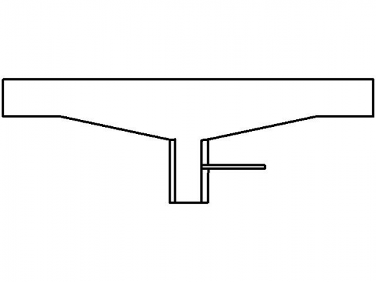
This is a key finder purchased from poundland, when I first saw the cover over the 20mm bimorph I thought it would need removing, but realized that this could form the housing, with a thick walled tube glued with epoxy over the hole, and drilled to take a syringe tube for the fluid feed, then glue a shim nozzle over the front of the tube, it should be possible to do it without a lathe, just a pistol drill, a repraped housing perhaps?.
I have not tried this yet but will when time permits, Apart from this keyring I have not seen bimorphs with this type of housing, but they must be available somewhere?.
Edited 3 time(s). Last edit at 08/15/2010 03:41PM by johnrpm.
I have not tried this yet but will when time permits, Apart from this keyring I have not seen bimorphs with this type of housing, but they must be available somewhere?.
Edited 3 time(s). Last edit at 08/15/2010 03:41PM by johnrpm.
|
Re: DIY printhead August 15, 2010 05:44PM |
Registered: 14 years ago Posts: 196 |
This comment is really a couple of days late, but I thought that it still might be useful for future reference.
The IRF510 is not a good choice for building the drive circuit because the IRF510 is not considered to have a logic level gate and as such it really requires a gate-to-source voltage greater than 4 volts to really turn the device on. A mosfet with a logic level gate, like something from the IRLxxx family, would work much better. Of course, as you discovered, a transistor can work as well.
The IRF510 is not a good choice for building the drive circuit because the IRF510 is not considered to have a logic level gate and as such it really requires a gate-to-source voltage greater than 4 volts to really turn the device on. A mosfet with a logic level gate, like something from the IRLxxx family, would work much better. Of course, as you discovered, a transistor can work as well.
|
Re: DIY printhead August 15, 2010 06:44PM |
Registered: 14 years ago Posts: 356 |
johnrpm Wrote:
-------------------------------------------------------
(...) a repraped housing perhaps?.
Why not start the design in 3D of that part? Are you meaning the print head?
If you design, I can print, test and show in pictures.
In next days I will need to buy components from Farnell - I found there a few piezos and I think I will buy a few units of this one: [uk.farnell.com] -- do you think is a good choice? what about we start discussing for a good piezo for this head? so we can document and others can them buy it and experiment?
---
New cutting edge RepRap electronics, ARM 32 bits @ 100MHz runs RepRap @ 725mm/s:
[www.3dprinting-r2c2.com]
|
Re: DIY printhead August 15, 2010 08:25PM |
Registered: 14 years ago Posts: 196 |
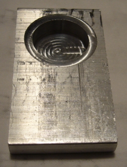
Johnrpm - I've attempted to construct a printhead based on your first design.
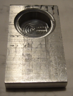
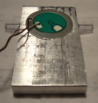
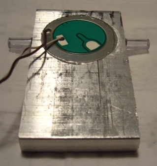
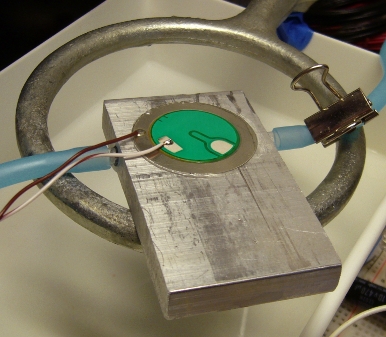
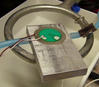
The piezo is from Electronic Goldmine and is about 35mm in diameter. The aluminum is 3/8 inch thick. I milled out a pocket that was 8.4mm deep and drilled a single hole in the center using a #80 drill bit.
Two holes where drilled in opposite sides of the chamber using a #12 drill bit and a small piece of 3/16 thinwall acrylic tubing was epoxied into each hole. The piezo was epoxied in place over the pocket.
Silicone tubing was used to connect one of the acrylic tubes to a liquid reservoir. A bit of tubing was also connected to the other acrylic tube and was used to contain the liquid while the chamber was filled and then it was pinched closed.
The drive circuit is the same combination mosfet and 1k resistor H-bridge that you describe using except that I'm using IRL540N mosfets instead of IRF510 mosfets. A 30 volt power supply was used to power the driver.
I've tried using water and isopropyl alcohol as the liquid.
Observations and Questions
The piezo makes lots of noise at the appropriate times and appears to be driven effectively.
The nozzle leaks very slowly until the liquid level is essentially level with the nozzle. Is an approximately .34mm hole simply too large for the nozzle?
With isopropyl alcohol I'm able to detect changes in the flow of the leak in response to pulsing the piezo. However, the effect is very small and if I lower the external liquid container to the point that there the nozzle does not leak, nothing happens when I pulse the piezo. I've also tried sending a 1 khz signal to the piezo. Again, I'm able to see some effect on leaking liquid, but it is very small. If I raise the external fluid level so that a stream of fluid flows out the nozzle without any assistance, adding the 1khz signal seems to increase the flow slightly.
With water I cannot confirm any visible effect on the leaking fluid.
I think I have all of the air out of the chamber, but I cannot be certain. I might try making a chamber out of acrylic so that I can verify whether or not all of the air has been removed.
I have a different piezo on order. The design of the one that I'm currently using is certainly not ideal.
I need to try a making a smaller nozzle.
Do you have any other suggestions or thoughts?
|
Re: DIY printhead August 16, 2010 04:05AM |
Registered: 13 years ago Posts: 406 |
I also could not get it to work with 30 volts through the tip132, and have gone back to the original drive until I fully understand what is happening, last night I paid more attention to what was happening, the best way to describe it is like a neon lamp, It needs a striking voltage and frequency, and when it is running the voltage can be lowered to 20volts or slightly less, but I do not yet fully understand whether this is to do with priming the fluid or not, maybe someone with fluid dynamics knowledge could help here?.
Since changing the head to a clamp to hold the bimorph instead of superglue I have a lot of trouble getting it to start, maybe a perfect seal is not good???, but when it does start I can rapidly stop and start it and turn the voltage right down, although the frequency has to be higher than with superglue?.
It may be that I need to look at some printheads and look inside them, they must have solved this problem?.
Madscifi, thats a good looking bimorph, what is the other connection point for?, is it to detect resonance.
I have ordered some from rapid piezo they are 20mm dia and 6KH, may deliver smaller
amounts per pulse.
I prime the head by pressing a syringe over the nozzle and sucking out the air, might be worth a try if you have one.
It may also be worth having it upside down to see what is happening with the jet, have some paper in front or you will have red hands and face like me, if its OK I shall nick your idea and put the 20mm disc in an acrylic housing to see whats happening.
Casianho, I will do a model of the enclosed piezo, although I do not yet know where to buy them.
Whilst looking for the enclosed piezo's I saw this scanner
The Reprap could do this, with a thin point and a piezo set up as a knock sensor.
Edited 3 time(s). Last edit at 08/16/2010 08:06AM by johnrpm.
|
Re: DIY printhead August 16, 2010 11:32AM |
Registered: 14 years ago Posts: 356 |
johnrpm Wrote:
-------------------------------------------------------
> I have ordered some from rapid piezo they are
> 20mm dia and 6KH, may deliver smaller
> amounts per pulse.
> Casianho, I will do a model of the enclosed piezo,
> although I do not yet know where to buy them.
You (we all) can buy piezos here: [farnell.com] (Americas, Europes, etc).
I think all of us should use only one type of piezo, since it's sizes, frequency, etc should be important for it work or not on our application. On Farnell we can see the datasheet for each piezo. Who understands about the piezos?
---
New cutting edge RepRap electronics, ARM 32 bits @ 100MHz runs RepRap @ 725mm/s:
[www.3dprinting-r2c2.com]
|
Re: DIY printhead August 16, 2010 02:36PM |
Registered: 13 years ago Posts: 406 |
Could I ask the reprap community for your thoughts,
I have been considering the effects of the fluid chamber in front of the bimorph, its size and shape.
Today I was cutting some 40mm square thin walled tube, the cut off saw is old, with a HSS blade running at 60rpm with 20tpi,
cutting fluid had run into the tiny gap between the tube and backjaw, the fluid was shooting up about 50mm due to the vibration from the blade.
Normally I would not give it a thought, but as I am thinking printheads 24/7 it made me wonder.
If the gap had been larger would the fluid have traveled so far,
Is this an indication for the printhead design
Should the distance and therefore fluid in front of the bimorph be kept to a minimum
Should we have two bimorphs back to back
Should the bottom be flat or shaped in some way
I realise that a lot of people are on holiday at this time of year, but your thoughts would be appreciated.
|
Re: DIY printhead August 16, 2010 05:08PM |
Registered: 14 years ago Posts: 356 |
I need to buy components from Farnell in a few hours. Does anyone know what piezos should I buy from this list?
---
New cutting edge RepRap electronics, ARM 32 bits @ 100MHz runs RepRap @ 725mm/s:
[www.3dprinting-r2c2.com]
---
New cutting edge RepRap electronics, ARM 32 bits @ 100MHz runs RepRap @ 725mm/s:
[www.3dprinting-r2c2.com]
|
Re: DIY printhead August 17, 2010 01:52AM |
Registered: 14 years ago Posts: 196 |
So many things to try, which is part of what makes this an interesting problem...
Johnrpm, based on your descriptions I think I need to spend more time trying to get the device to generate a controllable stream before I try getting it to generate single drops. A higher voltage, either directly or via a transformer between the driver and the piezo, sounds like a good next step to try.
Yes, the extra connection on the piezo is there for the purpose you suggest. It is also the reason that I think I need to find a different piezo. The extra connection means the the piezo material is not covering as much of the disk as possible, so the piezo will not flex as much as possible at a given voltage (or so I assume). The piezos that I ordered showed up today and they turned out to be very small, so I'm don't know if they will be useful or not. For all I know at this point smaller might turn out to be better.
I did try running the device with the nozzle facing up. If i get everything set up so that enough water has leaked out through the nozzle such that it stops leaking and leaves a small drop remains sitting on the surface over the nozzle then I can just see some change in the shape of the drop in response to cycling the piezo. I'm not certain at this point if this is due to a pressure change passing through the liquid column or if it is simply due to vibration of the device as a whole.
I think the idea of using two piezos and squeezing the liquid between them is an interesting idea. I also think that the shape of the chamber is going to turn out to be very important.
Casainho, I'm afraid I don't know much of anything about piezos at this point, so I cannot recommend one over the other. If anyone can recommend some good reference material concerning piezos I would be greatly appreciative.
Speaking of reference material I just found a thesis on the web that looks very useful: Structure- and fluid-dynamics in piezo inkjet printheads. I've only look at the very beginning of the document but it appears to have a lot of detailed background information, which is just what I think we need.
|
Re: DIY printhead August 17, 2010 03:14AM |
Registered: 13 years ago Posts: 406 |
So many things to try, which is part of what makes this an interesting problem...
I agree, its an area where few have been before in comparison to some other things.
based on your descriptions I think I need to spend more time trying to get the device to generate a controllable stream before I try getting it to generate single drops. A higher voltage, either directly or via a transformer between the driver and the piezo, sounds like a good next step to try.
Agreed, the H bridge looks like it will give a lot of control further down the line, but we need to walk before we run at this point and understand some fundamentals first, I think your electronic skills are far better than mine, so I would love to see your circuit design, if you are willing to share.
The piezos that I ordered showed up today and they turned out to be very small, so I'm don't know if they will be useful or not. For all I know at this point smaller might turn out to be better.
At the beginning I was thinking in terms of a continuous bead, like the reprap, but it seems that DOD is the preferred solution, so each pulse must deliver a very small quantity of fluid, so a small disc may be best?.
I did try running the device with the nozzle facing up. If i get everything set up so that enough water has leaked out through the nozzle such that it stops leaking and leaves a small drop remains sitting on the surface over the nozzle then I can just see some change in the shape of the drop in response to cycling the piezo. I'm not certain at this point if this is due to a pressure change passing through the liquid column or if it is simply due to vibration of the device as a whole.
I know just what you mean, when things are right, (whatever that is) and it strikes, the jet instantly cleans the front face of the nozzle and the jet flows with some force.
That paper is a good find.
I need to buy components from Farnell in a few hours. Does anyone know what piezos should I buy from this list?
I honestly can not say buy this one or that one at present, I would say that in general the smaller diameter has a higher frequency and therefore smaller displacement, I have been using 25mm diameter so far but am going to try 20mm, I shall get some even smaller later on.
Edited 1 time(s). Last edit at 08/17/2010 03:36AM by johnrpm.
|
Re: DIY printhead August 17, 2010 04:41AM |
Registered: 14 years ago Posts: 356 |
Ok, I will just buy a few different piezes, keep their reference and datasheet for later compare with the results.
That document seems very good! I uploaded it to RepRap wiki: [reprap.org]
---
New cutting edge RepRap electronics, ARM 32 bits @ 100MHz runs RepRap @ 725mm/s:
[www.3dprinting-r2c2.com]
That document seems very good! I uploaded it to RepRap wiki: [reprap.org]
---
New cutting edge RepRap electronics, ARM 32 bits @ 100MHz runs RepRap @ 725mm/s:
[www.3dprinting-r2c2.com]
|
Re: DIY printhead August 17, 2010 04:59AM |
Admin Registered: 16 years ago Posts: 13,884 |
Hi Casainho,
... i've edited the link to the document - you have to insert a space after the documents name or the separator is part of the name and the link won't work ...
Viktor
--------
Aufruf zum Projekt "Müll-freie Meere" - [reprap.org] -- Deutsche Facebook-Gruppe - [www.facebook.com]
Call for the project "garbage-free seas" - [reprap.org]
Sorry, only registered users may post in this forum.
