DIY printhead
Posted by johnrpm
|
Re: DIY printhead October 01, 2010 04:23AM |
Registered: 16 years ago Posts: 123 |
john,
You misunderstand me. The reason that the nylon produced by the nylon rope trick is wet is that it is being drawn up through the upper liquid. But I am not proposing using the nylon rope trick, just the chemistry behind it. Rather than having two layers of liquid (as in the trick) I am advocating tiny drops coming into contact and forming the nylon, so there is then no upper layer to wet the nylon.
David
|
Re: DIY printhead October 01, 2010 06:49AM |
Registered: 13 years ago Posts: 406 |
Madscifi, you are doing a fantastic job, thanks for shareing your work, it looks like the parameters are tight for a particular
setup but once established should be consistant, do you think?, I don't want to stick my nose into your plan, but it would be interesting to see if the drop forms in the same manner with the polarity reversed.
David, I think I understand what you want to do, but am making suggestions as things pop into my head,
it may just give someone a seed of an idea, who knows?.
Edited 1 time(s). Last edit at 10/01/2010 04:32PM by johnrpm.
Random Precision
|
Re: DIY printhead October 01, 2010 03:10PM |
Registered: 14 years ago Posts: 356 |
madscifi Wrote:
-------------------------------------------------------
> Dalek producing single drops of water, pointing
> down (the animation is a fairly accurate record of
> the orientation), 31 volt, 500 us pulses.
Great work on recording that!!! Thanks for sharing and helping us to "see" :-)
---
New cutting edge RepRap electronics, ARM 32 bits @ 100MHz runs RepRap @ 725mm/s:
[www.3dprinting-r2c2.com]
|
Re: DIY printhead October 02, 2010 12:04AM |
Registered: 14 years ago Posts: 196 |
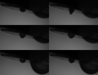
I ran a test where I got everything working correctly (it still takes a couple of minutes to get everything working, air purged, water to the correct level) and then swapped the wires to the piezo without changing anything else. Essentially the device becomes pretty random - occasionally squirting drops, often drizzling large amounts of water, usually producing just little "bumps" that never separate. Sequence is below. I appologize for the missed focus, but it gets the point across, i think.
It is possible to get it to work with the with the wires swapped, but it seems that drizzle becomes a more difficult problem, and when you have enough voltage to produce drops you tend to get more than one, or at least a larger one.
I swapped the wires back and it works correctly again.
I have made the following determination: In order to get the piezo on the device you sent me to push the center of the brass disk into the chamber in response to a positive pulse, the red wire must be negative and the black wire must be positive.
This was determined using the following test. Set the program generating the pulses to generate a 20 ms pulse, repeating every 50 ms. Use the led "strobe" and have it scan from 0 to 40 ms. When everything is working it is easy to see that when wired red to positive that the end of the positive pulse ejects a drop of water and when wired red to negative the beginning of the positive pulse generates a drop of water. I'd like to think that all of the piezos will be wired the same, but since this is not documented in any spec sheets that I have found, I would not assume that to be the case.
I hope that once everything has been set up and the correct settings determined that it will be fairly stable, but some fine tuning may be required in any case. At this point I just don't know.
Edited 1 time(s). Last edit at 10/02/2010 12:11AM by madscifi.
|
Re: DIY printhead October 02, 2010 07:16PM |
Registered: 13 years ago Posts: 406 |
I have made the following determination: In order to get the piezo on the device you sent me to push the center of the brass disk into the chamber in response to a positive pulse, the red wire must be negative and the black wire must be positive.
I agree that it makes sense that the drop is ejected when the disc centre moves towards the nozzle, one way to check this could be to stick some shiny stuff onto the disc and have a laser pointer positioned such that it reflects onto the ceiling or wall, and see which way the spot moves when a pulse is sent.
I am not suggesting you do this, you have put in a lot of time already.
On the first Gif, (how did you do that) are we seeing disc bounce?, as it forms a drop and sucks it back then ejects it?.
Random Precision
|
Re: DIY printhead October 03, 2010 01:02AM |
Registered: 14 years ago Posts: 196 |
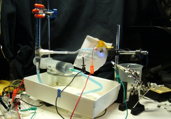
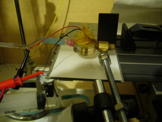
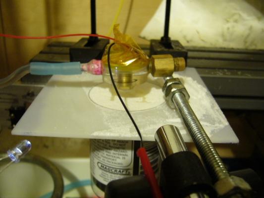
Here is a photo of the current test setup. Did I mention that I'm mechanically inept?
The useful part of the setup to mention are:
1) The bit of white plastic that is epoxied to the pipette and the short whitish tube are parts from a hand cleaner dispenser. They make a rotatable joint that is water tight, which is very useful when trying to flush the air out of the head.
2) The bit of acrylic tubing just to the right of of the hand cleaner components allows the nozzle to be higher than the top of the tubing epoxied to the pipette, which is very useful for keeping air out of the print head and allows lower water pressures at the nozzle without using a manometer configuration (which I've played with but it just adds a level of complexity that is not needed at this point).
3) A syringe connected via tubing to the bottom of the pipette. This allows the water level to be adjusted as necessary without otherwise changing the configuration. Actually, if any air is pushed into the column via the syringe, it tends to flow straight up the pipette and escape into the atmosphere.
4) The top of the pipette is open (not in the picture).
5) Bit of paper behind the nozzle onto which the led "strobe" shines. Back lighting the drops seems to work best for observing directly or taking pictures.
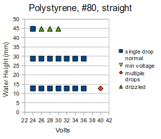
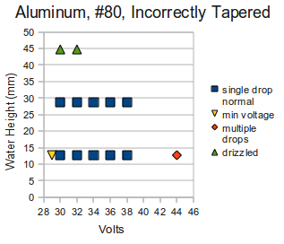
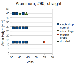
I've run a first set of tests using the nozzles that were constructed last week. The test procedure was:
1) Put nozzle to test on and flush air out.
2) Set water column height to 20 on the pipette (This works out to a height from nozzle of about 13 mm).
3) Set voltage to 30 volts.
4) Verify device is operational (generating drops).
5) Lower voltage until it stops generating drops.
6) Raise voltage until it starts generating drops. This is recorded as min voltage required to generate drops.
7) Set starting voltage.
8) Turn power supply off, wait a couple of seconds, and then turn it on again (often this causes drizzle to whereas just increasing the water level while pulses are being generated might not).
9) Record behavior.
10) If water level == 16 ( ~45 mm above nozzle), next step. Otherwise increase water level 2 readings (16 mm) on pipette and goto step 8.
11) Tired of increasing voltage? If yes, next step. Otherwise, set water height to 20 and increase voltage by 2 volts and goto step 8.
12) If not already generating multiple drops, set water height to 20 and increase voltage until multiple drops are observed. Record voltage.
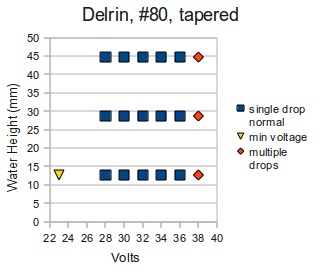
The data should be taken with a grain of your favorite chloride. The height above nozzle is only approximate, although the relative differences are accurate. The tests were done with a single instance of each type of nozzle, and the sequence was only run once. Etc. Water height is height of water column above the nozzle.
Tapered hole (#80 drill, 60 degree etching bit) through a 1.58 mm thick sheet of delrin.
Straight wall hole drilled (#80 drill bit) through a 0.27 mm sheet of polystyrene.
Tapered hole (#80 drill, manually tapered with 60 degree etching bit) through .016 inch aluminum. Mounted the wrong way around.
Straight hole (#80 drill) through .016 inch aluminum
As you can see I neglected to capture a couple of readings. There is some important information missing, like the size and speed of the drops, but this was done by eye and to meaningfully add that information I'll need to photography each test so the drop size and speed can be measured (or at least estimated).
The straight wall hole drilled through aluminum required by a significant amount the highest voltage. The tapered delrin worked over the largest range of water column heights. Although I don't have hard data to back up the claim, it seemed to me that the delrin nozzle worked the "best", in that it had a smaller drop size over a larger range of voltages. The polystyrene nozzle worked amazingly well over a large voltage range.
Anyway, more detailed testing is needed, but I wanted to get some initial indications sooner rather than later.
|
Re: DIY printhead October 03, 2010 01:09AM |
Registered: 14 years ago Posts: 196 |
Johnrpm,
I would be happy to try using a laser to measure the piezo movement, but I did not think that any method I could reasonably expect to construct would work. Your idea has promise, however...
The gif was generated from Gimp. If you save a file as a gif in Gimp and the file has layers, Gimp asks whether you want the layers collapsed as a single image or saved as an animation. So, just open all the images as a set of layers (Open as Layers), crop, and save as a gif.
The behavior might be disk bounce, or it might be due to water rushing in to fill the space and filling a bit more than necessary. I don't know how to tell the difference. Actually, I suppose if you fill the nozzle, cut off the input supply, then run a series, you could eliminate water inrush as a possibility. Due to the need to generate a different drop for each frame this would be difficult - this really calls for a high speed camera, not the series of images captured by a strobe approach.
Edited 2 time(s). Last edit at 10/03/2010 01:42AM by madscifi.
|
Re: DIY printhead October 03, 2010 05:53AM |
Registered: 14 years ago Posts: 356 |
It's important to see and understand your setup! Thanks.
You really look like a "madscifi" :-)
---
New cutting edge RepRap electronics, ARM 32 bits @ 100MHz runs RepRap @ 725mm/s:
[www.3dprinting-r2c2.com]
You really look like a "madscifi" :-)
---
New cutting edge RepRap electronics, ARM 32 bits @ 100MHz runs RepRap @ 725mm/s:
[www.3dprinting-r2c2.com]
|
Re: DIY printhead October 03, 2010 06:33AM |
Registered: 13 years ago Posts: 406 |
Did I mention that I'm mechanically inept?
Your setup is a darn sight tidier than mine, and clean, is the Delrin less ridgid than the other materials?, or is it because it offers less friction that makes it better?, also water is one of the most problematic fluids, other fluids may be easier to jet perhaps,
I just want to say a big thank you on behalf of the community for your work, I know how many hours you must have put into all
that you are doing, and that does not take into account the thinking time.
If you need any bodies making to your own design or discs, let me know by PM
Random Precision
|
Re: DIY printhead October 03, 2010 07:23PM |
Registered: 14 years ago Posts: 196 |
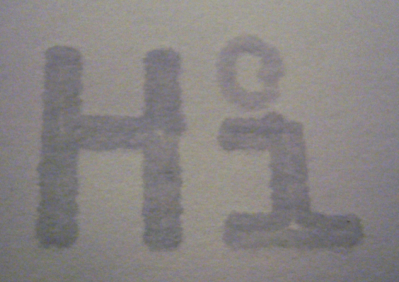
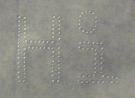
Since I spent yesterday doing the relatively boring and repetitive part of the project, I thought I'd have some fun today.
Image contrast enhanced as it is just plain water on the paper.
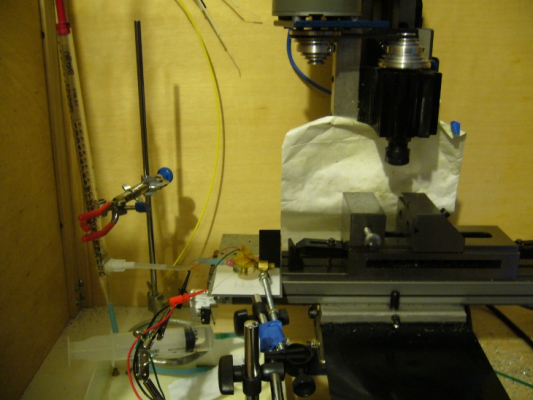
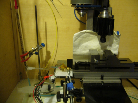
Printing in progress.
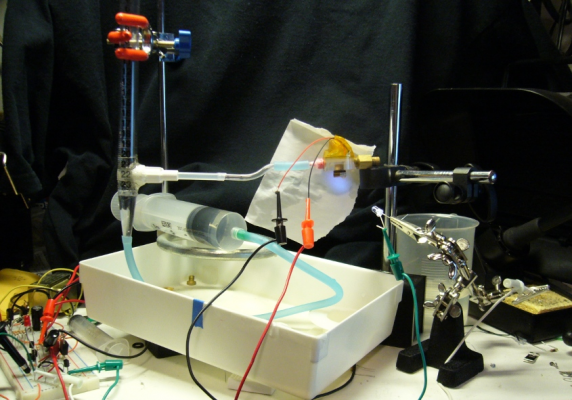
Wider view of setup. Note that the print head does not move, the paper is being moved under the print head.
Sadly, HP and Epson have nothing to worry about.
The Arduino controlling the nozzle was programmed and connected such that every step pulse from EMC2 for the A-axis stepper motor sent a pulse to the piezo instead.
Johnrpm, I'd say your print head works fairly well.
Printed on waxed paper (so the drops would not soak into the paper) and slowed the A-axis rate to one tenth of rate used in the earlier print.
Edited 1 time(s). Last edit at 10/03/2010 09:17PM by madscifi.
|
Re: DIY printhead October 04, 2010 04:57AM |
Registered: 14 years ago Posts: 356 |
HEY! great results!
You are very good at developing and doing reports for community, which is very important! You are good at using different tools to record images and "joining" them with Gimp, using EMC2, etc! I am impressed and is a pleasure o follow such thread on this forum -- I want to learn with the good guys ;-)
---
New cutting edge RepRap electronics, ARM 32 bits @ 100MHz runs RepRap @ 725mm/s:
[www.3dprinting-r2c2.com]
|
Re: DIY printhead October 06, 2010 07:44PM |
Registered: 13 years ago Posts: 7,616 |
|
Re: DIY printhead October 07, 2010 01:41AM |
Registered: 14 years ago Posts: 196 |
Johnrpm, any thank yous belong to you, as it was your idea, design, and construction. I'm tweaking some things around the edges. Thank you for sending me a copy so that I can experiment with it.
I don't actually know that the Delrin nozzle is any better than the others (except that it works over a wider range of water column heights). Mostly I'm probably just wanting it to be since I've made something of a crusade for tapered nozzles. I really should have waited to see if the "it seems to me" is supported after doing some more experiments.
Viktor has kindly sent me various nozzles to test out (thank you), so I need to return to doing the relatively boring and repetitive work of running them through some tests. However, I have one more pointless but fun experiment to finish before I do.
|
Re: DIY printhead October 07, 2010 11:31AM |
Registered: 14 years ago Posts: 196 |
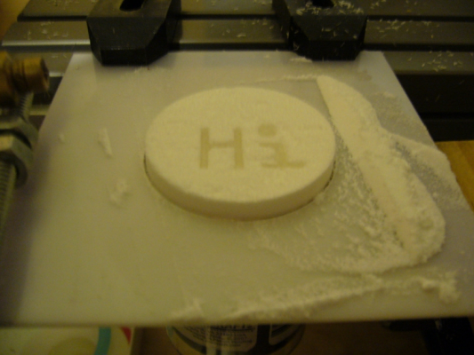
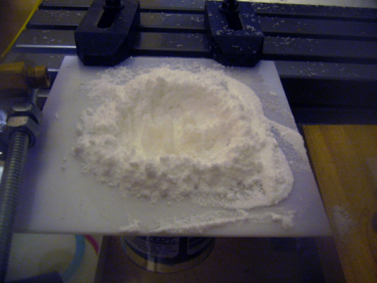
I've cobbled together a very tiny manual powder bed using a fortuitous cylindrical magnet container, a small manual translation stage, some plastic sheeting and scrap of wood. Oh, and lots of hot glue.
The powder consisted of baker's sugar and powered sugar, based on this recipe from the Open3dp website.
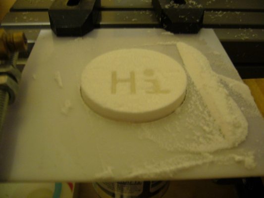
The "Hi" pattern used earlier was printed, the stage moved down one turn, sugar distributed, don't rinse but do repeat 7 to 10 times (I forgot to count).
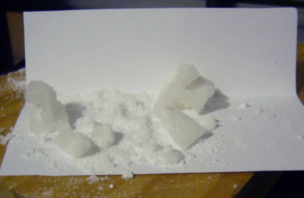
The "H" (parts on the right side) was dropped, so it was damaged. The body of the "i" (on the left, with the base of the body on the paper) survived reasonably well, all things considered. There was a large blob of material on the bottom of each letter that did not want to be brushed off. Too much liquid, I think, so smaller drops are needed.
|
Re: DIY printhead October 07, 2010 04:50PM |
Registered: 13 years ago Posts: 406 |
|
Re: DIY printhead October 08, 2010 02:00AM |
Registered: 14 years ago Posts: 196 |
Certainly not the first within the community to do SLS on a DIY setup, but possibly the first to do it with a DIY (where DIY includes devices made by someone else) drop-on-demand print head.
Now, one question I have: are there any working, small (say 2 to 4 inches on a side), and inexpensive powder beds designs out there? The only design I'm aware of at the moment is Peter Jansen's and it is not really complete (although it looks like a very interesting start).
Now, one question I have: are there any working, small (say 2 to 4 inches on a side), and inexpensive powder beds designs out there? The only design I'm aware of at the moment is Peter Jansen's and it is not really complete (although it looks like a very interesting start).
|
Re: DIY printhead October 08, 2010 03:08AM |
Admin Registered: 16 years ago Posts: 13,884 |
Hi Jim,
try at candyfab ...
Viktor
--------
Aufruf zum Projekt "Müll-freie Meere" - [reprap.org] -- Deutsche Facebook-Gruppe - [www.facebook.com]
Call for the project "garbage-free seas" - [reprap.org]
try at candyfab ...
Viktor
--------
Aufruf zum Projekt "Müll-freie Meere" - [reprap.org] -- Deutsche Facebook-Gruppe - [www.facebook.com]
Call for the project "garbage-free seas" - [reprap.org]
|
Re: DIY printhead October 08, 2010 09:05AM |
Registered: 13 years ago Posts: 406 |
These may help, not sure if they give actual sizes. I built a small SLS some years ago using cylinders and pistons, if you do not need heat then waste pipe 4 inch diameter would do for testing, unless you want to go bigger.
[homemade3dprinter.blogspot.com]
[tech.groups.yahoo.com]
Random Precision
[homemade3dprinter.blogspot.com]
[tech.groups.yahoo.com]
Random Precision
|
Re: DIY printhead October 08, 2010 09:13AM |
Regarding the issue of shrinkage, this is an issue with many materials already in use. People just adjust for it. If there is a support structure which shrinks at the same rate, then the whole block can be cured and dried at the same time to prevent warping.
Just brainstorming a bit more here; if one layer dries or cures before the next layer is applied, may be it will not have an impact since you are depositing droplets that aren't necessarily touching each other. This way they won't draw theselves together as they dry. I suspect that it will be hard to predict exactly what will happen without trying it out. It may be very desirable to dry out a layer at least partially, to avoid having to dry thick layers of the stuff.
Might you just try it out over a larger area using a paint spray head? Spray a layer of A, then a layer of B, and repeat multiple times. You might try using a stencil to control the shape of the product.
If the material has thin enough viscosity, it may be possible to use an off-the-shelf inkjet printer head. One of the commercial gypsum based machines use this approach.
I just had another though regarding ink-jet heads. If you also include a separate head that sprays color ink, then you may also be able to color the finished product. However, it may also interfere with the reaction, so I imagine it would need to be a fairly fine layer of ink.
Joe Dunfee
|
Re: DIY printhead October 08, 2010 05:12PM |
Registered: 13 years ago Posts: 406 |
CNC print
I was not sure where to post this but as its to do with printheads here is a good place.
I have been working on a way to use a cnc machine to print with multiple nozzles, at present, and for some time a single nozzle printhead is probably the main focus, but in time we may be able to develop a multi nozzle head, and as my code skills are on a par with a six year old ( in fact not as good) I have come up with a crude plan.
1 Slice STL file to an image stack
2 write software to process the images, extracting the pixel values and writing a gcode file
3 machine controller to send serial instructions
4 arduino to energise nozzles
No1 , free software already exists for this
No2 , I have not done this yet, but have done similar in the past so should be doable
No3, I have hacked some code to create a macro for Mach3 which sends the information through serial to the arduino, in the form of 2 = pin high and 1 = pin low, so to fire 8 pins would be
22222222, or alternate pins, 21212121, I intended to have zeros and ones but mach3 ignores leading zero's
No,4 I have again hacked a serial library so that the arduino outputs to the pins, I have tested it with eight pins having LED's connected, but see no reason why it would not work with 32 for the mega, although I have not tried it with 32.
Why mach3 and not emc2 ?, I bought mach3 some years ago, emc was not so good then, and as I hate spending money, (makes me feel ill) I intend getting my moneys worth from mach3, emc2 looks very good and I will probably go over to it at some point, but at present I have no idea how to use it let alone do the macro thing.
The gcode looks something like this
g0x0y0z1 (position move)
M1000 Q21212121 (fire pins, M1000 calls the macro and Q is param2() )
g0x1 (position move)
M1000Q 21121221 (fire pins)
g0x2 (position move)
etc
etc
etc
etc
If anyone is interested in this somewhat crude method , I will clean up the code and post it
Random Precision
|
Re: DIY printhead October 09, 2010 01:19AM |
Registered: 14 years ago Posts: 196 |
Viktor and Johnrpm, thanks for the links. Waste pipe sounds promising - I was thinking of acrylic tubing until I remembered the prices on larger sized tubes. Anyway, I'll take a look at the links and see what I can find. What I'm hoping to end up with is something designed to be reproducible, much like the Reprap or Makerbot's design, but not self-replicating. A small powder bed platform would be usable by the various people pursuing laser and commercial inkjet based powder printers. In the case of a single nozzle drop generator, a large print bed is rather pointless.
Joe, that leads directly to the idea of including a dye in the liquid being used as a solvent/binder, which probably would not interfere (depending on the dye and the materials, of course).
Johnrpm, I would be interested in porting the code to EMC2 since that is what I currently run and I don't want to spend the money to buy Mach3 ;-) Writing macros for EMC2 looks to be really easy, although a separate fairly small program might be required to act as a service for the macros. There is also a preexisting interface that pulls an arduino interface into EMC2's HAL, which would have some benefits, but would require modifications as it support only 6 digitial outputs out of the box.
EMC2 only allows user written macros in the M100 -> M199 range (without changing the guts of EMC2). If, as I seem to recall reading, Mach3 does not allow user macros in this range then the gcode generator would have to support EMC2 and Mach3 as separate configuration options.
And now, for the technical question: Do you know if Mach3 includes macros in the motion computations such that a macro is invoked while in motion, or does all motion stop before a macro is executed? EMC2 stops all motion and then executes the macro, waiting to continue the gcode execution until the macro finishes processing. In one way this is good as you know where the drop is going to actually hit on whatever surface it is being dropped on. In another way it is bad because it means that the motion is going to be really slow - move a short distance, stop, eject a drop, move again, etc.
EMC2 also supports a small number of digital out lines via M62 and M63 that are included within the motion planning. That is, in the course of motion planning multiple move commands are blended and the digital output change is queued by the system so it happens at the correct point in the blended motion. This would allow drops to be generated while motion is in progress. This, of course, makes it more complicated to put drops where you want them since the motion and drop travel time would have to be taken into account (in theory, I don't know if it would be necessary from a practical standpoint). I think EMC2's ability to blend moves is limited in how far it can look ahead when blending moves, which limits the ability to provide high speed over a large number of small moves, so this might not actually be useful in the end. I have no idea if Mach3 supports a similar concept or not.
I tried another sugar print this evening (10 layers) and even though I turned the voltage on the piezo down so that I was generating visibly smaller drops, I ended up with one very large chuck of material. I think the problem is that I used a much larger percentage of powered sugar this time.
|
Re: DIY printhead October 09, 2010 03:58PM |
Admin Registered: 16 years ago Posts: 13,884 |
Hi Jim,
... with shugar you'll receive problems because you're wetting much bigger volumes than your droplet-size is
You need something whats drying instantly or cooling down while solving the wetted surface - maybe ABS-dust and Acetone will be a good combination? ... but then you have to vent the building area!
What's possible too, is hot wax with some sort of ceramic dust ... should be even better in relation of viscosity and wetting, than water ...
Viktor
--------
Aufruf zum Projekt "Müll-freie Meere" - [reprap.org] -- Deutsche Facebook-Gruppe - [www.facebook.com]
Call for the project "garbage-free seas" - [reprap.org]
... with shugar you'll receive problems because you're wetting much bigger volumes than your droplet-size is

You need something whats drying instantly or cooling down while solving the wetted surface - maybe ABS-dust and Acetone will be a good combination? ... but then you have to vent the building area!
What's possible too, is hot wax with some sort of ceramic dust ... should be even better in relation of viscosity and wetting, than water ...
Viktor
--------
Aufruf zum Projekt "Müll-freie Meere" - [reprap.org] -- Deutsche Facebook-Gruppe - [www.facebook.com]
Call for the project "garbage-free seas" - [reprap.org]
|
Re: DIY printhead October 09, 2010 04:06PM |
Registered: 13 years ago Posts: 406 |
For the powder bed, I have seen 3 methods that work on commercial machines,
1. the most common is the part bin and feed bin with a roller recoater
2. part bin and roller with hopper recoater
3. part bin and rotary hopper with roller or blade recoater (like a record player with the sylus arm as the recoater)
they all work, 2 has the advantage of smaller footprint but needs the hopper topping up, and 3 has the advantage of simplicity.
And now, for the technical question: Do you know if Mach3 includes macros in the motion computations such that a macro is invoked while in motion, or does all motion stop before a macro is executed?
I think I am right in saying that the default is, that the macro is invoked while in motion, but to make it wait a while loop can be added, (while ismoving wend) makes it wait for, in this case motion to finish before continuing.
In another way it is bad because it means that the motion is going to be really slow - move a short distance, stop, eject a drop, move again, etc.
It may not be to bad if we are only moving short distances ramping will not activate perhaps,
I think EMC2's ability to blend moves is limited in how far it can look ahead when blending moves, which limits the ability to provide high speed over a large number of small moves, so this might not actually be useful in the end. I have no idea if Mach3 supports a similar concept or not.
Mach3 does have look ahead, I think it can be turned of.
Here is the origonal serial library
and the hacked version attached
Edit, added the mach3 macro, its hacked from and existing macro from goodness knows where.
Edited 1 time(s). Last edit at 10/15/2010 07:05AM by johnrpm.
Random Precision
|
Re: DIY printhead October 10, 2010 01:01AM |
Registered: 14 years ago Posts: 196 |
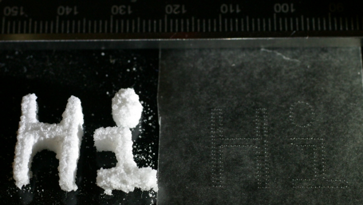
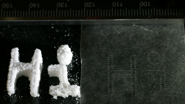
Some more sugar printing.
This is from the same gcode as in the earlier post, with the a-axis scaled so the drop rate was even lower than the earlier post. The powder was 3 parts bakers sugar and 1 part 10x powdered sugar. The layer height was 0.5 mm and there are 10 layers. The pulses were 500 us and 22.7 volts.
In the right portion of the image is the same gcode printed on wax paper so the drop density can be determined. It is just about 1.3 drops per mm.
If the print head is left undisturbed for a day it usually starts right back up the next day without needing any adjustments. Leaving the print in the bed to dry for several hours works much better than 30 minutes, unless one like broken prints.
Since I've lowered the percentage of powdered sugar and dropped the drop density, I don't know which of the two is most significant, although I suspect that they are both important in the case.
Edited 1 time(s). Last edit at 10/10/2010 01:02AM by madscifi.
|
Re: DIY printhead October 27, 2010 03:18AM |
Registered: 14 years ago Posts: 196 |
A variety of real life requirements have made it impossible to spend any time on the print head over the last couple of weeks (and the next several as well). However, I was able to spend most of today working on testing one of the POM nozzles that Viktor made up. Or, at least, that was the plan.
The reality was that after several weeks in the garage and several of the joints in the fluid feed structure leaked. So most of the day was spend applying epoxy and super glue in the appropriate places, letting things dry, identifying more leaks, etc. Eventually everything was once again working reasonably with the nozzle used to make the sugar prints.
The best looking of the nozzles was identified and cut out of the POM strip. It was super-glued to the last unused brass carrier (a hex bolt with a 3mm hole drilled lengthwise through the bolt). This was all done several weeks ago.
I spent about 45 minutes of trying to get the nozzle to eject drops. It would drizzle, but it simply would not eject drops. So I manually pushed the tip of the 0.18mm drill bit that came along with the nozzles through the opening. At this point the nozzle started working. However, it required a minimum of something around 45 volts in order to eject drops. The precise value was impossible to determine as the behavior of the nozzle was very inconsistent. Eventually it stopped working again, so I applied the tip of the drill bit again.
At this point the nozzle appears to be behaving consistently. It requires a minimum voltage of around 23 volts to eject drops, and works reliably at around 25 volts. It appears to work over a range of water heights and voltages that is similar to the delrin nozzle. In theory it ejects drops nearly half the diameter of the drops from the delrin nozzle, but I have not attempted to verify the drop size yet.
It is possible that I've significantly enlarged the opening in the POM with the drill bit as the POM is really soft. It is also possible that I simply dislodged a bit of dust, or pushed back a bit of POM, as it tends not to cut cleanly. It is also possible that the higher voltage was simply a symptom of an air bubble trapped in the nozzle where it was not visible. There are a lot of possibilities here. Although I won't have time in the near future to do any significant additional testing, I will be trying to turn it one at least once a day to see if it remains relatively stable.
Viktor, Mark at Open3dp has suggested kitty litter (pure kaolin clay) as something that tends not to "bleed". I'll give that a try when I get back to trying more printing (although I'll probably get a bag of kaolin clay powder and avoid the kitty litter). Acetone would melt the current head, and wax would be very difficult in the current print head. Both would work better in a tubular style design.
|
Re: DIY printhead October 27, 2010 03:29AM |
Admin Registered: 16 years ago Posts: 13,884 |
Hi Jim,
an interesting fluid is waterglass (sodium silicate) - it dries on open air and solidifies to a relative strong but brittle transparent material and can be heated until some hundred centigrades. The brittleness/elasticity can be handled with additives, but i use it mostly as paste, so haven't any suggestion for the fluid phase.
Another point - POM and Delrin is the same, Delrin is only a branding name ...
Viktor
--------
Aufruf zum Projekt "Müll-freie Meere" - [reprap.org] -- Deutsche Facebook-Gruppe - [www.facebook.com]
Call for the project "garbage-free seas" - [reprap.org]
|
Re: DIY printhead October 27, 2010 07:10AM |
Registered: 13 years ago Posts: 406 |
Maybe stating the obvious, but the fluid needs to have a certain wetability, and the powder needs not to bleed to much,
pure water has surface tension which inhibits wetting, adding surfactant would help or try vodka (Hic),
Gypsum or polyfiller may be worth a try, flour, cement.... Zcorp add various things to optomise powders
thread
Random Precision
pure water has surface tension which inhibits wetting, adding surfactant would help or try vodka (Hic),
Gypsum or polyfiller may be worth a try, flour, cement.... Zcorp add various things to optomise powders
thread
Random Precision
|
Re: DIY printhead November 29, 2010 10:37PM |
John,
I am very interested in the DIY printhead. Please let me know what are the problem ( application, production and design ) of the printhead.
I would like to have following inforrmation
1. What is the frequency
2. What is the displacement of the PZT array
3. What is the size of the orifice
4. Can it use solvent ( MEK ) base ink ?
My email : herbertwonghk@hotmail.com
|
Re: DIY printhead November 30, 2010 03:49AM |
Registered: 13 years ago Posts: 406 |
Hello Macrotek
To try to answer your questions,
1.. frequency with drop on demand is dependent on velocity of head travel, and for continuous stream can be as high as the bimorph will cope with, say 6khz
2.. displacement of the bimorph is small, (but I have not measured it) if thats what you mean, we have not built a multijet array yet, if you are asking what distance between nozzles.
3.. I have made an orifice .050mm, using tungsten filament wire and solder, it should work with a smaller size but the viscosity of fluid will have an effect I think.
4.. I see no reason why MEK would not work, the body material and method of holding the bimorph must be resistant though.
I am very interested in the DIY printhead. Please let me know what are the problem ( application, production and design ) of the printhead.
As you will see in the thread, Madscifi has done a lot of work in trying to understand the process, but both he and I have had
to work on things to bring home the corn for a while, I intend to get back to it when time permits but if you are willing to
help develop it I will help wherever possible.
P.S I have collected 7 dvd writers, (does not mean I will get 7 working diodes) for the laser bubblejet,
Random Precision
|
Re: DIY printhead December 14, 2010 07:21PM |
Registered: 14 years ago Posts: 356 |
Original message of Adrian Bowyer on RepRap dev mailing list:
I had a bit of a deranged-brainstorm-moment a couple of days ago when I foolishly imagined that it should be possible to make an inkjet head in a RepRap machine with no tricky manufacturing steps.
Rather surprisingly, it turned out not to be deranged or foolish after all. It works :-)
Details are here:
[reprap.org]
---
New cutting edge RepRap electronics, ARM 32 bits @ 100MHz runs RepRap @ 725mm/s:
[www.3dprinting-r2c2.com]
Sorry, only registered users may post in this forum.

