Skeinforge 40 Changes to Dimension - Read this for problems with the new version of Skeinforge!
Posted by NewPerfection
|
Re: Skeinforge 40 Changes to Dimension - Read this for problems with the new version of Skeinforge! March 13, 2011 08:03AM |
Registered: 13 years ago Posts: 1,780 |
|
Re: Skeinforge 40 Changes to Dimension - Read this for problems with the new version of Skeinforge! March 13, 2011 01:15PM |
Registered: 13 years ago Posts: 58 |
Like with the magical dissapearing ABS question... one should consider that it is hard to make stuff dissapear (there are physical laws that state it's impossible).. if you accept that your steps are always the same size... then restarting more than you retract, without leaking some out along the move.. will result in a blob...
I'm with nophead that soft material moves less when being driven by a hob, than hard material.. I find it hard to account for 15% of the volume of the feedstock evaporating out during a print.
I believe restart is of little use to us right now, because for a very long PLA move.. I would like to have some extra restart to account for the leakage... (cleanup is less a concern than the weak spot left over after the restart).. but for short moves.. there is no leakage.. so no need for restart... A better, smarter retract is very much needed IMHO.. (not being a coder)... I belive we really would prefer no retract for the little moves within the sparse fill... and some sliding scale of retract that is proportional to the length of moves outside the parts....
Al...
[araspitfire.blogspot.com]
|
Re: Skeinforge 40 Changes to Dimension - Read this for problems with the new version of Skeinforge! March 16, 2011 10:07AM |
Registered: 13 years ago Posts: 63 |
Hi Al,
That is good info and I am trying to follow you... I just installed SF40 but I have serious doubts that when I launch SF, it actually launches a previous version (I have 3 versions now on my PC).
How do I check the SF version I have open? There is a version number, but very far from 39, 40 etc...
Many thanks
|
Re: Skeinforge 40 Changes to Dimension - Read this for problems with the new version of Skeinforge! March 16, 2011 11:05AM |
Registered: 14 years ago Posts: 3,742 |
The Version is the DATE of the version in the top left hand corner of the main window.
SF40 is Version: 11.02.23 for 23 Feb 2011!
Bob Morrison
Wörth am Rhein, Germany
"Luke, use the source!"
BLOG - PHOTOS - Thingiverse
SF40 is Version: 11.02.23 for 23 Feb 2011!
Bob Morrison
Wörth am Rhein, Germany
"Luke, use the source!"
BLOG - PHOTOS - Thingiverse
|
Re: Skeinforge 40 Changes to Dimension - Read this for problems with the new version of Skeinforge! March 16, 2011 12:35PM |
Registered: 13 years ago Posts: 63 |
OK all, I have measured my extruder filament in and I am nearly at 1to1 with Repsnapper , meaning I extrude "10" (which is the minimum) and circa 10mm of filament goes into the extruder. I had to lower the speed for extrusion to around 60-100 as the previous values of 1000s is too fast.
I tried exporting gcode with SF40 and I obtain as result that not enough filament comes out. I check the gcode and for around 20mm of head travel I have an increase of 1 in E (whether I would expect something higher, right? like 15 or so?).
What skeinforge parameter should I play with now to increase the E numbers in the gcode?
|
Re: Skeinforge 40 Changes to Dimension - Read this for problems with the new version of Skeinforge! March 16, 2011 12:51PM |
Registered: 14 years ago Posts: 3,742 |
Do you have dimension activated?
Bob Morrison
Wörth am Rhein, Germany
"Luke, use the source!"
BLOG - PHOTOS - Thingiverse
Bob Morrison
Wörth am Rhein, Germany
"Luke, use the source!"
BLOG - PHOTOS - Thingiverse
|
Re: Skeinforge 40 Changes to Dimension - Read this for problems with the new version of Skeinforge! March 16, 2011 01:01PM |
Registered: 13 years ago Posts: 63 |
|
Re: Skeinforge 40 Changes to Dimension - Read this for problems with the new version of Skeinforge! March 16, 2011 01:29PM |
Registered: 13 years ago Posts: 482 |
By my calculations and where
feedstock diameter: 3mm
nozzle diameter: 0.5mm
mm_out = head travel = 20mm
volume in = volume out
->
Diameter_in*Pi*mm_in = Diameter_out*pi*mm_out
->
mm_in = Diameter_out*mm_out/Diameter_in
= 0.5*20/3
= 3.33 mm -> so your E should read around 3.33mm
Check your packing ratio (My calculations assume 1 which is for PLA and apparantly 0.85 for ABS)
Also, is this just for your first layer or are you getting the same feed for all your layers? (disregarding any raft feeds)
SPEED tab feed & flow rates should be set the same (I have 30)
On RAFT my Object First Layer Flow Rate Multiplier and Object First Layer Flow Rate Multiplier was 0.4 (don't ask me why) which was causing the first layer to be extruding too little. I set these to 1 and immediately got better results.
Then of course there is the width over thickness value which I am not sure where to find nor what it should be, but aparantly that has an effect as well..
Hope this helps
Edited 1 time(s). Last edit at 03/16/2011 01:30PM by AgeingHippy.
|
Re: Skeinforge 40 Changes to Dimension - Read this for problems with the new version of Skeinforge! March 16, 2011 01:42PM |
Registered: 13 years ago Posts: 1,780 |
OK. I'm sold. I finally changed my firmware to be consistent with SF 040 based on the calculated value for Ardrian's geared extruder.
I found that with feed rate and flow rate equal at 20 mm/s and the measure feed stock diameter of 2.85 mm, the value of filament packing ratio that gave the correct width is 0.86 for ABS. And it came out correctly when I printed a 20 mmx20mmx10mm single-walled square with a layer thickness of 0.3 and 0.4 mm.
#define E0_STEPS_PER_MM   85.365      // NEMA 17 59/11 geared extruder 8mm diameter drive SF 40 defines this based on feedstock
#define E1_STEPS_PER_MM   85.365      // NEMA 17 59/11 geared extruder 8mm diameter drive SF 40 defines this based on feedstock
I found that with feed rate and flow rate equal at 20 mm/s and the measure feed stock diameter of 2.85 mm, the value of filament packing ratio that gave the correct width is 0.86 for ABS. And it came out correctly when I printed a 20 mmx20mmx10mm single-walled square with a layer thickness of 0.3 and 0.4 mm.
|
Re: Skeinforge 40 Changes to Dimension - Read this for problems with the new version of Skeinforge! March 16, 2011 02:33PM |
Registered: 13 years ago Posts: 63 |
Thanks AgeingHippy for your help - it confirms to me the wrong value for E.
Packing ratio was fine (tried both 0.85 and 1 with ABS but had not notice a difference at this stage).
The problem is consistent with all layers, not only the beginning.
Being SF ignorant, I spent a couple of hours changing parameters I thought might help, and I discovered that:
- increasing too much the width over thickness makes the software giving error (up to 3 was fine, 5 and above crashes - and I imagine it's why the software cannot calculate the deposition of a too thick trace).
- the only parameter I could find to help increasing my "Es" is the filament diameter. My measure of the filament was 2.9 but I now have to increase the amount of filament pushed through by telling SF that my filament is 2mm instead of 2.9. There must be another way.
I know it's dirty but for the moment works (which does not mean I got a nice print but at least something came out of the extruder).
If anybody knows "the way" to increase the E numbers without having to "pretend" that the filament is thinner, please tell me.
And now I am really tired and slightly depressed - another entire afternoon with SF40 and a reprap and no printing yet.
|
Re: Skeinforge 40 Changes to Dimension - Read this for problems with the new version of Skeinforge! March 16, 2011 02:57PM |
Registered: 13 years ago Posts: 482 |
Keep at it.
Skeinforge is quite a thing to get to work, but in the end it gets you there.
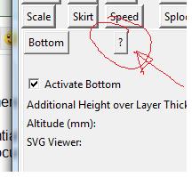
The way I did it was to proceed through all the Craft tabs in a sequential manner. You will see there is a question mark on a button. for each of the tabs. Clicking that brings up a web page of documentation. I essentially set everything to the default to start with.
Edited 1 time(s). Last edit at 03/16/2011 02:57PM by AgeingHippy.
Skeinforge is quite a thing to get to work, but in the end it gets you there.
The way I did it was to proceed through all the Craft tabs in a sequential manner. You will see there is a question mark on a button. for each of the tabs. Clicking that brings up a web page of documentation. I essentially set everything to the default to start with.

Edited 1 time(s). Last edit at 03/16/2011 02:57PM by AgeingHippy.
|
Re: Skeinforge 40 Changes to Dimension - Read this for problems with the new version of Skeinforge! March 16, 2011 03:47PM |
Registered: 13 years ago Posts: 601 |
the help is nice and useful, but out of date and incomplete.
syncra: Have you changed your firmware settings? I'm assuming you did and that is what you meant by "I am nearly at 1to1 with Repsnapper," you haven't mentioned firmware yet, so i'm just making sure.
brnrd: What are your other parameters, like microstepping rate and step angle?
Edited 1 time(s). Last edit at 03/16/2011 03:51PM by Buback.
|
Re: Skeinforge 40 Changes to Dimension - Read this for problems with the new version of Skeinforge! March 16, 2011 06:52PM |
Registered: 13 years ago Posts: 1,780 |
Buback Wrote:
-------------------------------------------------------
>
> brnrd: What are your other parameters, like
> microstepping rate and step angle?
I have techzone Gen 3 remix so I can only to half steps for the moment. So, that's 400 steps per revolution. The microstepping rate I think is determined by SF based on the feed rate etc. But my retract is set to 1.4 mm and restart is set to 0 with a retraction speed of 12 mm/s. I'm still not sure if 1.4 is optimum retract and I haven't tried to see how far I can push the retraction speed yet.
I just built a 4-axis pololu kit that I got from John Yang. But I have too many stuff to print so I can't change it yet. Hopefully, I'll be microstepping by next week.
Edited 1 time(s). Last edit at 03/16/2011 06:58PM by brnrd.
|
Re: Skeinforge 40 Changes to Dimension - Read this for problems with the new version of Skeinforge! March 17, 2011 01:52AM |
Admin Registered: 15 years ago Posts: 1,470 |
Buback Wrote:
-------------------------------------------------------
> the help is nice and useful, but out of date and
> incomplete.
If you access the local help file, which should be buried in your local SkeinForge application folder somewhere, the information is up-to-date. It is still somewhat incomplete though.
|
Help improve the RepRap wiki!
Just click "Edit" in the top-right corner of the page and start typing. Anyone can edit the wiki! |
|
Re: Skeinforge 40 Changes to Dimension - Read this for problems with the new version of Skeinforge! March 17, 2011 05:25AM |
Registered: 13 years ago Posts: 63 |
@ AgeingHappy
Yes I am looking at all SF documentation but I feel like SF was developed when things where completely different and then re-adapted a 1000 times, making the system very complex and documentation does not follow properly... There are really too many parameters when, if you think at the physics, the problem is very simple with few variables! Why are we changing plenty of variables to get the one or two that counts done?
@ Buback
Yes I changed the firmware E/mm (tonokip on RAMPS). My calculation for a modified Wade (same gears of Wade but a brass insert on M6 screw push the filament instead of the hand made M8 threaded bolt typical of Wade - easier to make!) come out with an E/mm = 481. I kept this value slightly lower for iterative adjustments and I think I used 450. Measured the filament going INTO the extruder and it was slightly less than 10mm for a 10 advance in Repsnapper - I believe this was nearly right and left it like that for the moment.
@ Ahmetcemturan
Yes feedrate = flowrate. That's the whole point of SF40, is it? What changes if I increase or decrease both values? I expect the speed of both/extrusion to change, but not the amount of material deposited, right?
Extruder, please see above comment.
Any help or idea is appreciated! Today I printed something but I am still using filament diameter = 2mm in the settings in order to get enough material out, and this should not be it...
|
Re: Skeinforge 40 Changes to Dimension - Read this for problems with the new version of Skeinforge! March 17, 2011 06:18AM |
Registered: 13 years ago Posts: 482 |
Hmm... when you say you feed 10mm and it was almost 10 mm that went in how close is almost?
Perhaps you should try feeding in 100mm and make your adjustments based on that? Then your measurement errors are muchh reduced.
1mm in 10 = 10%
1mm in 100 = 1%
Probably not the root or your problem, but it will bring one of your variables closer to the expected value.
Why not post a small snippet of your gcode here? 3 lines or so each generated with 2mm and 3mm diameter?
|
Re: Skeinforge 40 Changes to Dimension - Read this for problems with the new version of Skeinforge! March 17, 2011 07:33AM |
Registered: 13 years ago Posts: 1,780 |
syncra Wrote:
-------------------------------------------------------
> @ AgeingHappy
>
> Yes I am looking at all SF documentation but I
> feel like SF was developed when things where
> completely different and then re-adapted a 1000
> times, making the system very complex and
> documentation does not follow properly... There
> are really too many parameters when, if you think
> at the physics, the problem is very simple with
> few variables! Why are we changing plenty of
> variables to get the one or two that counts done?
>
> @ Buback
>
> Yes I changed the firmware E/mm (tonokip on
> RAMPS). My calculation for a modified Wade (same
> gears of Wade but a brass insert on M6 screw push
> the filament instead of the hand made M8 threaded
> bolt typical of Wade - easier to make!) come out
> with an E/mm = 481. I kept this value slightly
> lower for iterative adjustments and I think I used
> 450. Measured the filament going INTO the
> extruder and it was slightly less than 10mm for a
> 10 advance in Repsnapper - I believe this was
> nearly right and left it like that for the
> moment.
There are really only two unknown parameters that you'll need to determine in order to set the steps/mm for the feed: the diameter of your filament drive and the filament packing density. You should know your exact gear ratio since it's easy to count the number of teeth. I think people are making a big deal about carefully measuring the actual extruded length which is unecessary. Just measure the diameter of your filament drive carefully with a caliper and error on the larger side. The type used in Adrian's geared extruder is easier to measure than the hobbed type used in Wade's. For a hobbed bolt, I would put a filament against it and see where it makes contact and then measure at the smallest diameter where it makes contact. If it's hobbed right, this should be at the narrowest part. Since the filament packing density can't be larger than 1, you don't want to error on the low side since you won't be able to correct for it in SF 40. Remember that, as pointed out in this topic, this parameter accounts for the fact that your drive is going to dig in to your feed, thereby reducing it's effective diameter.
Then enter your calculated steps/mm in the firmware code using the equation given by nophead above and load it.
Measure your feed diameter carefully with a caliper. Take a few measurements at different spots and average it. Enter this in SF 40. This is very important so that SF can properly calculate how much material to extrude.
Print a single-walled square object (There's one in thingiverse if you can't design one.) with feed and flow rate equal and retraction and restart distance set to 1 and 0 and retract speed to 12 mm/s. I'm not sure if those are the default values. Also start with the default filament packing density for PLA of 0.97 and ABS of 0.85. Then measure the filament width on the top layer on all 4 sides. I usually go with the last side if they're different. Calculate your new filament packing density ratio:
New FPDR = (Old FPDR)*(Desired Filament Width)/(Measured Filament Width)
That should do it. You can test by printing another single-walled object.
You will need to do the print test for each type of feed that you have to set the FPDR and probably if you change the tension on your extruder idler bearing.
You'll then want to adjust your retraction distance to stop ooze. This should be around 1 mm according to Nophead but it may need to be larger to account for gear backlash in the extruder.
>
> @ Ahmetcemturan
>
> Yes feedrate = flowrate. That's the whole point of
> SF40, is it? What changes if I increase or
> decrease both values? I expect the speed of
> both/extrusion to change, but not the amount of
> material deposited, right?
> Extruder, please see above comment.
>
> Any help or idea is appreciated! Today I printed
> something but I am still using filament diameter =
> 2mm in the settings in order to get enough
> material out, and this should not be it...
If you change both feedrate and flowrate together, then the amount of extruded material/extruded length should stay the same.
If you set the filament diameter wrong, then SF40 will not be able to calculate the correct amount to extrude when you change layer thickness.
This is my current understanding. I'm sure someone will correct me if I got anything wrong. That's what's great about this forum.
Edited 2 time(s). Last edit at 03/17/2011 07:41AM by brnrd.
|
Re: Skeinforge 40 Changes to Dimension - Read this for problems with the new version of Skeinforge! March 17, 2011 11:19AM |
Registered: 13 years ago Posts: 601 |
instead of getting repsnapper to extrude 10, measure how much goes into the extruder for each revolution of the large gear. just put a mark or piece of tape on the large gear and move it from 12 o'clock around and back to 12 o'clock
you'll also need a piece of tape on the feedstock. measure the distance at 12 before and after, and the difference is how much went in, which is also your filament gear circumference.
you'll also need a piece of tape on the feedstock. measure the distance at 12 before and after, and the difference is how much went in, which is also your filament gear circumference.
|
Re: Skeinforge 40 Changes to Dimension - Read this for problems with the new version of Skeinforge! March 17, 2011 11:54AM |
Registered: 13 years ago Posts: 1,780 |
Buback Wrote:
-------------------------------------------------------
> instead of getting repsnapper to extrude 10,
> measure how much goes into the extruder for each
> revolution of the large gear. just put a mark or
> piece of tape on the large gear and move it from
> 12 o'clock around and back to 12 o'clock
>
> you'll also need a piece of tape on the feedstock.
> measure the distance at 12 before and after, and
> the difference is how much went in, which is also
> your filament gear circumference.
The problem with this approach is that you have two variables, steps/mm and filament packing density ratio (FPDR), and you only have one measurement, feed displacement per revolution. Since you don't exactly know how much the filament drive is digging into the feed, you might as well just measure your drive diameter and calculate the steps/mm. Perhaps you can use the measured divided by the calculated steps/mm as the first setting for the FPDR. This is what I did and after averaging 3 measurements, I found that the predicted FPDR is lower than what gave me the correct width/thickness: 0.69 vs 0.86. So, in the end, I concluded that I would have saved time if I skipped the step on measuring the actual feed length altogether and tune the FPDR like we used to do with earlier versions tune the flow rate setting.
|
Re: Skeinforge 40 Changes to Dimension - Read this for problems with the new version of Skeinforge! March 17, 2011 12:19PM |
Registered: 13 years ago Posts: 63 |
brnrd Wrote:
- I found that the
> predicted FPDR is lower than what gave me the
> correct width/thickness: 0.69 vs 0.86. So, in the
> end, I concluded that I would have saved time if I
> skipped the step on measuring the actual feed
> length altogether and tune the FPDR like we used
> to do with earlier versions tune the flow rate
> setting.
Looks like this FDPR is the parameter I wanted to play with for increasing/decreasing the material fed! It would make sense... So leave filament diameter at its measured value and play with FDPR...
But what is the real definition of filament packing density ratio? Is it the "compressability" of the material BETWEEN the extruder and the hot end?
I actually found something interesting, like a sort of "micro-waving" in the thickness of a thin wall (this affects the quality of external straight walls as well). My modified Wade feeds a bowden cable of nearly 50cm to the hot end. Is it this spring effect of material in the cable that causes the waves?
Tricky question I know....
|
Re: Skeinforge 40 Changes to Dimension - Read this for problems with the new version of Skeinforge! March 17, 2011 04:25PM |
Registered: 13 years ago Posts: 28 |
syncra Wrote:
-------------------------------------------------------
> I actually found something interesting, like a
> sort of "micro-waving" in the thickness of a thin
> wall (this affects the quality of external
> straight walls as well). My modified Wade feeds a
> bowden cable of nearly 50cm to the hot end. Is it
> this spring effect of material in the cable that
> causes the waves?
>
> Tricky question I know....
I also have a bowden cable of roughly the same length, and in my experience any change in flow rate requires a large corresponding push or pull from your extruder pump. If anything the spring to your cable and feedstock should make the flow more even and unless these waves occur once over the span of tens of millimeters, then I doubt it's your feedstock/pump that's causing it.
Do these waves appear on straight lines that are parallel to your x and y axes? I've seen similar waves on my printer during x moves that were caused by the threaded rod drive my setup uses, while moves along the y axis showed no waving. If you're using a belt driven printer, then check your pulleys & bearings if you can isolate it to a single axis.
The only other possibility I could imagine would be if the tooth marks in your feedstock from your pump (are you using a hobbed/toothed bolt like in a wade's extruder?) are catching on something near your hot end causing the feedstock to move in short surges.
|
Re: Skeinforge 40 Changes to Dimension - Read this for problems with the new version of Skeinforge! March 17, 2011 10:54PM |
Admin Registered: 15 years ago Posts: 1,470 |
syncra Wrote:
-------------------------------------------------------
> Looks like this FDPR is the parameter I wanted to
> play with for increasing/decreasing the material
> fed! It would make sense... So leave filament
> diameter at its measured value and play with
> FDPR...
> But what is the real definition of filament
> packing density ratio? Is it the
> "compressability" of the material BETWEEN the
> extruder and the hot end?
FDPR is the difference in volume between the incoming filament and what comes out of the extruder. In reality, it should be 1.0. There are some theories that ABS changes density slightly when run through the extruder, but I'm not sure that actually happens. I have my FDPR set at 1.0 and get perfect prints. If your e_steps_per_mm is set right, and your filament diameter is set right, you should be getting the exact right extrusion rate.
|
Help improve the RepRap wiki!
Just click "Edit" in the top-right corner of the page and start typing. Anyone can edit the wiki! |
|
Re: Skeinforge 40 Changes to Dimension - Read this for problems with the new version of Skeinforge! March 18, 2011 01:38AM |
Registered: 13 years ago Posts: 601 |
brnrd Wrote:
-------------------------------------------------------
> The problem with this approach is that you have
> two variables, steps/mm and filament packing
> density ratio (FPDR), and you only have one
> measurement, feed displacement per revolution.
> Since you don't exactly know how much the filament
> drive is digging into the feed, you might as well
> just measure your drive diameter and calculate the
> steps/mm. Perhaps you can use the measured divided
> by the calculated steps/mm as the first setting
> for the FPDR. This is what I did and after
> averaging 3 measurements, I found that the
> predicted FPDR is lower than what gave me the
> correct width/thickness: 0.69 vs 0.86. So, in the
> end, I concluded that I would have saved time if I
> skipped the step on measuring the actual feed
> length altogether and tune the FPDR like we used
> to do with earlier versions tune the flow rate
> setting.
Are you measuring with PLA or ABS? i guess it's best to do any measurements with PLA, since it's much closer to 1:1 than ABS. This removes the FPDR from the calculations, as long as your plastic stays the same (but, yes, you will need to alter it to fine tune your width/thickness).
|
Re: Skeinforge 40 Changes to Dimension - Read this for problems with the new version of Skeinforge! March 18, 2011 01:44AM |
Registered: 13 years ago Posts: 1,780 |
NewPerfection Wrote:
-------------------------------------------------------
>
> FDPR is the difference in volume between the
> incoming filament and what comes out of the
> extruder. In reality, it should be 1.0. There
> are some theories that ABS changes density
> slightly when run through the extruder, but I'm
> not sure that actually happens. I have my FDPR
> set at 1.0 and get perfect prints. If your
> e_steps_per_mm is set right, and your filament
> diameter is set right, you should be getting the
> exact right extrusion rate.
I doesn't make sense for the FPDR to be 1. If you look at your feed after going through the filament drive, you will see teeth marks on it. PLA is harder than ABS so the teeth don't dig in as deep. By digging in to the feed, the effective diameter of the filament drive is reduced, which reduces the effective circumference and therefore the steps per mm. Other things may be happening but I think this is probably the most significant effect unless you have a bowden cable between your drive and your hot end. If you keep FPDR at 1, then you will need to change the steps per mm value in your firmware when you change from PLA to ABS and vice versa. This is more hassle than changing the FPDR parameter in SF and I'm sure this is why that paramter is there.
|
Re: Skeinforge 40 Changes to Dimension - Read this for problems with the new version of Skeinforge! March 18, 2011 06:14AM |
Registered: 13 years ago Posts: 482 |
brnrd Wrote:
-------------------------------------------------------
> NewPerfection Wrote:
> --------------------------------------------------
> -----
> I doesn't make sense for the FPDR to be 1. If you
> look at your feed after going through the filament
> drive, you will see teeth marks on it. PLA is
> harder than ABS so the teeth don't dig in as deep.
> By digging in to the feed, the effective diameter
> of the filament drive is reduced, which reduces
> the effective circumference and therefore the
> steps per mm.
If the plastic is being compressed (increasing the density of the plastic) by the teeth rather than displaced then I would guess the melting of the plastic in the hot end would restore the density to the norm, so the compression factor of the teeth would be removed.
|
Re: Skeinforge 40 Changes to Dimension - Read this for problems with the new version of Skeinforge! March 18, 2011 08:56AM |
Registered: 13 years ago Posts: 1,780 |
I think the name that Enrique used to describe this parameter is confusing since the feed is not really changing density. It might have been better to call it Filament Drive Diameter Correction Ratio. His explanation in his blog is quite clear.
If it was just compression and the teeth doesn't dig in to the feed, then the steps per mm wouldn't change between PLA and ABS. Compressing the plastic will not change it's density. It would merely flatten it.
Quote
The tricky setting is the 'Filament Packing Density'. The default is 0.85, this is for ABS.
The default value is so low for ABS because ABS is relatively soft and with a pinch wheel extruder the teeth of the pinch dig in farther, so it sees a smaller effective diameter. With a hard plastic like PLA the teeth of the pinch wheel don't dig in as far, so it sees a larger effective diameter, so feeds faster, so for PLA the value should be around 0.97. This is with Wade's hobbed bolt. The effect is less significant with larger pinch wheels.
Overall, you'll have to find the optimal effective 'Filament Packing Density' by experiment.
If it was just compression and the teeth doesn't dig in to the feed, then the steps per mm wouldn't change between PLA and ABS. Compressing the plastic will not change it's density. It would merely flatten it.
|
Re: Skeinforge 40 Changes to Dimension - Read this for problems with the new version of Skeinforge! March 18, 2011 10:53AM |
Registered: 13 years ago Posts: 482 |
I'm sorry - I don't see the difference.
First let's make a distinction between my use of compression vs displacement.
Compression as I use it is the plastic being squeezed so the same amount of plastic occupies a smaller volume - which must result in the density increasing.
Displacement as I use it means the plastic displaced by the teeth goes elsewhere, possibly widening the feedstock profile slightly.
If the teeth effect is not compression of the plastic then it has to have been displaced in some way. Perhaps making it wider by 0.001mm or moving the plastic into the gaps between the teeth or whatever.
If there is no change in density then the volume of plastic is the same regardless of the shape entering the hot end.
Or am I just being thick? My understanding of entering the filament diameter is to calculate the volume as it enters. 5mm of 3mm feedstock (5*3*pi) is the same as squeezing the same amount of plastic into a different shape whether it is a square or shapless blob or a shape of a mouse. Stick both in a bucket of water and the same volume will be displaced.
|
Re: Skeinforge 40 Changes to Dimension - Read this for problems with the new version of Skeinforge! March 18, 2011 12:32PM |
Admin Registered: 17 years ago Posts: 7,879 |
It is nothing to do with density changes. PLA feeds into the extruder faster for the same pinch wheel diameter, I have measured it. So with pinch wheel feed you can't have one value for E_STEPS_PER_MM in the firmware. If you do then you need to bodge it with FPDR for one plastic or the other. I suspect filament diameter will have some effect on how fast it feeds as well, particularly for PLA.
The only sensible value to send to the firmware is the number of steps to move and have a pinch wheel diameter property per plastic host side.
[www.hydraraptor.blogspot.com]
The only sensible value to send to the firmware is the number of steps to move and have a pinch wheel diameter property per plastic host side.
[www.hydraraptor.blogspot.com]
|
Re: Skeinforge 40 Changes to Dimension - Read this for problems with the new version of Skeinforge! March 18, 2011 12:50PM |
Registered: 13 years ago Posts: 482 |
once again Nophead is succinct and clears any misunderstandings.
I just re-read brnrd's post and see he has decided to call it the Filament Drive Diameter Correction Ratio - so if my feed or steps per mm is based on the PLA, I need to modify the input volume (using the same steps per mm) for any other plastic since the plastic will experiance a different amount of movement due to the hardness/softness of the plastic as compared to the PLA.
So - this can easily be determined by measurement.
If you establish your Esteps per mm for PLA accurately (E100 actually feeds 100mm). Then instruct your extruder to extrude 100mm of your new plastic (say ABS).
Take the actual amount of ABS fed into the extruder and divide by 100 and you have your Filament Drive Diameter Correction Ratio or Filament Packing Density as it is called in Skeinforge.
Simples
Edited 1 time(s). Last edit at 03/18/2011 01:50PM by AgeingHippy.


Sorry, only registered users may post in this forum.