optical end stop
Posted by charlieRC
|
optical end stop April 10, 2018 11:43AM |
Registered: 11 years ago Posts: 157 |
This may not be the place for this question, and if not I apologize.
I was sent Ultimachine optical end stops with one of my Rambo boards even though I didn't need them. I was using mechanical switches.
I thought I would try to see how they worked so that I might include them in other projects. On a Arduino Nano, I connected VCC to 5v, GND to nano GND, and for signal, tried both A0 with analogRead and D11 with both digitalRead and analogRead and I could see no change when I ran a piece of plastic through the optical sensor. Obviously, I have oversimplified how these things work. I tried 3 of the sensors in case one was defective, but no luck. Can someone give me a good way to check these out using an Arduino?
Here’s a link to the device I am trying to use.
[ultimachine.com]
Here's the code I used
Edited 2 time(s). Last edit at 04/10/2018 08:09PM by charlieRC.
I was sent Ultimachine optical end stops with one of my Rambo boards even though I didn't need them. I was using mechanical switches.
I thought I would try to see how they worked so that I might include them in other projects. On a Arduino Nano, I connected VCC to 5v, GND to nano GND, and for signal, tried both A0 with analogRead and D11 with both digitalRead and analogRead and I could see no change when I ran a piece of plastic through the optical sensor. Obviously, I have oversimplified how these things work. I tried 3 of the sensors in case one was defective, but no luck. Can someone give me a good way to check these out using an Arduino?
Here’s a link to the device I am trying to use.
[ultimachine.com]
Here's the code I used
//int aPin = A0;
int dPin = 11;
int v = 0;
void setup() {
  pinMode(dPin,INPUT);
  Serial.begin(9600);
}

void loop() {
//  v = analogRead(aPin);
  v = digitalRead(dPin);
  Serial.println(v);
}
digitalRead only returned 1 and analogRead returns an integer between 190 and 220 randomly regardless of whether the sensor was blocked or not.Edited 2 time(s). Last edit at 04/10/2018 08:09PM by charlieRC.
|
Re: optical end stop April 11, 2018 09:15AM |
Admin Registered: 13 years ago Posts: 7,000 |
|
Re: optical end stop April 11, 2018 09:24AM |
Admin Registered: 13 years ago Posts: 7,000 |
oh and it should be digital
also what are you using as an optical interrupter? a lot of 3d printed things are IR transparent. Use a bit of old fashioned stick or cardboard.
Also It doesn't work in bright light.... or direct sunlight.
Edited 1 time(s). Last edit at 04/11/2018 09:26AM by Dust.
also what are you using as an optical interrupter? a lot of 3d printed things are IR transparent. Use a bit of old fashioned stick or cardboard.
Also It doesn't work in bright light.... or direct sunlight.
Edited 1 time(s). Last edit at 04/11/2018 09:26AM by Dust.
|
Re: optical end stop April 11, 2018 07:53PM |
Registered: 11 years ago Posts: 157 |
It is a 5v nano, and I have seen using anything that would block light...pieces of heave plastic, wood, or think cardboard,.. for testing purposes. I have been trying to talk to tech support at ultimachine, the source of the sensor board, but I am not always that great at describing a problem and I don’t think we are on the same wave length. I think he is telling me that the led indicator should go out and the signal voltage should change when something interrupts the sensor but in fact nothing I do with the sensor has any effect on ether the led or the sensor signal. The signal stays high (5v) on the digital pin 11 (where the signal wire is connected). I have four of these sensors and none have ever been used and all are doing the same thing (which is not doing anything)
|
Re: optical end stop April 11, 2018 11:17PM |
Admin Registered: 13 years ago Posts: 7,000 |
|
Re: optical end stop April 12, 2018 12:03PM |
Registered: 11 years ago Posts: 157 |
Quote
Dust
The tech is correct, the led should change state as well as the output voltage, you shouldn't even need a nano, just power and gnd and something to interrupt the light
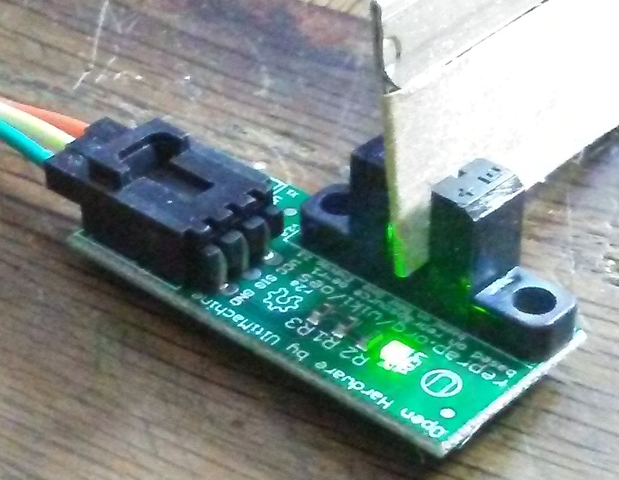
That's the thing. When I put something in the sensor to block the IR, the LED is not changing state and the output voltage is not changing. Am I still not understanding. I would write these off as defective except that I have four of them that behave exactly the same (or maybe mis-behave the same). Please look at the attached image with the sensor "interrupted". Doing this causes no change in the LED or signal. Am I still misunderstanding? I think the tech thinks so.
BTW, thinking that maybe this only reacts momentarily when the sensor is interrupted, I tried to spot some signal change on my oscilloscope and logic analyser and in both cases, nothing but flat line.
Charlie
Edited 1 time(s). Last edit at 04/12/2018 12:08PM by charlieRC.
|
Re: optical end stop April 13, 2018 06:30AM |
Admin Registered: 13 years ago Posts: 7,000 |
looking at the image
You can see the led is on the left and the sensor is on the right.
The internal led in the opto switch should always be on. connected to vcc via R2 and gnd, so check you have a voltage over those two pins and check there is a diode there in diode mode
also its based on [reprap.org]
the -ve on the sensor side is the raw output, take a look at that
But I suspect that someone has applied more than 5v and destroyed the optical switch.
|
Re: optical end stop April 13, 2018 10:57AM |
Registered: 11 years ago Posts: 157 |
I've checked everything as best I can. The empty pcb above filled in the missing information about how everything should be wired. I checked all the traces and the resistence on R1, R2 and R3 and got 2.4k, 220 and 1k respectively which sounds reasonable and everything else looks as it should. It all comes down to the diode and now I am convinced these were all defective when I received them.. I know I didn't damage them because they were in the origiinal package until a couple days ago when I started researching this and the only power ever applied to these pcb's was from the 5v rail of the nano, so that leaves me with only possibility that all four of these were defective when I got them. I know ultimachine is not buying it, so now my problem is a different one. I need to find an alternate source for this stuff since at this point, I don't trust ultimachine. These were only a few bucks each so the trust is much more important to me than the money. I will move on.
Thanks for the help thinking this out.
Charlie
Thanks for the help thinking this out.
Charlie
Sorry, only registered users may post in this forum.