Sanguinololu layout
Posted by sungod3k
|
Sanguinololu layout June 21, 2014 08:58PM |
Registered: 11 years ago Posts: 805 |
Hi,
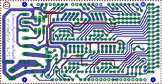
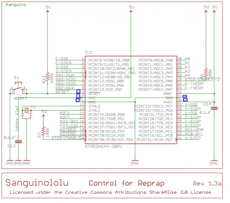
Im trying to find a possible short on my board and while I can test the 5V and 12V from usb/screwterminal to the voltage regulator I have no idea which traces should be connected and which should not.
RAMPS has nice little schematic for that I cant find the same for the Sanguinololu. Or is there maybe an easier way to check that.
Im thankful for every pointer.
|
Re: Sanguinololu layout June 21, 2014 10:03PM |
Registered: 11 years ago Posts: 805 |
Little update:
I checked electronics layout because marlin always reported hardware resets. So I tested continuity from GND to all the pins.
Im getting beeps on pins 11 and 31 which are ground, also on 10 and 30 which are VCC and AVCC (from what I read those have powersupply function)
BUT most interestingly I also get continuity on pin 9 which is reset and that should only be the case if the button is pressed, shouldnt it?
That could explain some of the unresponsive behavior of the board, the reset button has no other connected function and I can just remove it and hope the the board isnt reset permanently anymore, right?
|
Re: Sanguinololu layout June 23, 2014 03:17PM |
Registered: 10 years ago Posts: 92 |
I would think a shorted reset line would definitely cause constant resets.
But before you remove the button, I've got a few questions:
1.) Does your continuity checker have a resistance setting? Check how many ohms you're seeing--if they're low enough the checker will beep even if they aren't directly connected. The fact that you can power it up shows that 10 and 30 can't be shorted to ground.
2.) If it beeps for 10 and 30, it should definitely beep for everything else on the 5V bus. Does it?
3.) You're doing this without the board powered, right? Voltages could screw with the continuity checker's circuits.
4.) If you swap the lines on the continuity checker, does it still beep? It could be responding to some diode.
5.) Check to see if you have a jumper on JP25. That connects a pin from the FTDI chip to nRESET (through a cap, so it still shouldn't register as continuous). If you do, pull it off and see if it still measures the same.
6.) What voltage shows up on that nRESET line when the board is powered? If it's not 0V, that button isn't shorted.
I tried grabbing the Gerber files for the board from github--if you have those, you can look at them with a free gerber viewer like GC-Prevue if you're looking for a picture like you posted above. But I'm not set up for git, and my interest in getting there is minimal.
But can't you just look at the two photos of top and bottom of the board to see where the traces go?
Sorry, only registered users may post in this forum.

