My mods for curing 5V USB/7805 problems on Sanguinololu 1.3a
Posted by enif
|
My mods for curing 5V USB/7805 problems on Sanguinololu 1.3a August 29, 2014 03:42PM |
Registered: 9 years ago Posts: 590 |
I'd just like to document here, how, for my RapRaps, I solved the known issues of the Sanguinololu 1.3a board with respect to the 5V conflict between the USB port and the 7805 regulator, and the possible backfeeding of the USB 5V into the 12V input line. I don't know if others have posted the same ideas before (I searched, but didn't find). So in case I missed something, please be gentle with me - it's my first post here ;-)
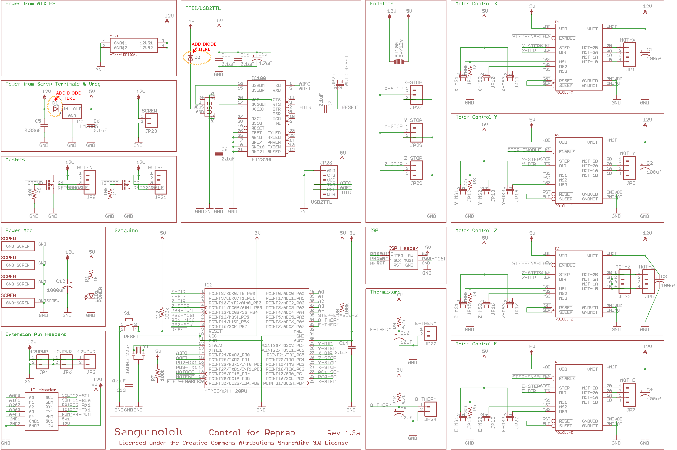
Instead of just cutting a trace or even completely removing the 7805 regulator (which are usually recommended), I simply added two diodes, one into USB Vcc input line, and the other into the 12V input line of the 7805 regulator, as is shown on the attached modified Sanguinololu schematics. These diodes ensure that the current is not flowing in the wrong direction.
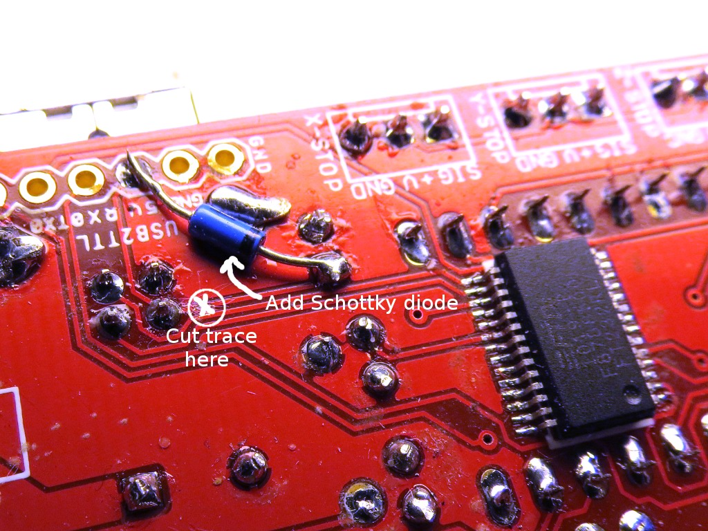
For keeping the voltage drop as low as possible, I use a Schottky diode on the USV Vcc line. I found it easier to solder the anode of the diode onto the 5V pin of (usually unused) USB2TTL connector.
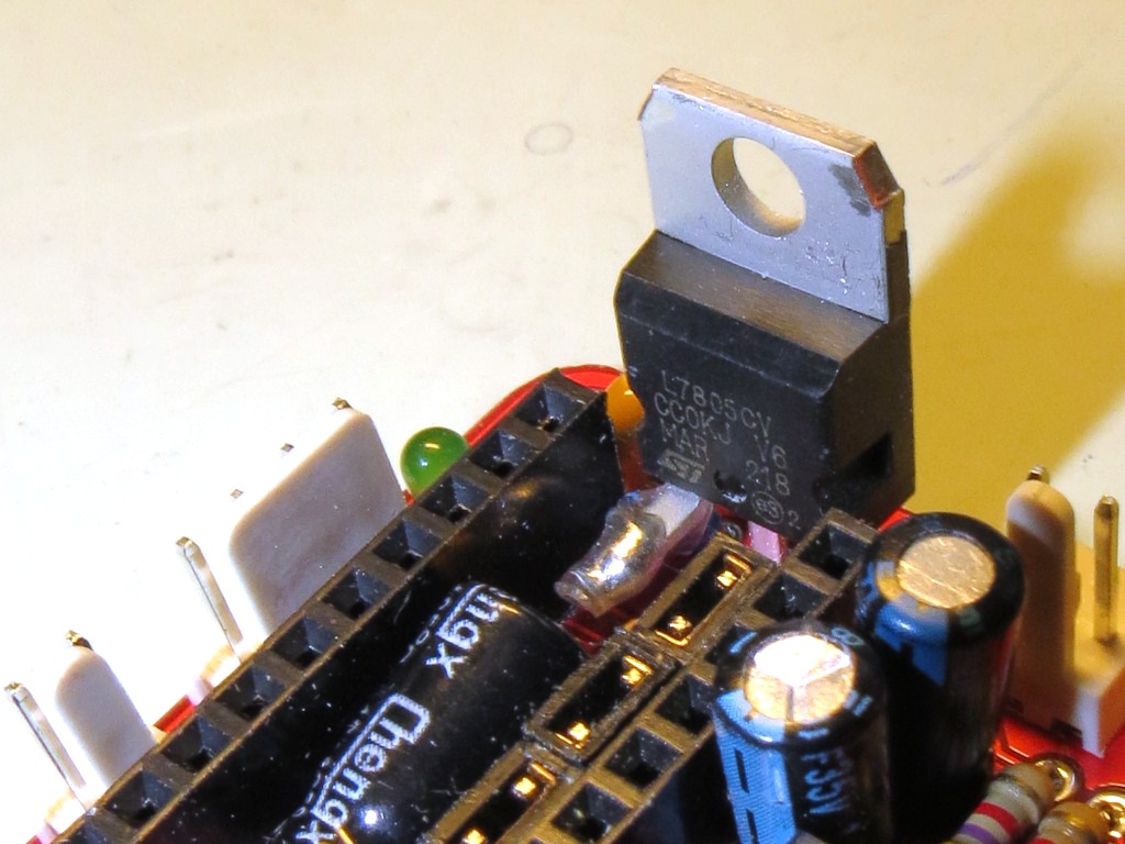
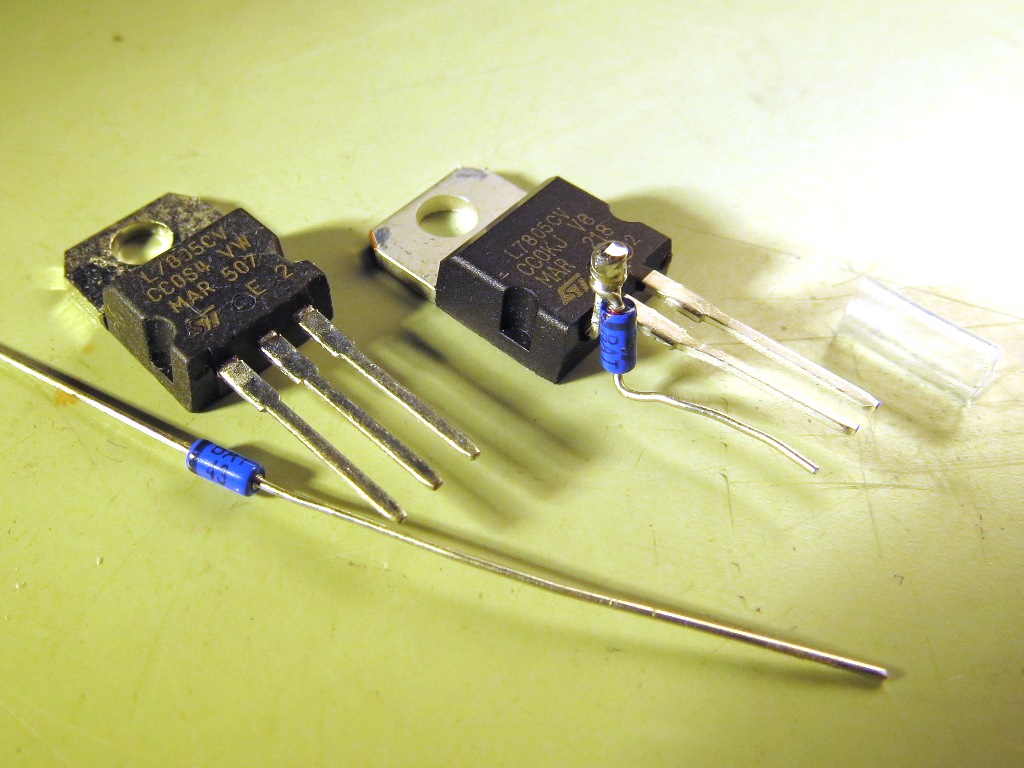
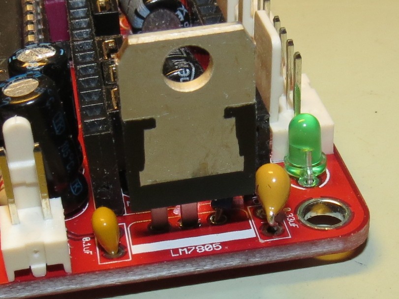
For avoiding the backfeeding of the USB 5V into the 12V input (and through it back into the switched-off power supply), I solder the diode directly to the input leg of the 7805 before soldering it to the PCB, as shown on the attached pictures.
I use BAT43 Schottky diodes that allow forward currents of 200mA. This is just fine as long as you do not connect heavy external 5V loads to the Sanguinololu. For higher currents, you might want to use 1N5819 or similar.
I have used these mods on at least 6 Sanguinulolu boards over the past year, and never again had any power problems, regardless whether I have power just from USB (e.g. to program the ATmega1824), just from 12V supply (when printing from SD-card) or have powered both USB and 12V supply (when printing via US .
.
Instead of just cutting a trace or even completely removing the 7805 regulator (which are usually recommended), I simply added two diodes, one into USB Vcc input line, and the other into the 12V input line of the 7805 regulator, as is shown on the attached modified Sanguinololu schematics. These diodes ensure that the current is not flowing in the wrong direction.
For keeping the voltage drop as low as possible, I use a Schottky diode on the USV Vcc line. I found it easier to solder the anode of the diode onto the 5V pin of (usually unused) USB2TTL connector.
For avoiding the backfeeding of the USB 5V into the 12V input (and through it back into the switched-off power supply), I solder the diode directly to the input leg of the 7805 before soldering it to the PCB, as shown on the attached pictures.
I use BAT43 Schottky diodes that allow forward currents of 200mA. This is just fine as long as you do not connect heavy external 5V loads to the Sanguinololu. For higher currents, you might want to use 1N5819 or similar.
I have used these mods on at least 6 Sanguinulolu boards over the past year, and never again had any power problems, regardless whether I have power just from USB (e.g. to program the ATmega1824), just from 12V supply (when printing from SD-card) or have powered both USB and 12V supply (when printing via US
.
|
Re: My mods for curing 5V USB/7805 problems on Sanguinololu 1.3a August 30, 2014 03:31AM |
Registered: 13 years ago Posts: 7,616 |
Unlikely the Sanguinololu developer will notice a posting here. We have a wiki and a Github issue would be even better.
| Generation 7 Electronics | Teacup Firmware | RepRap DIY |
|
Re: My mods for curing 5V USB/7805 problems on Sanguinololu 1.3a September 02, 2014 02:41PM |
Registered: 10 years ago Posts: 92 |
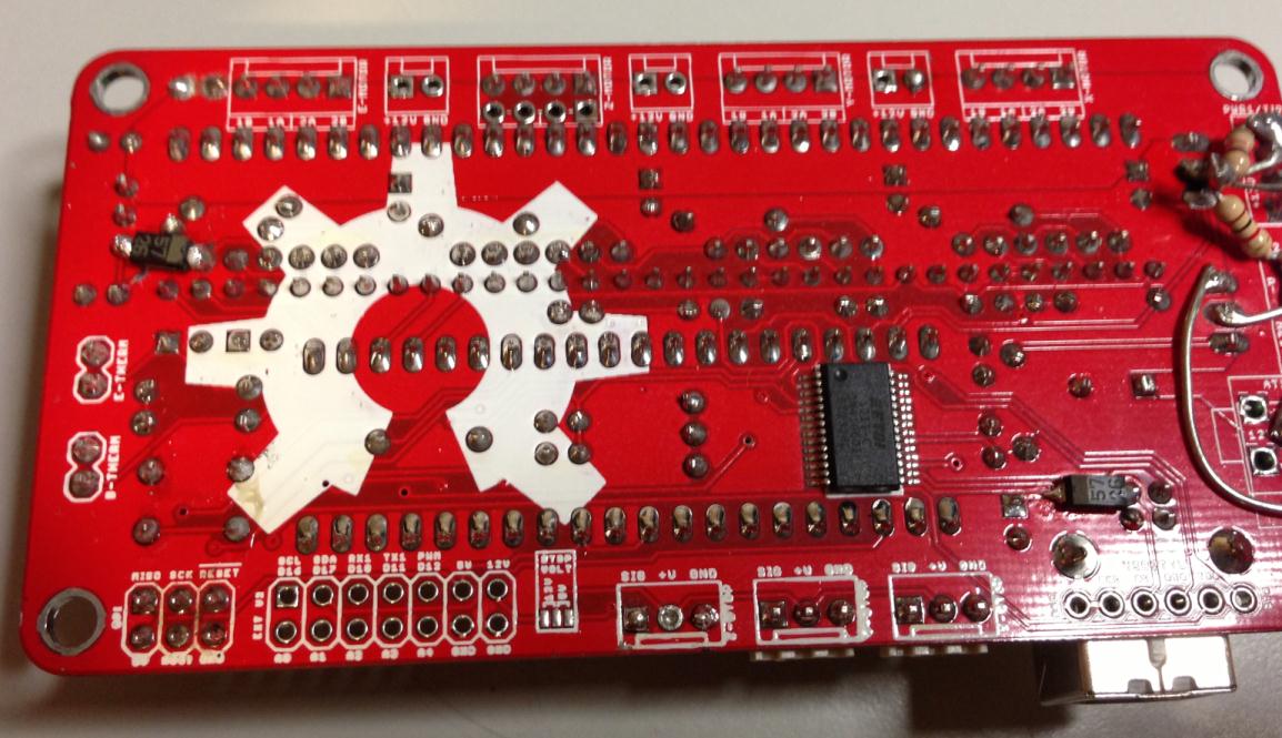
I had done something similar to my Sanguino, but put the diode on the 5V output of the regulator instead of the input. I used these surface mount schottky diodes and soldered them as shown in the attached picture. I also cut the traces underneath them to place them in-line.
I'm not sure if it's better to place the diode on the 12v side or the 5v side of the regulator, but can verify that my Sanguino has been working quite well for the past year with this implementation.
I'm not sure if it's better to place the diode on the 12v side or the 5v side of the regulator, but can verify that my Sanguino has been working quite well for the past year with this implementation.
|
Re: My mods for curing 5V USB/7805 problems on Sanguinololu 1.3a September 02, 2014 03:46PM |
Registered: 9 years ago Posts: 590 |
It's good to see that we both approached the problem in (almost) the same way 
If the diode is on the 5V side of the regulator, it decreases the 5V by the diode's forward voltage, whereas if it's on the 12V input side, it doesn't affect the 5V regulated output. But, of course, the diode we both put in the USB 5V line also decreases the 5V in that same way. One advantage of having the diode on the 7805 output is that it avoids the small current drain (just a few mA) through the regulator from 5V to ground when it is not connected to 12V input. So I guess from a practical point of view it does not matter if the diode is on the input or output side of the regulator - both versions solve the problem!
If the diode is on the 5V side of the regulator, it decreases the 5V by the diode's forward voltage, whereas if it's on the 12V input side, it doesn't affect the 5V regulated output. But, of course, the diode we both put in the USB 5V line also decreases the 5V in that same way. One advantage of having the diode on the 7805 output is that it avoids the small current drain (just a few mA) through the regulator from 5V to ground when it is not connected to 12V input. So I guess from a practical point of view it does not matter if the diode is on the input or output side of the regulator - both versions solve the problem!
|
Re: My mods for curing 5V USB/7805 problems on Sanguinololu 1.3a October 23, 2014 08:24AM |
Registered: 9 years ago Posts: 9 |
|
Re: My mods for curing 5V USB/7805 problems on Sanguinololu 1.3a October 23, 2014 12:18PM |
Registered: 9 years ago Posts: 590 |
|
Re: My mods for curing 5V USB/7805 problems on Sanguinololu 1.3a October 23, 2014 01:27PM |
Registered: 10 years ago Posts: 92 |
As @enif said, the schottky diodes prevent too much voltage drop across them. Give standard ones a shot if that's what you've got. They don't need to be particularly heavy duty or anything. Low forward voltage is the primary spec of interest.
I'm interested in what you meant by "the problem was not solved." Is the regulator still getting unreasonably hot? Or are you finding that you can't now talk to your sanguino?
If the regulator is getting really hot (and you're not getting 5V on your board when 12V is applied) you may have something wrong on your 5V bus.
As for talking to the sanguino:
If you're okay with keeping 12V applied to the board whenever you want to use it, there should be no problem with cutting the USB 5V.
Alternatively, if you're okay with always needing USB connected for the board to function, there should be no problem with cutting the trace from the regulator.
But cutting both traces without installing diodes would remove the 5V bus entirely, so nothing would work.
The diodes are more of a fix to make both of these scenarios work.
|
Re: My mods for curing 5V USB/7805 problems on Sanguinololu 1.3a October 23, 2014 03:47PM |
Registered: 9 years ago Posts: 9 |
OK.
I've got a couple of standard diodes but the forward voltage is about 1V. Is that too much?
By "problem not solved" I mean it is still burning hot, even without USB connected. I did cut the trace near the USB and now I need the 12V supply to connect. I cut the ´first´ two trace lines, same as @enif.
Worth mentioning is that I just fixed a damaged pin at the ATmega chip by remapping the thermistor circuits to an expansion port, this with @nophead's help. Damage was caused by dropping a metal object on the board while connected. I don't think anything else was damaged because everything is working now.
|
Re: My mods for curing 5V USB/7805 problems on Sanguinololu 1.3a October 24, 2014 09:28AM |
Registered: 9 years ago Posts: 590 |
At the input of the 7805 the forward voltage is no problem at all, since anyway we have to drop ~7V at the linear regulator. With only the USB input, the 1V drop is probably still ok, if the BOD (brown-out detection) fuses of the AtMega644/1284 are set to 2.7V. If BOD is set to 4.3V your USB port would have to deliver 5.3V. In any case, as soon as the 12V are connected, it should certainly work.
|
Re: My mods for curing 5V USB/7805 problems on Sanguinololu 1.3a October 24, 2014 10:49AM |
Registered: 10 years ago Posts: 92 |
@enif, do you have any thoughts on how changing the voltage might impact the thermistor readings? Since the thermistors are based on a voltage divider down from the 5V bus, would the ADCs read the same for the 4V supply (after diode drop) as for the 5V?
I'm not so familiar with how the ATMEGA's ADCs work--if they're based on some internal reference voltage it would seem that your measured temperatures would vary wildly depending on if there was 4V or 5V.
Of course, when it comes down to it, the only time the thermistor readings would really matter would be when you have 12V applied anyway, so it might not be an issue.
|
Re: My mods for curing 5V USB/7805 problems on Sanguinololu 1.3a October 24, 2014 12:04PM |
Registered: 9 years ago Posts: 590 |
@maso: As long as the termistors are read while the printer is running (which is the normal case), the diodes do not matter, since then the 5V are coming from the 7805 regulator. On the contrary, using the diode on the USB 5V lowers that voltage to below 5V, even if the USB port delivers a bit more than 5V. Thus, there is no current flowing into the Sanguinololu, so that the 5V are coming entirely from the regulated 7805 output. Only if the 12V are off, the 5V would become Vusb-Vdiode, so that would only be when the print is finished, the power supply is switched of and you watch how the hotend and bed are cooling down... But even the, the temperature readings should not be affected by the 5V variation: I looked at the Marlin source, and from what I can see (can anyone confirm?), all analog inputs seem to use AVcc (i.e. the "5V" rail) as reference voltage. So a variation of the 5V would not matter anyway, since the analog reading and the external voltage divider use the same reference.
|
Re: My mods for curing 5V USB/7805 problems on Sanguinololu 1.3a October 24, 2014 12:21PM |
Registered: 10 years ago Posts: 92 |
Yeah, that answers my question.
I was wondering if you could read the thermistors with the vUSB - vDIODE = 4V powering it, then apply 12V and, now that a full 5V is being provided, see that thermistor reading change.
Sounds like if it's referenced from the source it'll just be a percentage of that source anyway. Cool!
I was wondering if you could read the thermistors with the vUSB - vDIODE = 4V powering it, then apply 12V and, now that a full 5V is being provided, see that thermistor reading change.
Sounds like if it's referenced from the source it'll just be a percentage of that source anyway. Cool!
|
Re: My mods for curing 5V USB/7805 problems on Sanguinololu 1.3a October 24, 2014 04:28PM |
Registered: 9 years ago Posts: 9 |
I've found a nice online store to buy the schottky diodes. The BAT42 spec says: voltage drop 0.4V, voltage 30V, current 0.2A. Will it work? What is the maximum current running?
I think I will buy a voltage regulator as spare part, now that I'm ordering stuff. Then I need to know the max. output current.
Any thoughts about why my regulator is still hot?
Edited 1 time(s). Last edit at 10/24/2014 04:54PM by floppy.
I think I will buy a voltage regulator as spare part, now that I'm ordering stuff. Then I need to know the max. output current.
Any thoughts about why my regulator is still hot?
Edited 1 time(s). Last edit at 10/24/2014 04:54PM by floppy.
|
Re: My mods for curing 5V USB/7805 problems on Sanguinololu 1.3a October 24, 2014 05:24PM |
Registered: 9 years ago Posts: 590 |
200mA for the 5V rail should in principle(!) be fine. I use BAT43 here (which have the same max. current) without ever having had any problems.
BUT if your regulator gets hot, you might have some drain somewhere on the 5V rail, so that might cause a problem for the BAT42. Have you measured how much current the board draws from the 12V input when no load (motors, extruder, bed, fans...) is connected?
BUT if your regulator gets hot, you might have some drain somewhere on the 5V rail, so that might cause a problem for the BAT42. Have you measured how much current the board draws from the 12V input when no load (motors, extruder, bed, fans...) is connected?
|
Re: My mods for curing 5V USB/7805 problems on Sanguinololu 1.3a October 24, 2014 08:42PM |
Registered: 9 years ago Posts: 9 |
I haven't measured the current, only voltage. To do it, I have to break the circuit somewhere, right? I can't just touch two points.
Edit: I measured in series with the input 12V screw terminal and the power source. It was about 135mA.
How can I locate this drain? I have disconnected everything and it gets hot. No other component is hot, not even warm. Perhaps something under the stepper drivers.
About the diode, I can buy a 20/30V with 1A just to be sure. Three times the price though.
Edited 1 time(s). Last edit at 10/24/2014 09:15PM by floppy.
|
Re: My mods for curing 5V USB/7805 problems on Sanguinololu 1.3a October 25, 2014 01:58AM |
Registered: 9 years ago Posts: 590 |
135mA through the 7805 will roughly give 1W (7V*.135A), so it should not really get that hot...
I just measured my Sanguinololu with the stepsticks installed, but with nothing connected: Powered via USB I measure 31mA and via 13.9V on the 12V input it takes 50mA.
Might it be that one of the digital outputs of the AtMega chip is shorted? If you take out the stepsticks, do you still get the 135mA? Do the 135mA change wenn you plug in/out USB?
|
Re: My mods for curing 5V USB/7805 problems on Sanguinololu 1.3a October 25, 2014 07:20AM |
Registered: 9 years ago Posts: 9 |
|
Re: My mods for curing 5V USB/7805 problems on Sanguinololu 1.3a October 25, 2014 07:45AM |
Registered: 9 years ago Posts: 590 |
|
Re: My mods for curing 5V USB/7805 problems on Sanguinololu 1.3a October 25, 2014 08:03AM |
Registered: 9 years ago Posts: 9 |
|
Re: My mods for curing 5V USB/7805 problems on Sanguinololu 1.3a October 25, 2014 08:35AM |
Registered: 9 years ago Posts: 590 |
|
Re: My mods for curing 5V USB/7805 problems on Sanguinololu 1.3a October 25, 2014 08:47AM |
Registered: 9 years ago Posts: 9 |
|
Re: My mods for curing 5V USB/7805 problems on Sanguinololu 1.3a October 25, 2014 09:39AM |
Registered: 9 years ago Posts: 590 |
|
Re: My mods for curing 5V USB/7805 problems on Sanguinololu 1.3a October 25, 2014 09:54AM |
Registered: 9 years ago Posts: 9 |
|
Re: My mods for curing 5V USB/7805 problems on Sanguinololu 1.3a October 25, 2014 10:23AM |
Registered: 9 years ago Posts: 590 |
If you suspect that the 7805 is the problem, then why not just take it out and run the 5V rail only from USB. As long as you have both USB and 12V connected the Sanguinololu should still work fine. You can then connect the bare 7805 to the 12V and GND (leaving 5V output open), if it still gets hot, you'll know that the 7805 is the problem.
|
Re: My mods for curing 5V USB/7805 problems on Sanguinololu 1.3a October 25, 2014 02:35PM |
Registered: 9 years ago Posts: 9 |
I removed the regulator but it was harder than it should be. The middle pin didn't want to desolder at all. Had to break it off and force the remains out with the soldering iron. I tried to reconnect it again as you said but I didn't solder and the connection might have been bad, anyway it didn't get hot.
Now with the USB powering the 5V rail I get about 4.75V. I think i got 4.96 or something before, not sure.
Will it be good enough with only USB power and will it be steady?
Now with the USB powering the 5V rail I get about 4.75V. I think i got 4.96 or something before, not sure.
Will it be good enough with only USB power and will it be steady?
|
Re: My mods for curing 5V USB/7805 problems on Sanguinololu 1.3a October 25, 2014 05:36PM |
Registered: 9 years ago Posts: 590 |
|
Re: My mods for curing 5V USB/7805 problems on Sanguinololu 1.3a April 24, 2015 04:16AM |
Registered: 10 years ago Posts: 13 |
Hello...
Just one comment here...
Backfeeding 7805 is not good idea at all!. Read the datasheet!
May work but how long. In 7805 there is reverse path that can be destroyed with high current. So if you have 7805 with only (empty) 100nF capacitor on input and you apply 5V to output terminal there is "unlimited" inrush current flow backward to charge 100nF capacitor on input. So it's depends on how capable the source is. If you feed that from computer with 1.5m long cable (low quality one with thin wires) there should be no problem at all. But if you feed that from powered USB hub (or power capable computer) with short USB cable (good quality one) then you can blow the regulator. I do test on workbench and one regulator was killed instantly other one was survived few times then blow up. And Both was blown up in the way that will supply 5V rail unregulated (from 12V) so to kill all other components. And I do some more tests what 7805 can survive. And belive me that can be destroyed only from backfeeding or overvoltage.
So to solve problem we can:
-Power FTDI chip from USB and cut 5V line to other electronics.
*-drawback there are no resistors in RX and TX lines from FTDI to ATMEGA and the lines are overloaded.
-Insert diode from 5V pin on USB connector to the rail, and insert diode from 7805 regulator.
*-drawback the 5V rail is aprox 0.25V lower. Should not cause problem. Even temperature reading should work but didn't test that.
*-drawback the current is limited to 200mA with BAT43 or similar diodes. 1N58xx have little more voltage drop but can handle full current from 7805.
And there is another one trouble.
A lot of users get usb disconnect/reconnect when printer is turned on, or some other heavy load. The cause is ground loop current. If you have connected computer in one socket and printer in other there can be hughe current flowing in ground wire. (low voltage vut high current path)
The solution is isolated USB port. You can buy it ready made. The other way is to incorporate that on board.
For doing that we need two 6N137 photocouplers and 4 resistors. This is ultimate solution but need redesign of PCB. It solve Ground loop current AND backfeeding +5V line.
...litle more than 2 cents from me
|
Re: My mods for curing 5V USB/7805 problems on Sanguinololu 1.3a June 23, 2019 03:05PM |
Registered: 4 years ago Posts: 2 |
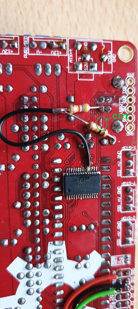
I made a cut at the 5V USB Trace, and added a 4k7 and a 10k Resistor as in the Datasheet of the FT232RL (6.2 Self- Powered) and soldered a wire to pin 19
The datasheet can be found at: [www.ftdichip.com]
Works great but the printer has to be powered by 12V all the Time.
The datasheet can be found at: [www.ftdichip.com]
Works great but the printer has to be powered by 12V all the Time.
|
Re: My mods for curing 5V USB/7805 problems on Sanguinololu 1.3a September 20, 2020 12:56PM |
Registered: 3 years ago Posts: 2 |
|
Re: My mods for curing 5V USB/7805 problems on Sanguinololu 1.3a September 20, 2020 01:07PM |
Registered: 4 years ago Posts: 2 |

Sorry, only registered users may post in this forum.