Did anyone used linear hall sensors on BLDCs for position sensing?
Posted by misan
|
Did anyone used linear hall sensors on BLDCs for position sensing? June 05, 2015 02:14PM |
Registered: 12 years ago Posts: 972 |
I am searching for a suitable solution for using DC motors (actually BLDC) to create closed-loop position controls that could replace/improve over the steppers we use in most of our 3D printers.
While I do have several motors running successfully with my code: [www.youmagine.com] one key part of this quest is to get the price right. Not many are going to buy a $100 motor just to keep their printers from skipping a step occasionally.
So I am working to get the cost down to a similar level than a stepper plus its drive electronics (at around $15 each).
All my tests so far have use incremental encoders for providing position feedback.
But recently the use of linear hall sensors to both help with BLDC conmutation and figure out the shaft position without the need of an encoder have been brought up to my attention.
So here is my question to you guys: have you used linear hall sensors to replace an incremental encoder with success?
I have found a paper that suggests it can be done easily: [homes.cs.washington.edu] but I will be more confident if a fellow reprapper already tested that solution space.
Suffice is to say that dropping the encoder will further decrese the cost of such a closed-loop BLDC contraption.
Thanks a lot,
misan
|
Re: Did anyone used linear hall sensors on BLDCs for position sensing? June 06, 2015 07:24PM |
Registered: 9 years ago Posts: 977 |
Hi Misan,
I read the paper that you linked to, and I can see a couple of major obstacles to bringing the price point of a brushless DC motor with closed loop positioning based on linear hall effect sensors down to the $15 price point that we are used to with our basic NEMA 17 steppers.
1. The price of adding the many required linear hall effect sensors to any brushless DC motor assembly is not negligible. First, quite a few sensors are required, second, they must be precisely positioned, and third, each additional sensor requires wires which have to connect to the closed loop control circuit. And of course, each sensor/wire/component adds one more failure point to a mechanical device designed to operate thousands of hours. All that is not easy to do cheaply.
2. The closed loop control circuit for each brushless DC motor appears to require as much (real-time) processing power or even more than our very basic 8-bit AVR MCU - that presently controls an entire 3D printer - can provide. So basically for a five-stepper Prusa i3 we would require five 32-bit MCUs just for the control loops. And again, we are adding quite a few more failure points to our 3D printers.
3. One of the details that the paper brushes over (pun intended) is that each individual linear hall effect sensor needs to be calibrated separately and requires a properly designed analog amplifier circuitry for signal conditioning. Again, more costs and more failure points.
Of course I find the idea of closed loop control of rotary or linear motion actuators extremely attractive, but I am guessing the reason servo motors for e.g. CNC applications are so expensive is that there is no known way to make them any cheaper.
|
Re: Did anyone used linear hall sensors on BLDCs for position sensing? June 07, 2015 04:44AM |
Registered: 12 years ago Posts: 972 |
HI AndrewBCN,
Good points, let me elaborate on them.
[/quote]
Anyway, my point is to open the discussion and the exchange of ideas and experiences. If it were easy it alredy would be done
I already have a working solution for either brushed DC motors or for brushless motors with built-in encoder and drive electronics that I shared openly in the link above within the cost limit I mentioned, but I am interested on alternatives that could be cheaper and/or better.
Good points, let me elaborate on them.
I have been using optical incremental encoder successfully but motor manufacturer suggested this idea that would replace the three Hall sensors used for commutation by three linear Hall-effect sensors. Depending on rotors number of poles the sensors will recreate more than one cycle per rotor revolution. If an encoder can be had for $3, I expect this change to be cheaper than that.Quote
AndrewBCN
1. The price of adding the many required linear hall effect sensors to any brushless DC motor assembly is not negligible. First, quite a few sensors are required, second, they must be precisely positioned, and third, each additional sensor requires wires which have to connect to the closed loop control circuit. And of course, each sensor/wire/component adds one more failure point to a mechanical device designed to operate thousands of hours. All that is not easy to do cheaply.
It is true that field oriented control, using Clarke transform, can be too much for an 8-bit microcontroller. We can use a not so fine control or stick to inexpensive 32-bit MCUs. One advantage in this application is that high-speed is not needed, which cut us some slack.Quote
AndrewBCN
2. The closed loop control circuit for each brushless DC motor appears to require as much (real-time) processing power or even more than our very basic 8-bit AVR MCU - that presently controls an entire 3D printer - can provide. So basically for a five-stepper Prusa i3 we would require five 32-bit MCUs just for the control loops. And again, we are adding quite a few more failure points to our 3D printers.
[/quote]
This may be the reason that could kill the idea at the start: If such a calibration cannot be done easily by either the manufacturer or by the motor controller, then we might have a problem. Given that PID controller will need to be adjusted for each motor anyway, I would assume that a self-tunning mode will need to be triggered on the first use of the motor or every time it is added to a different axis/printer. Hopefully such self-tunning should include a Hall sensors calibration process.Quote
AndrewBCN
3. One of the details that the paper brushes over (pun intended) is that each individual linear hall effect sensor needs to be calibrated separately and requires a properly designed analog amplifier circuitry for signal conditioning. Again, more costs and more failure points.
It's getting cheaper lately, on one hand Tecnik Clear Path line is getting more affordable for CNC applications, and it can get much cheaper if you use smaller motors and some ingenuity, like adding an encoder with a sensorless brushless motor [cache.freescale.com] . One implementation example for CNC may be this [www.cnczone.com]Quote
AndrewBCN
Of course I find the idea of closed loop control of rotary or linear motion actuators extremely attractive, but I am guessing the reason servo motors for e.g. CNC applications are so expensive is that there is no known way to make them any cheaper.
Anyway, my point is to open the discussion and the exchange of ideas and experiences. If it were easy it alredy would be done
I already have a working solution for either brushed DC motors or for brushless motors with built-in encoder and drive electronics that I shared openly in the link above within the cost limit I mentioned, but I am interested on alternatives that could be cheaper and/or better.
|
Re: Did anyone used linear hall sensors on BLDCs for position sensing? June 07, 2015 06:38AM |
Registered: 9 years ago Posts: 977 |
Hello Misan
I have checked the all-in-one ClearPath brushless servo system and while I find the technology very impressive, their prices are stated to be around $250 for a NEMA 23 sized servo.
I have also checked the thread at cnczone.com, very interesting, although again, this all seems to be at a very experimental stage and still a few years away from the point where it can be applied to our RepRap 3D printers or home CNC machines.
Regarding the linear hall sensors, I confess I prefer by far a simple optical encoder solution which provides a direct binary output, instead of an analog value that requires a precisely calibrated, temperature-stable and noise proof amplifier as well as an ADC channel and additional processing muscle.
I see you are using this combined motor+optical encoder in your prototype and I checked its price on AliExpress, it's < $30. It also only requires an 8-bit AVR MCU for closed-loop control.
I really think that kind of solution is more likely to be less expensive to manufacture and implement than the linear hall sensor-based ones. Obviously for CNC applications we would need a properly dust-sealed assembly, which adds to the cost, and partly explains the price of the ClearPath solutions.
Frankly Misan, I admire you for your pioneering work in this area, I hope you don't mind my comments above which may have sounded a little bit negative, I am afraid.
To summarize, I think the optical encoder solution, properly sealed, is the way to go here, simply because it offers a digital output and does not require any analog glue circuitry and ADC conversion and postprocessing.
I have checked the all-in-one ClearPath brushless servo system and while I find the technology very impressive, their prices are stated to be around $250 for a NEMA 23 sized servo.
I have also checked the thread at cnczone.com, very interesting, although again, this all seems to be at a very experimental stage and still a few years away from the point where it can be applied to our RepRap 3D printers or home CNC machines.
Regarding the linear hall sensors, I confess I prefer by far a simple optical encoder solution which provides a direct binary output, instead of an analog value that requires a precisely calibrated, temperature-stable and noise proof amplifier as well as an ADC channel and additional processing muscle.
I see you are using this combined motor+optical encoder in your prototype and I checked its price on AliExpress, it's < $30. It also only requires an 8-bit AVR MCU for closed-loop control.

I really think that kind of solution is more likely to be less expensive to manufacture and implement than the linear hall sensor-based ones. Obviously for CNC applications we would need a properly dust-sealed assembly, which adds to the cost, and partly explains the price of the ClearPath solutions.
Frankly Misan, I admire you for your pioneering work in this area, I hope you don't mind my comments above which may have sounded a little bit negative, I am afraid.
To summarize, I think the optical encoder solution, properly sealed, is the way to go here, simply because it offers a digital output and does not require any analog glue circuitry and ADC conversion and postprocessing.
|
Re: Did anyone used linear hall sensors on BLDCs for position sensing? June 07, 2015 07:21AM |
Registered: 12 years ago Posts: 972 |
Hi AndrewBCN,
Thank you for your kind words.
I have tested three motors I think could be used.
So I have ended up in talks with a manufacturer that seems interested and we are in the process of developing a brushless motor that will work at 12V and it should provide an easy replacement path for X & Y axis motors (just pull the Pololu and plug the motor wires instead). These motors would include drive electronics so interface uses the step, direction and enable pins that are standard on any stepper controller.
It is when trying to get the best price possible when we face with the idea of dropping the encoder, but as I am quite happy with how encoders work and I am doubtful about replacing them with other technology, I ask here to see if I get encourament or warning signs.
Thank you for your kind words.
I have tested three motors I think could be used.
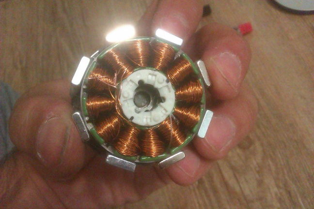
- The cheapest one was $5 but it was a MABUCHI 370 brushed motor [www.mabuchi-motor.co.jp] with 448 CPR incremental encoder. And included a 14-tooth MXL pulley. It seemed to be a bit short of torque at 12V but considering I was using an L298 for the drive electronics I guess that could be improved with more efficient drive. With 4x encoder readings we have almost 1800 "steps" per revolution, and if the original pulley is kept that turns into a resolution of 0.016mm/step. It is with these motors that I did this video [www.youtube.com]
- The second choice was a brushless motor, I later learned it is manufactured for Ricoh, that comes with built-in drive electronics (which makes our life simpler) and a 100 CPR encoder (that is the worst part, as it seems a bit poor for my taste). I have failed to obtain a datasheet but motor feels very powerful at 12V and impressive at 24V. There are two models a 10W and a 20W motor. But unfortunately they seem to be marketed by Shenzen sellers that somehow grab a bunch of them but have no idea what they are dealing with. I could buy both versions just under $15 each. But to the cost of the motor we still need to add the closed-loop processor. I managed to get two of these motors controlled by a single Arduino, that, if Pro Mini is chosen can be had at $1.5 each.
- The third choice is a brushless motor from Nidec, the 12V one from 24H series [www.nidec.com] . Again eBay sellers have no info or idea about what they sell and my unit arrived rusted on the outside (but operational). Nidec is a B2B manufacturer and unit prices are only available for manufacturers. Nidec motor has room in the drivers PCB for an encoder but my $7 unit did not have it on board. Though the motor is light, it delivers way more torque than Mabuchi's so I quite like it too. But I kind of rule it out as sourcing it seems sketchy too.
So I have ended up in talks with a manufacturer that seems interested and we are in the process of developing a brushless motor that will work at 12V and it should provide an easy replacement path for X & Y axis motors (just pull the Pololu and plug the motor wires instead). These motors would include drive electronics so interface uses the step, direction and enable pins that are standard on any stepper controller.
It is when trying to get the best price possible when we face with the idea of dropping the encoder, but as I am quite happy with how encoders work and I am doubtful about replacing them with other technology, I ask here to see if I get encourament or warning signs.
|
Re: Did anyone used linear hall sensors on BLDCs for position sensing? June 07, 2015 08:05AM |
Registered: 9 years ago Posts: 977 |
Misan,
I found this on YouTube: [www.youtube.com]
This AS5134 chip seems to integrate every component required and only needs a single 2-pole magnet rotating over the center of the chip to function, so that effectively removes all my previous reservations about the use of hall effect sensors. Resolution is 8.5 bits i.e. 360cpr. You can ask austriamicrosystems for a list of compatible magnets.
[ams.com]
You may want to check prices, ask for an engineering sample and whether austriamicrosystems is willing to lend some field production engineering to your BLDC design to integrate their chip.
|
Re: Did anyone used linear hall sensors on BLDCs for position sensing? June 07, 2015 09:37AM |
Registered: 12 years ago Posts: 972 |
|
Re: Did anyone used linear hall sensors on BLDCs for position sensing? June 07, 2015 01:20PM |
Registered: 9 years ago Posts: 346 |
Hello Misan,
What is the advantage of using a brushless DC motor instead of a stepper? Is it a cost reduction aim that you are looking for? Or is it size?
I have some time ago ordered a number of various hall chips to try and do what you do, so I am really interested in your work. My aim is size reduction and absolute position.
I would like to make a printer (coreXY type) but with only the hotend moving up and down in Z direction. I only need to move ~50 mm up and down. For this purpose I need a small, light and powerful motor with high step resolution and with absolute position because I need to compensates for the non-linearities in it's movement.
You can see a picture of my early design here:
[lh3.googleusercontent.com]
Actually my plan these days is to use it for a laser instead of a hotend at first. For this reason I really need high precision because the focal distance needs to be perfect to get smallest burn spot.
Unfortunately I have so far made zero progress besides buying some SS543-AT chips - For test and verification a 600 pulse optical encoder for calibration and test purpose. No motor selected yet.
About calibration - One solution is to use a lot of gears and let the motor run fast. The idea is that as long as we get the RPM right it does not matter if our sensor is reporting 10% too much or too little at some given degree in between because the error will be flattened out with the gears. We can also use cheap plastic gears running a shaft where we mount the magnet so that one rotation on the motor (running directly the printer) gives 10 rotation on our shaft with the magnet - Thus also flattening out the error.
|
Re: Did anyone used linear hall sensors on BLDCs for position sensing? June 07, 2015 01:46PM |
Registered: 9 years ago Posts: 977 |
Quote
LarsK
What is the advantage of using a brushless DC motor instead of a stepper? Is it a cost reduction aim that you are looking for? Or is it size?
...
The point here is to "close the loop" i.e. to get positional feedback. Besides that, BLDC's are available in all sizes and power ratings imaginable from thousands of manufacturers at rock-bottom prices, they can be built to pretty tough specifications, and the technology is totally mature (but all that also applies to steppers).
|
Re: Did anyone used linear hall sensors on BLDCs for position sensing? June 07, 2015 02:17PM |
Registered: 12 years ago Posts: 972 |
The advantage of using a closed-loop system is to compensate for potential errors, that means no more missed steps.
Cost reduction is not a goal, but we are trying to get this working within a similar cost range as steppers. This solution space has been explored, tested and discarded in the past for RepRap mostly because of its high cost. That is why I am so conscious about its potential cost.
You should get better linearity from a closed-loop position control than from a stepper.
|
Re: Did anyone used linear hall sensors on BLDCs for position sensing? June 07, 2015 03:09PM |
Registered: 9 years ago Posts: 346 |
Quote
misan
The advantage of using a closed-loop system is to compensate for potential errors, that means no more missed steps.
Cost reduction is not a goal, but we are trying to get this working within a similar cost range as steppers. This solution space has been explored, tested and discarded in the past for RepRap mostly because of its high cost. That is why I am so conscious about its potential cost.
You should get better linearity from a closed-loop position control than from a stepper.
Hello both you Misan and AndrewBCN,
Misan, I do not understand why missed steps is a concern. I don't say this out of arrogance but I am fairly late to the 3d printing world - SO what I would say is that, if your 3d printer is missing steps, it is because it is not designed properly or is in need of maintenance. The only time I see my printers (Delta and a CoreXY) missing steps is when something is terribly off - Such as wrong heights so it is hitting the sides. Am I misleading my self here?
I DO realize that the potential intelligence that you can build into your system with closed loop is significant. For example if your printer hits the side you can have it go back 5 steps and then forward again and if that still does not do any good it stops moving. And more sophisticated you can implement some control schemes which handles the dynamics in high speed printing much better. Especially adaptive algorithms that based on some acceptable errors intervals can optimize the regulation parameters for perfect jerk moves. This will especially be relevant with future heavier multi-color extruders.
Finally for applications like mine and for future miniature printers where it is desirable to have very small and light motors. This could also be to solve the elasticity problem of bowden extruders. If you can cut the weight in half of the extruder then it may be more acceptable to have it together with the hotend.
Why did inkjet printers move from steppers to servos? Was it a necessity because of the demands on modern inject controls or was it simply the price?
On the same topic I found the following on [www.amci.com]
"steppers are simpler to commission and maintain than servos. They are less expensive, especially in small motor applications. They don't lose steps or require encoders if operated within their design limits. Steppers are stable at rest and hold their position without any fluctuation, especially with dynamic loads.
Servos are excellent in applications requiring speeds greater than 2,000 RPM and for high torque at high speeds or requiring high dynamic response. Steppers are excellent at speeds less than 2,000 RPM and for low to medium acceleration rates and for high holding torque.
Stepper vs. Servo: The Verdict
Servo control systems are best suited to high speed, high torque applications that involve dynamic load changes. Stepper control systems are less expensive and are optimal for applications that require low-to-medium acceleration, high holding torque, and the flexibility of open or closed loop operation."
|
Re: Did anyone used linear hall sensors on BLDCs for position sensing? June 07, 2015 03:42PM |
Registered: 12 years ago Posts: 972 |
Hi LarsK,
Your question is pertinent: If system parameters are within reason, missing steps is an unlike event. However, things are at times slightly off and trouble may happen: a small plastic blob that may block the nozzle for a moment triggering a bad print, a hotend that presents momentarily a bit more backpressure and thus fewer plastic is deposited leading to de-lamination of the part later, dirt on the rods that requires now more torque from the motors that when the system was built, etc
The reason 2d printers switch from steppers to DC motors is two-fold: lower cost of the motor and lower power consumption (which in turn will reduce the cost of the power supply). But beyond cost issues, using a closed-loop system provided them higher resolution and better linearity. Both features could be welcome in a RepRap near us too.
Minute printers like M3D are already using DC motors in closed loop. [printm3d.com]
There are some advantages of servos that we might brougt in later (but are not now the driving factor) like end-stop emulation (you could have max and min endstop for free from the motor controller when it detects it bumped into each side ie. overcurrent), lower current consumption, quieter operation or smoother motion that might make possible better quality prints (I am speculating here).
But the main point of discussing the matter openly is to test the ideas and to enrich our knowledge with other people's ideas. So once again, thanks for chiming in.
Quote
LarsK
Misan, I do not understand why missed steps is a concern. I don't say this out of arrogance but I am fairly late to the 3d printing world - SO what I would say is that, if your 3d printer is missing steps, it is because it is not designed properly or is in need of maintenance. The only time I see my printers (Delta and a CoreXY) missing steps is when something is terribly off - Such as wrong heights so it is hitting the sides. Am I misleading my self here?
Your question is pertinent: If system parameters are within reason, missing steps is an unlike event. However, things are at times slightly off and trouble may happen: a small plastic blob that may block the nozzle for a moment triggering a bad print, a hotend that presents momentarily a bit more backpressure and thus fewer plastic is deposited leading to de-lamination of the part later, dirt on the rods that requires now more torque from the motors that when the system was built, etc
The reason 2d printers switch from steppers to DC motors is two-fold: lower cost of the motor and lower power consumption (which in turn will reduce the cost of the power supply). But beyond cost issues, using a closed-loop system provided them higher resolution and better linearity. Both features could be welcome in a RepRap near us too.
Minute printers like M3D are already using DC motors in closed loop. [printm3d.com]
There are some advantages of servos that we might brougt in later (but are not now the driving factor) like end-stop emulation (you could have max and min endstop for free from the motor controller when it detects it bumped into each side ie. overcurrent), lower current consumption, quieter operation or smoother motion that might make possible better quality prints (I am speculating here).
But the main point of discussing the matter openly is to test the ideas and to enrich our knowledge with other people's ideas. So once again, thanks for chiming in.
|
Re: Did anyone used linear hall sensors on BLDCs for position sensing? June 07, 2015 03:58PM |
Registered: 9 years ago Posts: 977 |
@ LarsK
I am thinking the text you quoted is probably out of date. I cannot think of a single situation nowadays in which an open-loop stepper-based solution can offer better performance than a comparable-sized closed-loop digital servo solution. The only thing is, the digital servo solution is likely to cost 5 to 10 x as much as the stepper based one.
As Misan wrote above, he is exploring a different solution space to the problem of linear or rotary actuators than the open-loop steppers-based solution space we are used to.
If we can get digital BLDC servos to approach the price range of same-size steppers with same or higher resolution, this could be revolutionary, not only for RepRap 3D printing, but also for DIY CNC and actually any kind of DIY robot.
As far as I know industrial CNC machinery and robot manufacturers have abandoned open-loop stepper based motion for closed-loop (servo) actuators en masse, because they are not as cost-bound as we RepRappers are, and a closed-loop approach can do pretty much anything an open-loop one can, only better.
Edited 1 time(s). Last edit at 06/07/2015 03:58PM by AndrewBCN.
|
Re: Did anyone used linear hall sensors on BLDCs for position sensing? June 20, 2015 10:16PM |
Registered: 8 years ago Posts: 1 |
I worked on a much larger solar car motor (3 phase synchronous AC) and used the AS5048A for position sensing. It worked pretty well, although care must be taken to adequately shield the very high speed SPI lines from the sensor.
I think this type of sensor could work very well for closed loop control, and have been toying with the idea for a while. It could work both for a stepper motor, brushed DC motor, or 3 phase AC motor. In this context a stepper motor is basically a 2 phase AC motor.
You get a couple of advantages from position feedback. One is the obvious "no more missed steps". A more important advantage, in my opinion, is that you can do field oriented control. Maximum torque is always achieved by applying a flux 90 degrees out of phase from the rotor flux. Normal stepper drive does not do this, leading to very high vibration and wasted power / heat. The rotor flux corresponds to the position of the rotor (not exactly for hybrid steppers and IPM drives, but close), so a sensor makes it easy to do this properly.
I've been looking at a possible implementation of this consisting of a PCB containing the sensor, as well as the motor driver, mounted to the back of a stepper. The sensor magnet would be glued to the end of the shaft - a dual ended stepper would be preferred, but even single ended ones usually have the shaft exposed. I think using a traditional bipolar stepper would be a good place to start, because they are very common, rated for continuous stalling, and can easily fall back to open-loop drive.
|
BLDC design August 01, 2015 12:31PM |
Registered: 8 years ago Posts: 1 |
hello all guys
i am new .this post is the first one.
i am working on BLDC motors and try to make and design some.
i need to know how is possible to make the max torque near max speed? ( by changing in winding turn or diameter I think )
Edited 1 time(s). Last edit at 08/01/2015 12:32PM by kasra_sa.
i am new .this post is the first one.
i am working on BLDC motors and try to make and design some.
i need to know how is possible to make the max torque near max speed? ( by changing in winding turn or diameter I think )
Edited 1 time(s). Last edit at 08/01/2015 12:32PM by kasra_sa.
|
Re: Did anyone used linear hall sensors on BLDCs for position sensing? August 01, 2015 01:24PM |
Registered: 11 years ago Posts: 5,780 |
Some BLDC motors have hall effect sensors built in and the signals are used by the driver chip to regulate speed, etc. I have a blower from a CPAP machine (from American Science and Surplus) that cost $9 that has a 3 phase BLDC with 3 hall effect sensors. I have seen driver chips for this type of motor that use the hall effect sensor signals as feedback to start up the motor and control the motor speed. I have driven that blower open-loop using a model airplane ESC (about $8 for a 25A Turnigy ESC) and a servo tester (another $5). It seems to me you could grab one of the Hall effect sensor signals and use it to monitor motor revs/speed, and use a uC to provide a PWM signal to the driver chip.
Every cheap BLDC motor I have seen is designed for very high speed (model airplane and helicopter props, fans, etc.). I wonder what happens to torque when you run at the very low speeds 3D printers typically use.
Here is video of an ESC driven blower running open loop at 12V and about 5A (this one has no Hall effect sensors): [vimeo.com]
The blower is 80mm diameter.
Edited 1 time(s). Last edit at 08/01/2015 01:25PM by the_digital_dentist.
Ultra MegaMax Dominator 3D printer: [drmrehorst.blogspot.com]
|
Re: BLDC design August 01, 2015 01:27PM |
Registered: 12 years ago Posts: 972 |
If I understand correctly, torque is proportional to coil current, so theoretically you could get the desired torque at any speed as far as you can supply the desired current to the windings. Unfortunately, there are two reasons that is not possible:
1) the cycle time a coils is energized is reduced as rotational speed increases, this makes it more difficult to achieve the desired coil current, specially when you have a voltage limited power supply.
2) the rotation of the motor induces a an opposite voltage on the coils (counter electromotive force) that reduce the maximum current that go through the coils. That effect is more important the faster the rotation speed is, thus limiting the maximum speed the motor can reach.
So usually you are left with real motors, that achieve the maximum torque at low speeds, but with the proper control can keep a good torque value for higher speeds.
Still, given the fact that motor power is the product of torque times the rotational speed, it is easy to see that for a given power figure toque has to go down as speed goes up.
What you want to achieve is to set the maximum efficiency point at the desired maximum speed. The figure below shows a given motor behavior.
The maximum efficiency will happen when the relationship between the electrical power used and the mechanical power delivered is maximized. If you add turns to the coils you increase the torque at the expense of reducing the maxim speed.
1) the cycle time a coils is energized is reduced as rotational speed increases, this makes it more difficult to achieve the desired coil current, specially when you have a voltage limited power supply.
2) the rotation of the motor induces a an opposite voltage on the coils (counter electromotive force) that reduce the maximum current that go through the coils. That effect is more important the faster the rotation speed is, thus limiting the maximum speed the motor can reach.
So usually you are left with real motors, that achieve the maximum torque at low speeds, but with the proper control can keep a good torque value for higher speeds.
Still, given the fact that motor power is the product of torque times the rotational speed, it is easy to see that for a given power figure toque has to go down as speed goes up.
What you want to achieve is to set the maximum efficiency point at the desired maximum speed. The figure below shows a given motor behavior.

The maximum efficiency will happen when the relationship between the electrical power used and the mechanical power delivered is maximized. If you add turns to the coils you increase the torque at the expense of reducing the maxim speed.
|
Re: Did anyone used linear hall sensors on BLDCs for position sensing? August 01, 2015 01:40PM |
Registered: 12 years ago Posts: 972 |
Since I asked the question first I have gone through several tests. Working together with a motor manufacturer some samples were created including an additional linear hall sensor to the usual three digital sensors used for commutation. I cannot recommend that setup, as there is always to be one part of each turn where the linear sensor signal will be non-monotonic which will create a difficult to solve problem.
So the next stop is what TD-Linux suggests, to use one magnetic rotary sensor that can be had cheaper than an optical encoder with the added benefit of providing an absolute angle measurement (instead of the relative one provided by an incremental optical encoder).
I reckon I read that these magnetic encoders (by AMS) have already been used successfully by openservo project.
You can see a short video of what I am getting now using a brushless motor with an optical encoder [youtu.be]
Edited 3 time(s). Last edit at 08/01/2015 04:30PM by misan.
|
Re: BLDC design August 01, 2015 03:33PM |
Registered: 10 years ago Posts: 14,672 |
Quote
misan
If I understand correctly, torque is proportional to coil current...
For any particular permanent magnet motor, yes. More generally, for permanent magnet motors, it is proportional to the ampere-turns of the winding, i.e. the product of current and the number of turns. This applies to both steppers and BLDCs.
Quote
misan
, so theoretically you could get the desired torque at any speed as far as you can supply the desired current to the windings. Unfortunately, there are two reasons that is not possible:
1) the cycle time a coils is energized is reduced as rotational speed increases, this makes it more difficult to achieve the desired coil current, specially when you have a voltage limited power supply.
2) the rotation of the motor induces a an opposite voltage on the coils (counter electromotive force) that reduce the maximum current that go through the coils. That effect is more important the faster the rotation speed is, thus limiting the maximum speed the motor can reach.
Both of those can be countered by using constant current drive and increasing the drive voltage as necessary with increasing speed. But there is a third factor:
3) there is a maximum current (the rated current of the motor) that you can put through the windings without the motor overheating, because of the resistance of the windings. To allow more current, you have to make the motor bigger so that you can use thicker wire having lower resistance.
Quote
misan
So usually you are left with real motors, that achieve the maximum torque at low speeds, but with the proper control can keep a good torque value for higher speeds.
Real motors can maintain the same torque as you increase the speed, provided you increase the voltage to counter the back emf of the windings so as to maintain the current. Of course there is a limit to this, because eventually other effects become important such as bearing heating, the voltage being more than the insulation can stand, and increased losses in the electronics.
Quote
misan
... If you add turns to the coils you increase the torque at the expense of reducing the maxim speed.
No. If you add turns, you have to use thinner wire to fit the extra turns in, which increases resistance; hence you have to reduce the current - which to a first approximation (i.e. assuming that the same percentage of winding area is filled with copper in either case) exactly cancels out the effect of the extra turns on the torque. What you have done is to turn a high current low voltage motor into a lower current higher voltage motor.
Large delta printer [miscsolutions.wordpress.com], E3D tool changer, Robotdigg SCARA printer, Crane Quad and Ormerod
Disclosure: I design Duet electronics and work on RepRapFirmware, [duet3d.com].
|
Re: BLDC design August 01, 2015 04:08PM |
Registered: 12 years ago Posts: 972 |
Thanks dc42 for chiming in. I have tried to keep things simple but I mostly agree with your points.
While it does sound right, it may become ineffective due to 1) and the inductance of the coils.
On the other hand ...
Reducing the section of the wire will increase the resistive load and definitely will reduce motor speed and current consumption, even more so if besides you add more turns.
Quote
dc42
3) there is a maximum current (the rated current of the motor) that you can put through the windings without the motor overheating, because of the resistance of the windings. To allow more current, you have to make the motor bigger so that you can use thicker wire having lower resistance.
While it does sound right, it may become ineffective due to 1) and the inductance of the coils.
That is what I was suggesting with "with the proper control can keep a good torque value for higher speeds". I intentionally did not say the same torque due the difficulties of achieving a constant current at high speeds.Quote
dc42
Real motors can maintain the same torque as you increase the speed
On the other hand ...
if you add turns [of the same wire] you will increase the ampere-turns of the windings (as you mentioned) and that will give you more torque but it will reduce the max speed.Quote
dc42
If you add turns, you have to use thinner wire to fit the extra turns in...
Reducing the section of the wire will increase the resistive load and definitely will reduce motor speed and current consumption, even more so if besides you add more turns.
|
Re: BLDC design August 01, 2015 04:43PM |
Registered: 10 years ago Posts: 14,672 |
Quote
misan
On the other hand ...
if you add turns [of the same wire] you will increase the ampere-turns of the windings (as you mentioned) and that will give you more torque but it will reduce the max speed.Quote
dc42
If you add turns, you have to use thinner wire to fit the extra turns in...
True; but adding more turns means increasing the motor size to get more winding area (unless you started with a winding area that was only partially filled, which would be silly). And it will only reduce the max speed if you can't increase the drive voltage to compensate for the additional back emf.
Large delta printer [miscsolutions.wordpress.com], E3D tool changer, Robotdigg SCARA printer, Crane Quad and Ormerod
Disclosure: I design Duet electronics and work on RepRapFirmware, [duet3d.com].
|
Re: Did anyone used linear hall sensors on BLDCs for position sensing? March 29, 2016 03:53PM |
Registered: 10 years ago Posts: 9 |
Quote
misan
- The third choice is a brushless motor from Nidec, the 12V one from 24H series [www.nidec.com] . Again eBay sellers have no info or idea about what they sell and my unit arrived rusted on the outside (but operational). Nidec is a B2B manufacturer and unit prices are only available for manufacturers. Nidec motor has room in the drivers PCB for an encoder but my $7 unit did not have it on board. Though the motor is light, it delivers way more torque than Mabuchi's so I quite like it too. But I kind of rule it out as sourcing it seems sketchy too.
I've been looking at these motors lately as well and was wondering if you have any additional info from your experience with them:
- What is the current draw like when you apply load? I've found anything from 1-2A max online and I'm trying to find a suitable power supply for my project.
- What is the logic level for the controls? (brake, ccw/cw, pwm)
Any information appreciated

Edited 1 time(s). Last edit at 03/29/2016 03:54PM by tarjeik.
|
Re: Did anyone used linear hall sensors on BLDCs for position sensing? March 29, 2016 06:55PM |
Registered: 12 years ago Posts: 972 |
It is funny you ask me, because I have been asking to Nidec about specs and pricing without much luck. They do have humans there, and I talked to a nice guy but the info just never gets through. I even mentioned I am consulting for several companies that might consider using their motors but no matter that, I can't get any datasheet from manufacturer.
So for now my advice is for you to look for other brand that is a bit more forthcoming with the info about their products. Maybe the motors are great but the actual price is not, I just can't tell.
TTL logic level works for me, but please note the signals are inverted.
Edited 1 time(s). Last edit at 03/29/2016 06:56PM by misan.
|
Re: Did anyone used linear hall sensors on BLDCs for position sensing? March 30, 2016 02:47AM |
Registered: 10 years ago Posts: 9 |
Thanks misan, I've ordered a few off eBay just to try them out. Will hook them up to a lab supply and try to determine load characteristics (don't have any means of measuring torque though).
Also shot off an inquiry about pricing/more details to Nidec in case I have more luck than you. Will let you know if I hear back from them.
Also shot off an inquiry about pricing/more details to Nidec in case I have more luck than you. Will let you know if I hear back from them.
|
Re: Did anyone used linear hall sensors on BLDCs for position sensing? March 30, 2016 03:47AM |
Registered: 12 years ago Posts: 972 |
Hi Tarjeik,
It is my understanding that this model is used for a piston pump [es.aliexpress.com] .
I assume the figure of 70mNm of maximum torque has to be close to these motors ability (but that is just a guess). What I have done is to set a magnetic encoder for them [www.thingiverse.com] as that seems to be the most DIY friendly encoder.
I did deal with Nidec USA and I definitely want to hear from you in case you get any data confirmed from manufacturer.
Motors seem torquey and good enough for axis positioning and once magnetic encoder is added it still seem within a reasonable budget.
Sorry, only registered users may post in this forum.