Linear stepper motors
Posted by klcjr89
|
Linear stepper motors March 10, 2018 02:25PM |
Registered: 6 years ago Posts: 207 |
I wanted to post a thread about linear stepper motors in the proper section of this forum to see how we could make these more affordable. They are very expensive; for example, a basic single axis linear stepper from H2W is $855 for a forcer, and $2,225 for a 48 in. long platen.
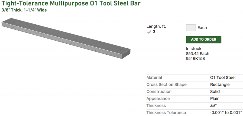
The platen is a piece of precision ground steel bar stock, and can be found at McMaster-Carr in lengths of 1.5 ft., 3 ft., and 6 ft. which is great. The bar stock isn't too badly priced. [www.mcmaster.com]
The platen needs teeth cut into it at a tooth pitch of 1mm, teeth width of 0.5mm, and a cut depth of 0.5mm.
I think the platen could easily be made at home with a wet tile saw and a jig. The jig would be a sled that places the bar stock at the proper cutting depth from the arc of the blade, and the jig will have a pin that sets the pitch of the teeth; for each cut made the previous tooth is placed over the pin in the jig.
The platen is the method of movement, the linear guide, and could also be used as the towers in a delta printer directly, making for a sweet setup.
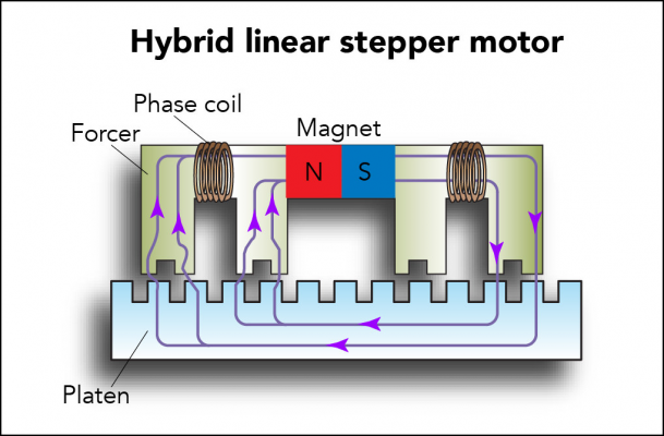
The forcer will be more complicated to make; it is essentially a transformer split in half with a permanent magnet between the two and ball bearings that ride along the platen. The force of the permanent magnet means you can use the linear stepper in either a horizontal or vertical position. The ball bearings maintain a 25 micron air gap between platen and forcer.
Someone in another thread mentioned the moving wires in the forcer and that it would be better if the electromagnets were in the platen. While this is possible, it isn't feasible or cost effective to build in a multitude of electromagnets within the length of the platen as more machining would be involved.
Everything you could ever want to know about linear stepper motor theory and design is in this publication: [issuu.com]
Edited 11 time(s). Last edit at 03/10/2018 08:26PM by klcjr89.
|
Re: Linear stepper motors March 10, 2018 05:31PM |
Admin Registered: 16 years ago Posts: 13,884 |
... look at the images in this 11 years old thread - [forums.reprap.org]
Especially on the images of the Brother type-wheel printer with the same "toothed steel barn" for positioning the print head.
Could give you some more ideas
Viktor
--------
Aufruf zum Projekt "Müll-freie Meere" - [reprap.org] -- Deutsche Facebook-Gruppe - [www.facebook.com]
Call for the project "garbage-free seas" - [reprap.org]
Especially on the images of the Brother type-wheel printer with the same "toothed steel barn" for positioning the print head.
Could give you some more ideas

Viktor
--------
Aufruf zum Projekt "Müll-freie Meere" - [reprap.org] -- Deutsche Facebook-Gruppe - [www.facebook.com]
Call for the project "garbage-free seas" - [reprap.org]
|
Re: Linear stepper motors March 10, 2018 05:42PM |
Registered: 6 years ago Posts: 207 |
Quote
VDX
... look at the images in this 11 years old thread - [forums.reprap.org]
Especially on the images of the Brother type-wheel printer with the same "toothed steel barn" for positioning the print head.
Could give you some more ideas
Yes, I saw that thread

Making the forcer will be a challenge but a 3D printed one for a prototype could work.
|
Re: Linear stepper motors March 10, 2018 06:32PM |
Registered: 6 years ago Posts: 207 |
|
Re: Linear stepper motors March 10, 2018 11:17PM |
Registered: 11 years ago Posts: 335 |
If I had to make these I'd probably try to get someone to cut the teeth in 1/8 to 1/4" plate and then laminate a few together to achieve the desired width. A laminated stator will perform just as well as a solid one. The tooth size is probably slightly too small for waterjet but its possible laser could do it. If you work in a commonly used material these processes can be fairly cheap, and you can use the same process to make the forcer as well.
Etching would also be a good DIY option but could become a PITA if you want a long bar of the stuff.
Edited 1 time(s). Last edit at 03/10/2018 11:20PM by 691175002.
Etching would also be a good DIY option but could become a PITA if you want a long bar of the stuff.
Edited 1 time(s). Last edit at 03/10/2018 11:20PM by 691175002.
|
Re: Linear stepper motors March 10, 2018 11:30PM |
Registered: 6 years ago Posts: 207 |
Doing some more digging, I found out that each step is 250 microns, aka 4 steps per mm in full step mode.
Is this too coarse for use in 3D printing on a delta printer, even if we use high microstepping such as 256?
This may kill the idea?
Edited 5 time(s). Last edit at 03/11/2018 12:37AM by klcjr89.
Is this too coarse for use in 3D printing on a delta printer, even if we use high microstepping such as 256?
This may kill the idea?

Edited 5 time(s). Last edit at 03/11/2018 12:37AM by klcjr89.
|
Re: Linear stepper motors March 11, 2018 03:32AM |
Registered: 10 years ago Posts: 14,672 |
4 full steps/mm is 64 microstep/mm at x16 microstepping, which is just a little lower than the 80 microsteps/mm @x16 that is commonly used on belt driven printers. So it looks just about high enough, provided that the linearity of microstepping is as good as it is for normal hybrid stepper motors.
Large delta printer [miscsolutions.wordpress.com], E3D tool changer, Robotdigg SCARA printer, Crane Quad and Ormerod
Disclosure: I design Duet electronics and work on RepRapFirmware, [duet3d.com].
Large delta printer [miscsolutions.wordpress.com], E3D tool changer, Robotdigg SCARA printer, Crane Quad and Ormerod
Disclosure: I design Duet electronics and work on RepRapFirmware, [duet3d.com].
|
Re: Linear stepper motors March 11, 2018 05:26AM |
Admin Registered: 16 years ago Posts: 13,884 |
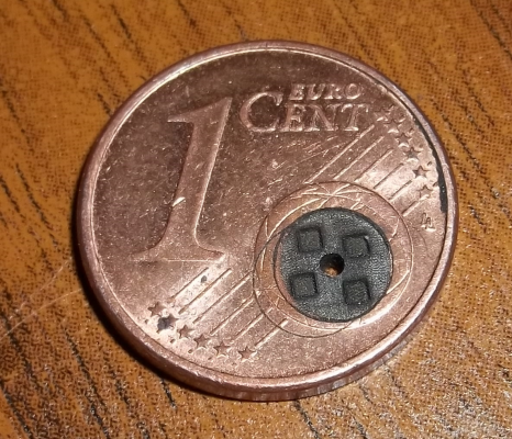
... you can make such and much finer teeth geometries with "deep laser-engraving".
I've tested with copper and iron coins:
Viktor
--------
Aufruf zum Projekt "Müll-freie Meere" - [reprap.org] -- Deutsche Facebook-Gruppe - [www.facebook.com]
Call for the project "garbage-free seas" - [reprap.org]
I've tested with copper and iron coins:
Viktor
--------
Aufruf zum Projekt "Müll-freie Meere" - [reprap.org] -- Deutsche Facebook-Gruppe - [www.facebook.com]
Call for the project "garbage-free seas" - [reprap.org]
|
Re: Linear stepper motors March 11, 2018 07:34AM |
Registered: 6 years ago Posts: 1,007 |
Funny, I proposed to use these linear motor instead of motor climbing on leadscrews to tease the OP. [forums.reprap.org]
One important thing, it has to be soft iron and tool steel is not suitable and very hard to machine !
And the accuracy that can be achieved exceed what is need in 3D printers (better than 10 micron). This technology has been used for decades. Same principle as DC42 explained. These are just flat steppers.
"A comical prototype doesn't mean a dumb idea is possible" (Thunderf00t)
|
Re: Linear stepper motors March 11, 2018 12:55PM |
Registered: 6 years ago Posts: 207 |
|
Re: Linear stepper motors March 11, 2018 10:03PM |
Registered: 6 years ago Posts: 207 |
|
Re: Linear stepper motors March 12, 2018 07:19AM |
Registered: 6 years ago Posts: 1,007 |
Quote
klcjr89
Quote
MKSA
One important thing, it has to be soft iron and tool steel is not suitable and very hard to machine !
O1 is easy to work with since it comes unhardened (annealed) with high speed steel tooling. It only becomes much hard after you oil harden it.
Once again, these rails have to be soft iron ! Like in transformers, motors, steppers etc..... !!!!
I never imagined you would machine O1 it in a harden state !
"A comical prototype doesn't mean a dumb idea is possible" (Thunderf00t)
|
Re: Linear stepper motors March 12, 2018 07:33AM |
Registered: 11 years ago Posts: 5,780 |
I have cut linear guides on several occasions and found that a cut off wheel on a grinder seems to work best, and even then, it chews up the cut-off wheel pretty quickly. Maybe you can cut regular grooves into a rail using a grinder mounted on a fixture, but I doubt it would give the required precision, and I suspect the magnetic properties of the rail are going to be a problem.
What if you just put suitably prepped iron rods on either side of a linear guide and mount the coils on the bearing block?
Edited 1 time(s). Last edit at 03/12/2018 07:36AM by the_digital_dentist.
Ultra MegaMax Dominator 3D printer: [drmrehorst.blogspot.com]
What if you just put suitably prepped iron rods on either side of a linear guide and mount the coils on the bearing block?
Edited 1 time(s). Last edit at 03/12/2018 07:36AM by the_digital_dentist.
Ultra MegaMax Dominator 3D printer: [drmrehorst.blogspot.com]
|
Re: Linear stepper motors March 12, 2018 08:29AM |
Registered: 8 years ago Posts: 5,232 |
|
Re: Linear stepper motors March 12, 2018 12:37PM |
Registered: 6 years ago Posts: 207 |
|
Re: Linear stepper motors March 12, 2018 12:53PM |
Registered: 11 years ago Posts: 335 |
You are primarily concerned with magnetic permeability, which is why soft iron or electrical steels are often used. [en.wikipedia.org]
In my limited experience its nearly impossible to buy the fancy stuff, so most hobbyists default to durabar or the usual steels.
Modifying a linear rail is a very interesting idea. I think you might have to stay away from the MG series of rails though, as they are stainless. The harder grades of stainless might hold a magnet but permeability is so low that stepper force will be very limited.
|
Re: Linear stepper motors March 12, 2018 01:03PM |
Registered: 6 years ago Posts: 207 |
Quote
691175002
You are primarily concerned with magnetic permeability, which is why soft iron or electrical steels are often used. [en.wikipedia.org]
In my limited experience its nearly impossible to buy the fancy stuff, so most hobbyists default to durabar or the usual steels.
Modifying a linear rail is a very interesting idea. I think you might have to stay away from the MG series of rails though, as they are stainless. The harder grades of stainless might hold a magnet but permeability is so low that stepper force will be very limited.
All the chiwin clones I've had in MGN series are definitely steel and not stainless. Only the Hiwin's are stainless perhaps?
|
Re: Linear stepper motors March 12, 2018 04:05PM |
Registered: 11 years ago Posts: 335 |
Quote
klcjr89
All the chiwin clones I've had in MGN series are definitely steel and not stainless. Only the Hiwin's are stainless perhaps?
The Hiwins are stainless, I'm not sure about the clones: [motioncontrolsystems.hiwin.com]
Maybe do a test run with Chinese rail; but if you are going to go through the trouble of cutting grooves I feel like you might as well use high quality rail. Misumi offers their MGN equivalent in both carbon and stainless versions. You will probably have to modify the grease seals on the blocks or they will get caught in the grooves.
|
Re: Linear stepper motors March 12, 2018 04:11PM |
Registered: 6 years ago Posts: 207 |
Quote
691175002
The Hiwins are stainless, I'm not sure about the clones: [motioncontrolsystems.hiwin.com]
Maybe do a test run with Chinese rail; but if you are going to go through the trouble of cutting grooves I feel like you might as well use high quality rail. Misumi offers their MGN equivalent in both carbon and stainless versions. You will probably have to modify the grease seals on the blocks or they will get caught in the grooves.
I have a bunch of chinese rails, and I feel that it would be better to hack those up first to see if the concept is even feasible.
The linear stepper companies fill the cut grooves with epoxy so that the air bearing model forcers can levitate, however I won't be pursuing air bearing forcers.
I'm thinking that there could be two MGN style carriages per rail, with the 3D printed forcer prototype bolted in between the two carriages, that's if it's not possible with one carriage.
Edited 1 time(s). Last edit at 03/12/2018 04:12PM by klcjr89.
|
Re: Linear stepper motors March 14, 2018 03:46PM |
Registered: 6 years ago Posts: 207 |
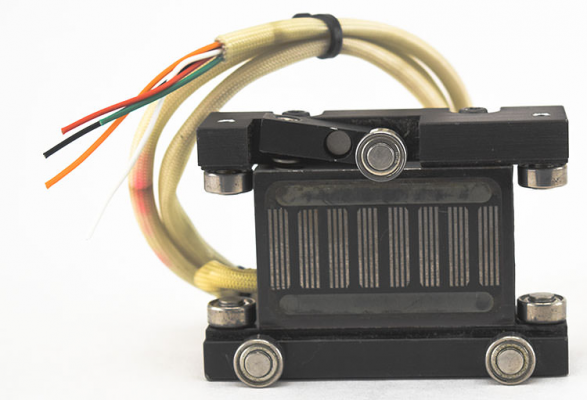
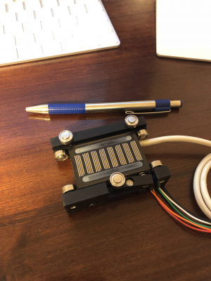
I scored the bargain of the century, and picked up a $900 forcer for $35. This is the smallest one they make, and it's going to sacrifice itself for dissection. 
Phase resistance: 2 ohms
Rated current: 1.5 amps
Inductance: 1.2mH
Force: 8.9 Newtons
Edited 6 time(s). Last edit at 03/14/2018 11:14PM by klcjr89.

Phase resistance: 2 ohms
Rated current: 1.5 amps
Inductance: 1.2mH
Force: 8.9 Newtons
Edited 6 time(s). Last edit at 03/14/2018 11:14PM by klcjr89.
|
Re: Linear stepper motors March 14, 2018 06:53PM |
Registered: 6 years ago Posts: 207 |
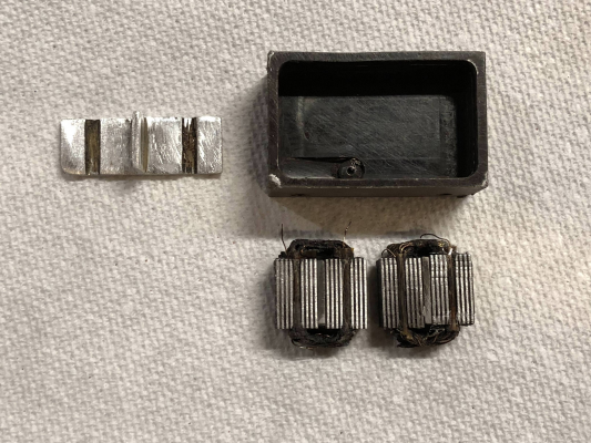
I had to use a blowtorch to dissect it, as industrial potting compound was used.
The housing is on the left, and the two phases are on the right. Will clean up the char next.
The housing is on the left, and the two phases are on the right. Will clean up the char next.
|
Re: Linear stepper motors March 14, 2018 11:04PM |
Registered: 6 years ago Posts: 207 |
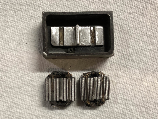
The harvest was very successful! Spent some time cleaning up the mess and learned quite alot on how these are made. Luckily the blow torch didn't destroy anything other than the permanent magnet's magnetism.
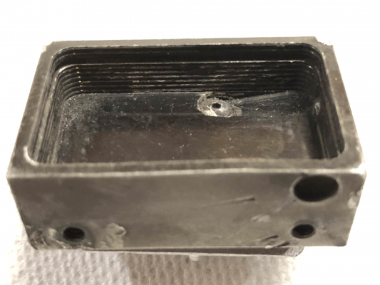
The main housing is aluminum and is grounded via a seperate wire, so that's why there were five wires. The ground wire was riveted into the housing, which you can see the rivet in the bottom of the sloped pocket milled out in the main housing.
The ridges in the walls of the main housing seem to only function as a mechanical means for the potting compound to have better mechanical adhesion. I'm guessing that the electromagnet sub-assembly is potted first, and then pressed into the main housing later, rather than pouring the potting compound directly into the main housing (although I could be wrong).
The T shaped piece is aluminum, it sits in the bottom of the main housing.
The electromagnets are made up of silicon steel laminations.
There is one permanent magnet in each phase, which sits in the middle of the coil winding and locates with the groove in the T shaped aluminum piece.
Next up will be to count the amount of laminations, find the AWG of the magnet wire, and count the number of coil turns.
Pics:
Edited 8 time(s). Last edit at 03/15/2018 01:00AM by klcjr89.
|
Re: Linear stepper motors March 15, 2018 04:18PM |
Registered: 6 years ago Posts: 207 |
I have done some more work, and have determined that the magnet wire size is 28 AWG.
There are 92 turns of wire per phase (probably 90 actually).
There are 60 laminations on each side of the phase coil, so there are 120 laminations per phase. Each lamination thickness is 0.25mm.
Now that the reverse engineering is complete, trying to figure out where to go from here?
There are 92 turns of wire per phase (probably 90 actually).
There are 60 laminations on each side of the phase coil, so there are 120 laminations per phase. Each lamination thickness is 0.25mm.
Now that the reverse engineering is complete, trying to figure out where to go from here?

|
Re: Linear stepper motors March 15, 2018 05:59PM |
Registered: 11 years ago Posts: 335 |
The most difficult part of the project will likely be finding appropriate rail and cutting grooves in it. I think you might end up needing one of the back-mounting variations (ex: [www.automation-overstock.com] ) because hole counterbores in standard rail might cause issues.
I'd probably try to quickly rebuild the existing forcer with new wire and magnets so you have something to test the grooved rail against. No need to pot it in epoxy, just print a housing that maybe slides against the side of the rail so it is easy to test.
Building a forcer is very straightforward, but I think you will have to pay someone to laser/waterjet the laminations. Luckily you just want a ton of the same shape, so if you tab them in a sheet (and clip them out yourself later) you should be able to get a really good deal. You could even cut them in 0.5 or 1mm sheet since eddy currents shouldn't be as much of an issue at 3d printer speeds.
|
Re: Linear stepper motors March 15, 2018 06:08PM |
Registered: 6 years ago Posts: 207 |
Quote
691175002
The most difficult part of the project will likely be finding appropriate rail and cutting grooves in it. I think you might end up needing one of the back-mounting variations (ex: [www.automation-overstock.com] ) because hole counterbores in standard rail might cause issues.
I noticed there are commercial forcer platens with counterbored holes in the top side, so it probably doesn't effect it too much.
How many Newtons of force are required for 3D printing? The one I tore apart was 8.9 Newtons.
Edited 1 time(s). Last edit at 03/15/2018 06:08PM by klcjr89.
|
Re: Linear stepper motors March 15, 2018 06:57PM |
Registered: 10 years ago Posts: 14,672 |
Quote
klcjr89
How many Newtons of force are required for 3D printing? The one I tore apart was 8.9 Newtons.
That's quote low. We typically use stepper motor with 25 to 50Ncm of torque at rated current. If you put a 20 tooth GT2 pulley on one, the effective pulley radius is about 6.4mm, which means the holding force on the belt at rated current is about 40N to 80N.
Large delta printer [miscsolutions.wordpress.com], E3D tool changer, Robotdigg SCARA printer, Crane Quad and Ormerod
Disclosure: I design Duet electronics and work on RepRapFirmware, [duet3d.com].
|
Re: Linear stepper motors March 15, 2018 06:59PM |
Registered: 6 years ago Posts: 207 |
Quote
dc42
Quote
klcjr89
How many Newtons of force are required for 3D printing? The one I tore apart was 8.9 Newtons.
That's quote low. We typically use stepper motor with 25 to 50Ncm of torque at rated current. If you put a 20 tooth GT2 pulley on one, the effective pulley radius is about 6.4mm, which means the holding force on the belt at rated current is about 40N to 80N.
Are you sure that much is "needed" though for printing? And the company doesn't specify Ncm, only Newtons for the forcer.
Edited 1 time(s). Last edit at 03/15/2018 06:59PM by klcjr89.
|
Re: Linear stepper motors March 15, 2018 07:19PM |
Registered: 6 years ago Posts: 207 |
@dc42, what's your take on the following specs and performance curves to see if the idea should be abandoned or not? Thanks!
Edited 3 time(s). Last edit at 03/15/2018 07:27PM by klcjr89.
Edited 3 time(s). Last edit at 03/15/2018 07:27PM by klcjr89.
|
Re: Linear stepper motors March 16, 2018 03:40AM |
Registered: 8 years ago Posts: 5,232 |
|
Re: Linear stepper motors March 16, 2018 03:52AM |
Registered: 10 years ago Posts: 14,672 |
To move the head of a 3D printer, you don't need a lot of force. For example, if the target acceleration is 2500mm/sec^2 (2.5m/sec^2) and the mass of the print head is 0.2kg then you need only 0.2 * 2.5 = 0.5N to move it. However, using microstepping reduces the holding torque by a factor of 1/sqrt(2) compared to always having both phases energised at full current. If we want precise positioning with 1/16 microsteps then we need around 10x more holding torque. Also we don't normally run motors at their full rated current because that makes them very hot, so add another 20%. All this means that our 0.5N required movement force translates to about 10N holding force assuming a low-friction system.
So the 0604, 1302 and 1304 linear motors look suitable for moving the carriages of a delta printer, or the print head along the X axis in a Cartesian printer with a Bowden or remote drive extruder. Even the 0602 motor may be sufficient for a small delta. Moving the bed or gantry of a Cartesian printer requires more force because of the additional moving mass.
So yes, it is worth pursuing.
Use laminations to make the iron parts to avoid high losses when moving at speed, just as rotary stepper motors do.
Large delta printer [miscsolutions.wordpress.com], E3D tool changer, Robotdigg SCARA printer, Crane Quad and Ormerod
Disclosure: I design Duet electronics and work on RepRapFirmware, [duet3d.com].
Sorry, only registered users may post in this forum.
