Tripteron Implementation
Posted by Apsu
|
Re: Tripteron Implementation November 08, 2016 01:35AM |
Registered: 7 years ago Posts: 143 |
|
Re: Tripteron Implementation November 08, 2016 08:05AM |
Registered: 7 years ago Posts: 1 |
Very intersting!
You could theoretically even go with the stepper gear wheel driving directly on a rack, thus removing belts alltogether.
And if I understand this correctly, on every axis the force on the arm is only along that axis, so if you wanted you could make the arms slimmer and wider. because it only experiences strain parallel to the wide surface?
|
Re: Tripteron Implementation November 08, 2016 08:50AM |
Registered: 9 years ago Posts: 189 |
|
Re: Tripteron Implementation November 08, 2016 11:03AM |
Registered: 7 years ago Posts: 143 |
Quote
mavu
Very intersting!
You could theoretically even go with the stepper gear wheel driving directly on a rack, thus removing belts alltogether.
Yep. This can be driven any way you choose, any combination of belts, gears, water and sailboats. But belts certainly aren't Bad, there's tradeoffs, as with everything.
Quote
And if I understand this correctly, on every axis the force on the arm is only along that axis, so if you wanted you could make the arms slimmer and wider. because it only experiences strain parallel to the wide surface?
Yes and no. You still need enough material to actually provide stiff joint mounting. Lots of balancing in terms of materials, geometry, cross section and so forth.
|
Re: Tripteron Implementation November 08, 2016 03:47PM |
Registered: 7 years ago Posts: 143 |
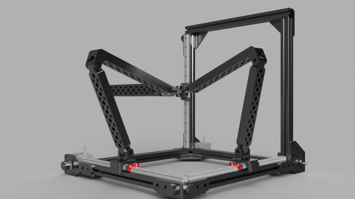
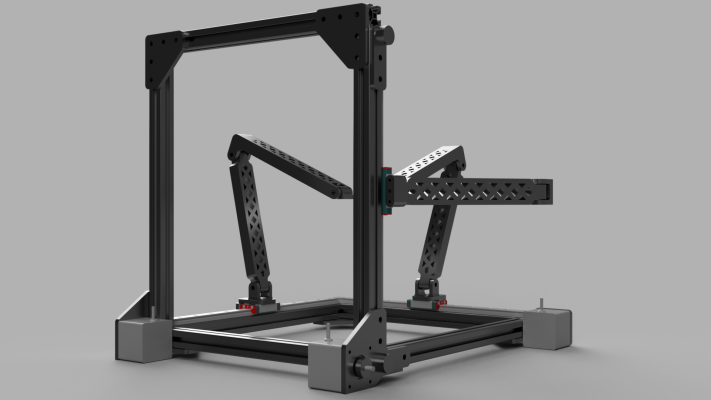
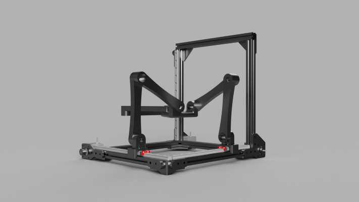
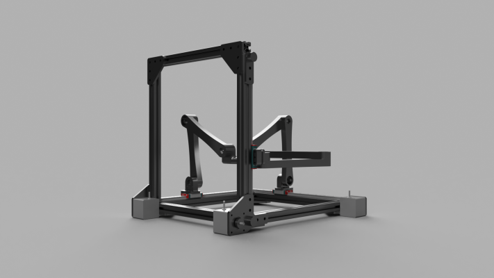
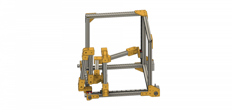
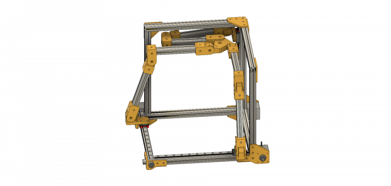
Ok, got the bracketing figured out, motors are all the same distance below the frame, active belt paths are all linear, just needed one extra idler on the Z bracket. Made some bigger and cleaner renderings to illustrate the layout.
And yes, I realize I have some of the motor pinions slightly askew and the Y belt clamp spacer is shifted. Details, have to get back to work, etc ;P
And yes, I realize I have some of the motor pinions slightly askew and the Y belt clamp spacer is shifted. Details, have to get back to work, etc ;P
|
Re: Tripteron Implementation November 09, 2016 06:38AM |
Registered: 8 years ago Posts: 5,232 |
|
Re: Tripteron Implementation November 09, 2016 10:48AM |
Registered: 8 years ago Posts: 1,671 |
|
Re: Tripteron Implementation November 09, 2016 01:31PM |
Registered: 7 years ago Posts: 143 |
Alright, got a fun update. Got everything put together minus the extra Z bracing (still waiting on extrusion delivery!). I lubed up all the joints, tightened everything down, put a little weight/indicator on the effector, and ran some gcode slow at low accel to give it the best chance of good behavior.
YouTube Link
Short video of 40mm/s @ 200mm/s^2 accel. There's a small hitch in the video near the beginning as I'm switching screens on my laptop. Even though I buffered the webcam capture, this laptop has an integrated GPU so the encoding software still hiccupped slightly. That wasn't the arms binding Rest of the video is a good indication of how smooth the motion is with these settings.
Higher settings work too, though we start getting into slight mechanical backlash at really high accel on sharp changes. I'm going to redesign the forked arms and shoulders to have bearings in them as well with wider bosses, so I'll have joint arrangements like this:
bolt - washer - fork [boss - bearing] - spacer - arm [bearing - boss - bearing] - spacer - fork [bearing - boss] - washer - nylock nut
This should improve the joint stability even further by increasing bolt length, radial surface contact and not relying on the fork M5 holes/washers/tension to keep them in place. I should be able to reduce the joint tension while gaining stiffness, thus reducing bearing friction and removing backlash sources further. Pretty much a win all around.
Preloading the joints by adding some mass to the effector (and thus also some inertia) seems to improve the behavior as well, so it definitely seems like the joints are the current limitation, and that's easy to continue improving on.
tl;dr though, it works! It's behaving completely reasonably for this stage in the prototyping process. YAY SCIENCE!
EDIT: Here's a fun video of it moving way too fast, where some of the backlash is visible YouTube Link. This is 300mm/s @ 5000mm/s^2 accel. And yes, that's a squeaky pulley. I need to replace the spacers and shim them up a few mm and lube them, anyway. But there it is. The gcode is for a bag-clip model with tiny teeth, so not all of that is backlash, but some of it is. Certainly makes it easier to see at this speed/accel
Edited 1 time(s). Last edit at 11/09/2016 02:14PM by Apsu.
YouTube Link
Short video of 40mm/s @ 200mm/s^2 accel. There's a small hitch in the video near the beginning as I'm switching screens on my laptop. Even though I buffered the webcam capture, this laptop has an integrated GPU so the encoding software still hiccupped slightly. That wasn't the arms binding
 Rest of the video is a good indication of how smooth the motion is with these settings.
Higher settings work too, though we start getting into slight mechanical backlash at really high accel on sharp changes. I'm going to redesign the forked arms and shoulders to have bearings in them as well with wider bosses, so I'll have joint arrangements like this:
bolt - washer - fork [boss - bearing] - spacer - arm [bearing - boss - bearing] - spacer - fork [bearing - boss] - washer - nylock nut
This should improve the joint stability even further by increasing bolt length, radial surface contact and not relying on the fork M5 holes/washers/tension to keep them in place. I should be able to reduce the joint tension while gaining stiffness, thus reducing bearing friction and removing backlash sources further. Pretty much a win all around.
Preloading the joints by adding some mass to the effector (and thus also some inertia) seems to improve the behavior as well, so it definitely seems like the joints are the current limitation, and that's easy to continue improving on.
tl;dr though, it works! It's behaving completely reasonably for this stage in the prototyping process. YAY SCIENCE!

EDIT: Here's a fun video of it moving way too fast, where some of the backlash is visible YouTube Link. This is 300mm/s @ 5000mm/s^2 accel. And yes, that's a squeaky pulley. I need to replace the spacers and shim them up a few mm and lube them, anyway. But there it is. The gcode is for a bag-clip model with tiny teeth, so not all of that is backlash, but some of it is. Certainly makes it easier to see at this speed/accel

Edited 1 time(s). Last edit at 11/09/2016 02:14PM by Apsu.
|
Re: Tripteron Implementation November 10, 2016 03:46PM |
Registered: 7 years ago Posts: 143 |
Bit of an update.
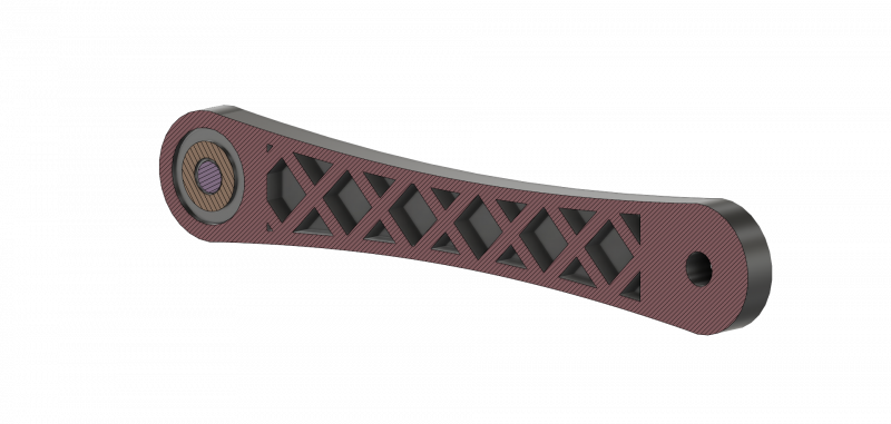
I decided to investigate using M8 hardware and 608 bearings since I had some 608VVs with rubber seals on hand and a few M8 bolt/washer/locknut pieces. I came up with an arm design and bearing mounting system that actually works pretty well. Here's a cross-section view of one arm. Part of the bearing/bolt setup is visible on the left, if you're confused by what's there.
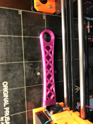
View of the print in progress so you can see the internal latticework and spacing
And a couple completed prints (0.25mm layers, 40% triangle infill, 4 perimeters so internal lattice is all solid perim) with a joint setup between them
This kind of printing and internal structure results in an extremely strong, yet pretty light (50g per 150mm joint-to-joint long) part. So that just leaves the joint design and performance considerations. The joint structure is:
M8 hex-cap 35mm -> M8 flat washer -> Arm [608VV bearing -> M8 flat washer -> 608VV bearing] -> M8 flat washer -> Arm [M8 nylock nut]
I'm planning to replace the washer between the bearings with either a printed boss or try expanding some M12 split-ring/lock washers, so that the bearing casings/outer rings are supported inside the arm, rather than the inner ring/journals touching via the M8 washer. The reason for this is to accomplish a very stiff preload to prevent the bearings from experiencing any play or wiggle room. Details can be found here. The setup I'm going for is a solid back-to-back preload, M8 washers pushing on journals from the outside and a boss/M12 ring separating the casings from the inside, then applying static tension via the the locknut.
Even without the proper preloading, the bearing play is extremely minimal and the joint is SOLID yet spins freely where it should.
I'll update later when I have a chance to figure out the internal spacing choice (boss or split-ring) and can do some testing on it. I have all the hardware to complete every joint and rebuild the Tripteron arm assembly using this new design, so it shouldn't take long to give it a real empirical test.
Edited 1 time(s). Last edit at 11/10/2016 03:47PM by Apsu.
|
Re: Tripteron Implementation November 11, 2016 01:19AM |
Registered: 7 years ago Posts: 143 |
Got the rest of the basic CAD done to print and assemble everything.
Renderings from front and back:
Effector mount is closer to correct now, though I think I'll switch the shoulder on the X (front) axis so the effector attachment is on the left instead of right (towards Y rail), helping to balance left/right extremes due to X rail positioning.
I'm not sure if this approach is the "best" way to do it, but the joint system is much more stiff, much much simpler to assemble/adjust and the preload can be extremely tight without significantly impacting joint mobility. So assuming the arm weight increase (just shy of 200g now) isn't "too much", I can't see how it won't be a significant improvement over the previous iteration, where preloading the joints and the tiny bearings was extremely difficult.
Parts are printing overnight so I'll likely have this assembled and moving at least some in the morning. We'll see what comes out of it!
|
Re: Tripteron Implementation November 11, 2016 11:28AM |
Registered: 7 years ago Posts: 143 |
Decided to try adding M8/608 to my previous arm design, since the lattice orientation is more correct for the needed reinforcement, and looks badass (I think  ).
).
Here's an animation showing the arm links, joint, hardware and exploded view of how the joint is assembled.
YouTube Link
 ).
).Here's an animation showing the arm links, joint, hardware and exploded view of how the joint is assembled.
YouTube Link
|
Re: Tripteron Implementation November 13, 2016 03:52PM |
Registered: 7 years ago Posts: 143 |
Update time
After extensive thinking, modeling, simulation and empirical testing, it's clear that the un-bossed bearing mounts are insufficient to maintain rigidity once the arms get strong enough. Instead, the bearing orientation becomes the weak point, and they tilt inside the 22.2mm cutout. I worked really hard to figure out how to secure, boss, and preload the bearings without significantly extending the joint width and bolt length, and eventually concluded that the only correct solution is to use a thrust bearing.
Here's the current joint design, animated and exploded into parts:
YouTube Link
Each arm link (white rings) has a slot for the 608 bearing, a 16x22 spacer (optional) to stabilize the casing against the boss, the boss itself, then a 19x1 slot on the inner face for one plate of the 8x19x3.5 thrust bearing. The thrust plates being inset helps retain and orient them, as well as reducing the spacing between links. The same setup is used on the other link, in reverse. An M8 bolt is inserted through the assembly, with a standard M8 washer between bolt head/locknut and the 608 bearing journals. This allows the bolt to "float" with the journals, purely riding the preloaded balls in the bearings.
The result is that we get a true back-to-back solid preload on the 608s, with the thrust bearing acting as part of the preload structure, itself being preloaded for smooth operation. The bolt tension is easily adjustable and all parts are easily assembled.
The 608 casing spacers are optional because the printed boss is sufficient, I just happen to have some appropriate spacers I ordered, so I may or may not use them. Depends on how thick of a boss I end up wanting to print. But they're definitely optional within the design constraints and material strengths -- all that matters is that the journals facing each other don't touch the boss material, same with the bolt. Both must "float" freely between the links, bolt passing through the thrust bearing.
|
Re: Tripteron Implementation November 14, 2016 02:11PM |
Registered: 8 years ago Posts: 5,232 |
Now that you've "discovered" the thrust bearing advantage, do you still need the extra beefy 608 bearings? Initially I thought, needle bearings would be useful. What do you think?
There is a saying in german: There is never enough time to do things right, but then there is always time to do it again....
There is a saying in german: There is never enough time to do things right, but then there is always time to do it again....
|
Re: Tripteron Implementation November 14, 2016 02:23PM |
Registered: 7 years ago Posts: 143 |
Quote
o_lampe
Now that you've "discovered" the thrust bearing advantage, do you still need the extra beefy 608 bearings? Initially I thought, needle bearings would be useful. What do you think?
There is a saying in german: There is never enough time to do things right, but then there is always time to do it again....
The 608s are way over-spec'd for the loads involved, yes, as are 8mm axles. However... smaller bearing outer diameters mean less orientation stability and less plastic to house them, all of which results in less overall rigidity. In addition, radial bearings require preloading for proper operation, and getting appropriate sized spacers for smaller bearing systems is actually quite difficult. Moving to 608 wasn't on a whim, it's the result of a lot of competing factors coming together.
This would be a *very* different proposition if everything was metal. And to be honest I've considered using 1515 extrusion for arm links with machined brackets for joint mounting. Everything could be smaller and with tight clearance fit, basically perfect performance at a light weight. But that would require custom parts that aren't printable, and that's a little counter to the direction I'm trying to go in

Not to say I won't go down that road too just to see what kind of machine I can build. I mean... I'm kind of veering that way a little already because I now have thrust bearings (not as common) and getting some M6 8x30mm shoulder bolts to improve axle performance soon (not expensive but also not common in hobby assemblies). But for the most part I find the plastic particularly interesting and challenging. After all, I'm having fun here

|
Re: Tripteron Implementation November 15, 2016 02:33AM |
Registered: 8 years ago Posts: 5,232 |
|
Re: Tripteron Implementation November 15, 2016 09:55PM |
Registered: 7 years ago Posts: 143 |
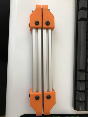
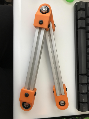
Ok, I decided to get my extra 2020 chop-sawed into appropriate lengths and try 'em with printed brackets. I just wan't getting the performance I wanted out of the printed arms no matter what I tried or how solid they were sliced/printed.
Here's a short video of the idea
YouTube Link
Have to say... this is *by far* the strongest thing I've assembled yet, and I just tweaked the model to add even more reinforcement in the back of the joint cavity. I bolted it to my existing shoulder that is just a hole + captive nut in the PLA, and it was tilting the bolt, zero deflection in the Aluminum, bearings or bracket. This is incredibly stiff, and with a pair on each end, arm links should weigh in around 155-160g, which is about where all the other link designs were on weight.
Printing a few more and a shoulder so I can test two links at extension and the full joint system... but, obviously, metal is orders of magnitude stronger here. The stubby, triple-bolted bracket seems to be ideal as well. So I think this problem may in fact be solved, without using custom metal parts, still. After all, you can order t-slotted extrusions cut to any length you need, so I'm not worried about that at all.
After testing, assuming it goes well (and it sure looks like it will), I'll print the rest of the set and get an effector hooked up and **ROUND TWO** can start moving!
|
Re: Tripteron Implementation November 16, 2016 02:38AM |
Registered: 8 years ago Posts: 5,232 |
|
Re: Tripteron Implementation November 16, 2016 11:21AM |
Registered: 7 years ago Posts: 143 |
Quote
o_lampe
Yeah, 2020 extrusion will make it for sure!
Don't want to be nagging, but I still think carbon rods are even better and also widely available.
Sure, I've considered CF rods, but I'm not sure of an easy way to mount joints to reasonably-sized rods, or cut them to the sizes I need if I can't find some that are already close. With a Delta, it's much easier because there's not nearly as much lateral stability to engineer the ball-joints around, it's all about the stiffness along the length, which CF is perfect for. The parallel linkage arrangement provides the lateral stability mostly through length stiffness combining in the pair, rather than the joint itself.
Still, there's other potential ways to do it, like printing arms with channels to insert CF rods into. It's not a bad idea at all, but we'll see how far I can get on the 2020 path since I've got everything I need and these brackets seem to be working great.
Here's a look at where I am for one arm. The first pass joint is the non-filleted one, the others are the more reinforced/smoothed ones I'm printing more of now

|
Re: Tripteron Implementation November 18, 2016 10:01AM |
Registered: 7 years ago Posts: 143 |
Big update!
I built the entire assembly using the above joint design, and sadly it seems that the thrust bearings like to 'swim' in their plastic cutouts just a little bit, which kind of defeats the whole purpose lol! There are some fixes but they push the offset link pattern even farther apart, and really it just was starting to feel unwieldy.
I had an idea to try 2020 + coplanar/inline joints, and I decided to focus on constructing it with the principle of plastic being compressed between metal, rather than metal compressed between plastic (like the thrust bearing).
Here's a video of the joint design: YouTube Link
EDIT: YouTube Link Made a bit better video showing off the components and screw holes, plus using the proper shoulder bolt model.
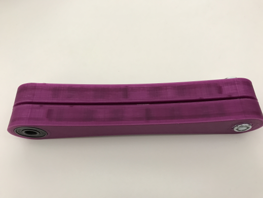
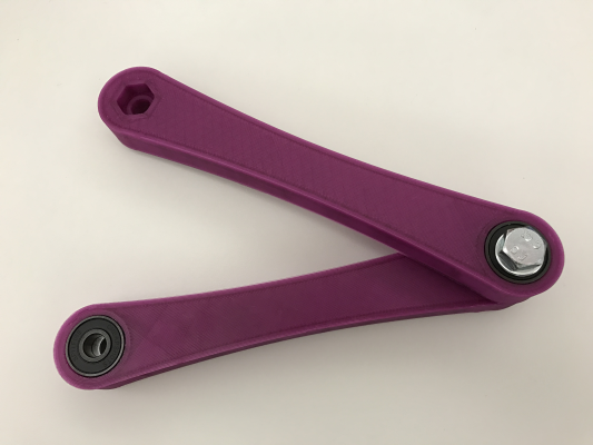
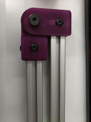
And here's some quick photos (sorry for poor quality, dim room in the morning):
The constructed joint could use an M6 washer under the nylock nut since the shoulder bolt's threading ends a little before the fork surface, so there's a tiny amount of play there, but besides that I can't flex this in my hands or clamped down at appropriate loads. There's no bounce whatsoever!
I should probably think about bushings or inserts for the forks so it's not metal on plastic, but my tolerances are very very tight in the holes that I can actually print, so I'm going to run with it for now. Very excited, seems like the design here is finally solved well enough to proceed
Edited 1 time(s). Last edit at 11/18/2016 10:23AM by Apsu.
I built the entire assembly using the above joint design, and sadly it seems that the thrust bearings like to 'swim' in their plastic cutouts just a little bit, which kind of defeats the whole purpose lol! There are some fixes but they push the offset link pattern even farther apart, and really it just was starting to feel unwieldy.
I had an idea to try 2020 + coplanar/inline joints, and I decided to focus on constructing it with the principle of plastic being compressed between metal, rather than metal compressed between plastic (like the thrust bearing).
Here's a video of the joint design: YouTube Link
EDIT: YouTube Link Made a bit better video showing off the components and screw holes, plus using the proper shoulder bolt model.
And here's some quick photos (sorry for poor quality, dim room in the morning):
The constructed joint could use an M6 washer under the nylock nut since the shoulder bolt's threading ends a little before the fork surface, so there's a tiny amount of play there, but besides that I can't flex this in my hands or clamped down at appropriate loads. There's no bounce whatsoever!
I should probably think about bushings or inserts for the forks so it's not metal on plastic, but my tolerances are very very tight in the holes that I can actually print, so I'm going to run with it for now. Very excited, seems like the design here is finally solved well enough to proceed

Edited 1 time(s). Last edit at 11/18/2016 10:23AM by Apsu.
|
Re: Tripteron Implementation November 18, 2016 01:34PM |
Registered: 8 years ago Posts: 5,232 |
|
Re: Tripteron Implementation November 18, 2016 06:02PM |
Registered: 7 years ago Posts: 143 |
Alright, I finished up the bulk of the remaining CAD and assembled it for some motion testing.
Here's a video of manual manipulation, looks like it'll work well enough to proceed!
YouTube Link
Here's a video of manual manipulation, looks like it'll work well enough to proceed!
YouTube Link
|
Re: Tripteron Implementation November 18, 2016 08:10PM |
Registered: 7 years ago Posts: 143 |
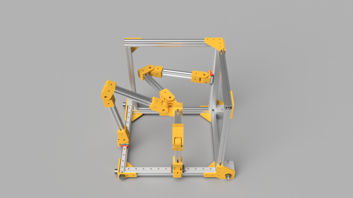
Added a couple more frame pieces and framing brackets, more like I originally intended to do. Here's a few 1080p renders to illustrate
|
Re: Tripteron Implementation November 19, 2016 08:30AM |
Registered: 8 years ago Posts: 5,232 |
|
Re: Tripteron Implementation November 19, 2016 06:03PM |
Registered: 7 years ago Posts: 143 |
Quote
o_lampe
I love the looks of it, but maybe the center platform needs an redesign? It seems to be pretty tight to mount a hotend.
Looked that way, but that was a 22mm cutout for a 608 bearing. When cut down to 12mm (J-Head groove mount diameter) there's tons of room.
In fact, I've been redesigning the effector/platform a fair bit. I made a ThingiVerse page for the project, so STLs are more easily viewed and shared. There's also up-to-date renders there.
The link is here.
|
Re: Tripteron Implementation November 20, 2016 03:30PM |
Registered: 7 years ago Posts: 143 |
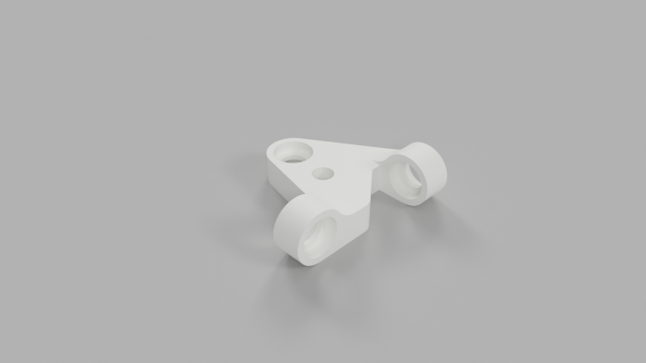
Small update, pic and turntable of latest effector design. And no, the center circle is not misaligned  It's equidistant from each axis using a particular method. Might change to a different one, we'll see.
YouTube Link
 It's equidistant from each axis using a particular method. Might change to a different one, we'll see.
YouTube Link
|
Re: Tripteron Implementation November 21, 2016 08:06PM |
Registered: 7 years ago Posts: 143 |
|
Re: Tripteron Implementation November 23, 2016 10:25PM |
Registered: 7 years ago Posts: 143 |
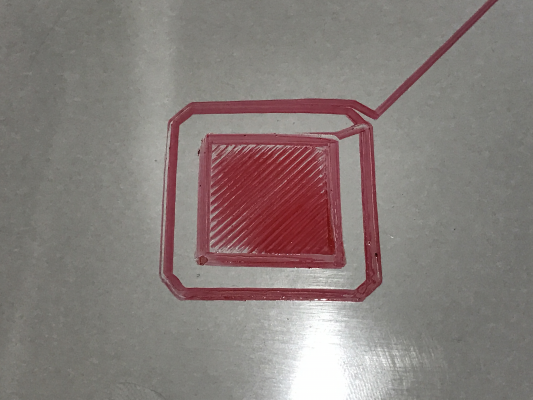
Huzzah! Looks like we're on the right track. I made it draw on a non-flat board on a non-float box on a squishy table cover, using a dry-erase marker, and yet it did a decent enough job I think I'm ready to move onto pushing plastic.
Here's a video:
YouTube Link
And the result itself:
Obviously these are not ideal conditions, and it doesn't tell me exactly what a print would look like, and there are Several things I know need to be improved (like the Z tower reinforcements)...
But that's all fine, because it seems the basic behavior is working! And with enough accuracy I don't think I need any major redesigns, so it's time to move on to actual printing and refinement
I've got some parts coming that should allow me to try printing by the weekend, so I'll update as I go.
Here's a video:
YouTube Link
And the result itself:
Obviously these are not ideal conditions, and it doesn't tell me exactly what a print would look like, and there are Several things I know need to be improved (like the Z tower reinforcements)...
But that's all fine, because it seems the basic behavior is working! And with enough accuracy I don't think I need any major redesigns, so it's time to move on to actual printing and refinement

I've got some parts coming that should allow me to try printing by the weekend, so I'll update as I go.
|
Re: Tripteron Implementation November 24, 2016 03:45AM |
Registered: 8 years ago Posts: 5,232 |
Awesome!
That looks better than the first layer of my delta ATM
BTW: I linked your Tripteron thread to this vacuum bed one, because they would be a perfect match. Maybe I can lure you into building a conveyor belt bed

Edited 2 time(s). Last edit at 11/24/2016 03:48AM by o_lampe.
That looks better than the first layer of my delta ATM

BTW: I linked your Tripteron thread to this vacuum bed one, because they would be a perfect match. Maybe I can lure you into building a conveyor belt bed

Edited 2 time(s). Last edit at 11/24/2016 03:48AM by o_lampe.
|
Re: Tripteron Implementation November 24, 2016 01:28PM |
Registered: 7 years ago Posts: 143 |
Quote
o_lampe
Awesome!
That looks better than the first layer of my delta ATM
BTW: I linked your Tripteron thread to this vacuum bed one, because they would be a perfect match. Maybe I can lure you into building a conveyor belt bed
haha. I managed to get in touch with Nicholas Seward the other day to talk about my Tripteron, and we were talking about the fact this design could actually print on a table-top, by rearranging the elbow joints so the effector hangs down lower. So that makes me think that maybe it doesn't have to be a table top, but rather Could be a plate that comes up from the bottom.
Then you talking about a conveyor system makes me wonder.... maybe the entire printer could sit on top of a lower box... with some kind of bed mechanism like a Sarrus linkage or Stewart platform (hexapod), or even scissor-lift. Just something that can lift strajight up/down, in order to push a build plate up to the effector for printing, without having to be accurate enough to raise/lower *during* printing, then lower it for removal/conveying to a holding area.
Would be pretty complicated, but the individual parts could be very robust and "easy" to do a good job with.
|
Re: Tripteron Implementation November 24, 2016 02:29PM |
Registered: 7 years ago Posts: 143 |
Small update, decided to try moving the shoulder joints out a bit more to increase the build volume and give the wrists a bit more breathing room. Looks like it'll work and is an easy tweak/print!
I like how relatively easy it is to hack on this platform
I like how relatively easy it is to hack on this platform

Sorry, only registered users may post in this forum.

