PC Flight Simulator controls
Posted by RepRot
|
PC Flight Simulator controls October 31, 2018 06:20PM |
Registered: 14 years ago Posts: 128 |
Having learnt a LOT with designing and building my versions of a Mendel and a CoreXY 3D printers I decided that I would have a go at designing and building a set of PC Flight Simulator Controls.
Having learnt to fly Cessna 152's and 172's a few years back, I wanted a set of controls based on the Cessna 172 design and I wanted them to have a more realistic look and feel, however I didn’t want a set of controls that would take over my computer desk area like a cockpit.
After a lot of brain rattling, design and construction time, I came up with a design that consists of a Flight Simulator Control Console and a Flight Simulator Control Foot Unit.
Flight Simulator Control Console:
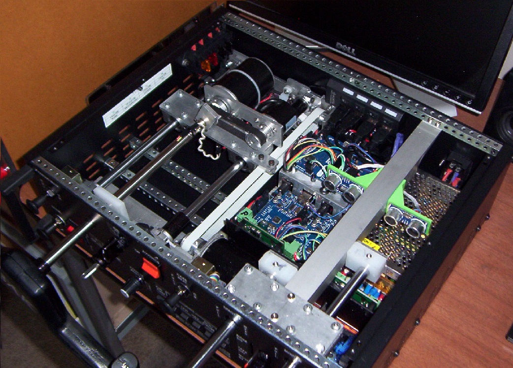
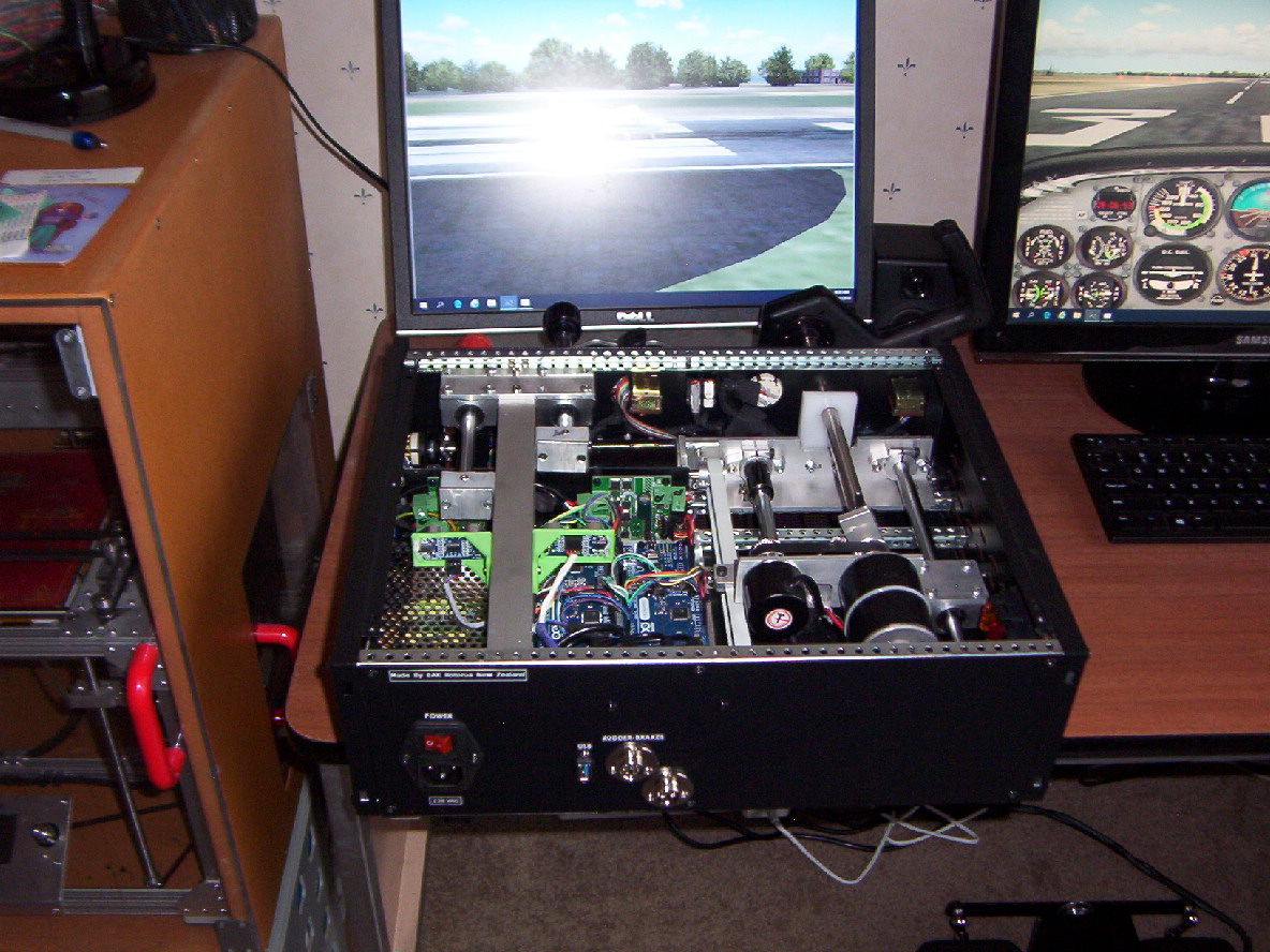
The console unit consists of a 19” rack cabinet ( U3). I didn’t use the front 19” panel due to the thickness of the aluminium. This gave me a metal box 420mm x 127mm 335 WxHxD. I kept the rack handles as it makes it easier to move about.
On the front of the console I have the main flight control handle for the aileron and elevator. This was 3D printed in 5 parts and screwed together using 2.5 mm diameter screws. Within the handle are 2 tactile SPST switches with resistors providing a 2 wire connection for an analog reading to determine which of the two switch’s is pressed.
The flight control handle is attached via a flange to a 12mm hollow stainless steel shaft and this is connected to a DC 12 volt motor which can apply rotation torque pressure. Also attached to the DC motor is a GT2 pulley and this is connected via a belt to an optical rotary encoder for aileron movement readings. The rotary encoder is a 600 pulse per revolution – 2 phase. Being two phase, this encoder can give 2400 pulses per revolution although it can only rotate 213 degrees giving 1420 encoder pulses.
The DC motor and optical rotary encoder are mounted on an aluminium bracket that is attached to two 12mm linear bearings which allows the control handle to be moved back and forth for elevator control.
Attached to this assembly there is a GT2 belt that connects onto another DC motor and optical encoder to provide torque and elevator movement readings. This gives a full elevator movement of approx 130mm – 4978 encoder pulses .
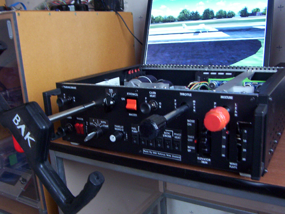
Across the front of the console are a number of switches which are laid out similar to the Cessna 172 aircraft. The rotary switches are 12 position types that can be limited to a set number of switch positions. These are used for: Fuel tank selection, Flaps position, Ignition/Magneto, Panel/Radio light dimmer.
- The Ignition/Magneto switch has been modified by using a soldering iron to change the internal detent to make it spring back from the start position. A custom made knob was made to look like a key in a lock.
- The Master Alt/Batt switch is a dual 1 pole switch which has been modified by fitting a small steel shaft to make it operate like the Cessna switch. (There are only 3 setting that can happen with this switch)
The panel/radio light dimmer switch while it is wired its not currently being used. It is reserved for future use if an instrument panel is used (Can provide a digital I/O or PWM signal if required for external light dimming).
Other switches are used for: Aircraft Lights, Pivot heat, Fuel pump, Carb heat, Parking brake, Primer.
The primer switch is a toggle type and was modified to not lock on.
On the front panel there is an elevator trim wheel, this was 3d printed and it has been fitted onto a mechanical rotary encoder. It can continuously rotate – no mechanical stop position.
Also there is a throttle and mixture sliding controls, the knobs were 3D printed and are attached to a 12 mm shaft that slides though a linear bearing. On the rear of the 12mm shaft there is a square block of Teflon which has been drilled out and a spring and round rubber piece fitted (tap seal) , this arrangement stops the knobs rotating and provides some resistant when sliding the control. On the rear of each of the square Teflon blocks there is a metal plate. I am using acoustic sensors to determine throttle and mixture position and the metal plate allows a good echo.
The acoustic sensors mounting supports were 3D printed.
On the front panel there are two indicator levers for displaying Flap position and Elevator trim. These are driven from RC servo motors.
On the rear of the console there is a mains power socket (230VAC) with a mains power On/Off switch that also includes a mains power fuse.
After the mains power switch, power is connected to an 8 amp 12volt DC power supply. The power supply output (12 volt DC) is connected to a fuse block and then is connected to four Arduino processors as well as two dual H-bridge driver PCB’s.
The two dual H-bridge driver’s supply DC power to the aileron, elevator and rudder DC torque motors.
(Only half of the second H-bridge circuit is used).
There are two connectors on the rear panel, these are for the output for the foot control unit rudder DC torque motor power, and logic data signals.
There is a USB female to female connector on the rear panel. I use a male to male USB cable from the PC.
Connected to the USB female connector is a 4 port switched hub. For normal use all the USB switches are off. With the flight simulator mains power off, the PC doesn’t see any USB devices. Only when the
flight simulator mains power is turned on will the PC see the USB devices.
This setup makes it easy when loading programs to any of the four Arduino’s. With the flight simulator mains power off, I can just turn on the switch on the Hub for the Arduino I wish to program.
With having multiple same types Arduino’s connected to a PC, it’s normally hard to determine which PC port is connected to which Arduino when they are the same name type.
Flight Simulator Control Foot Unit:
This is an original design… took a lot of brain rattling to come up with this…
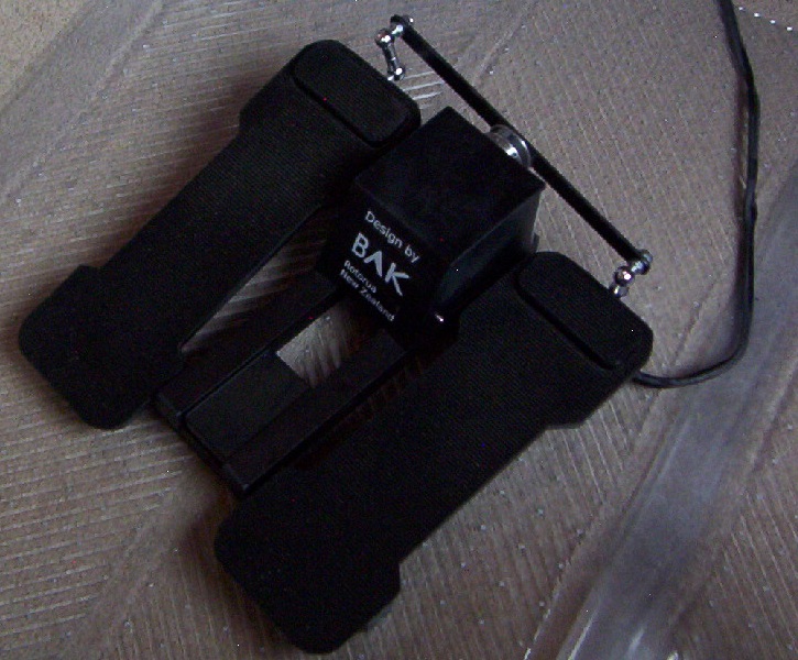
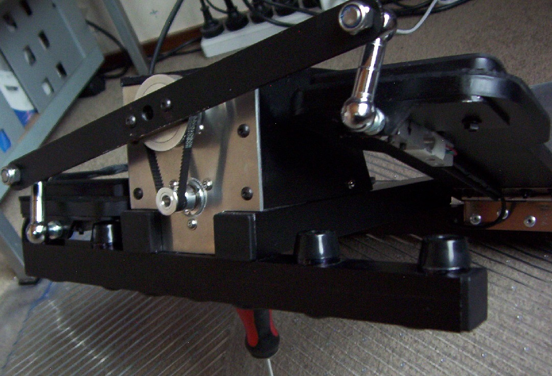
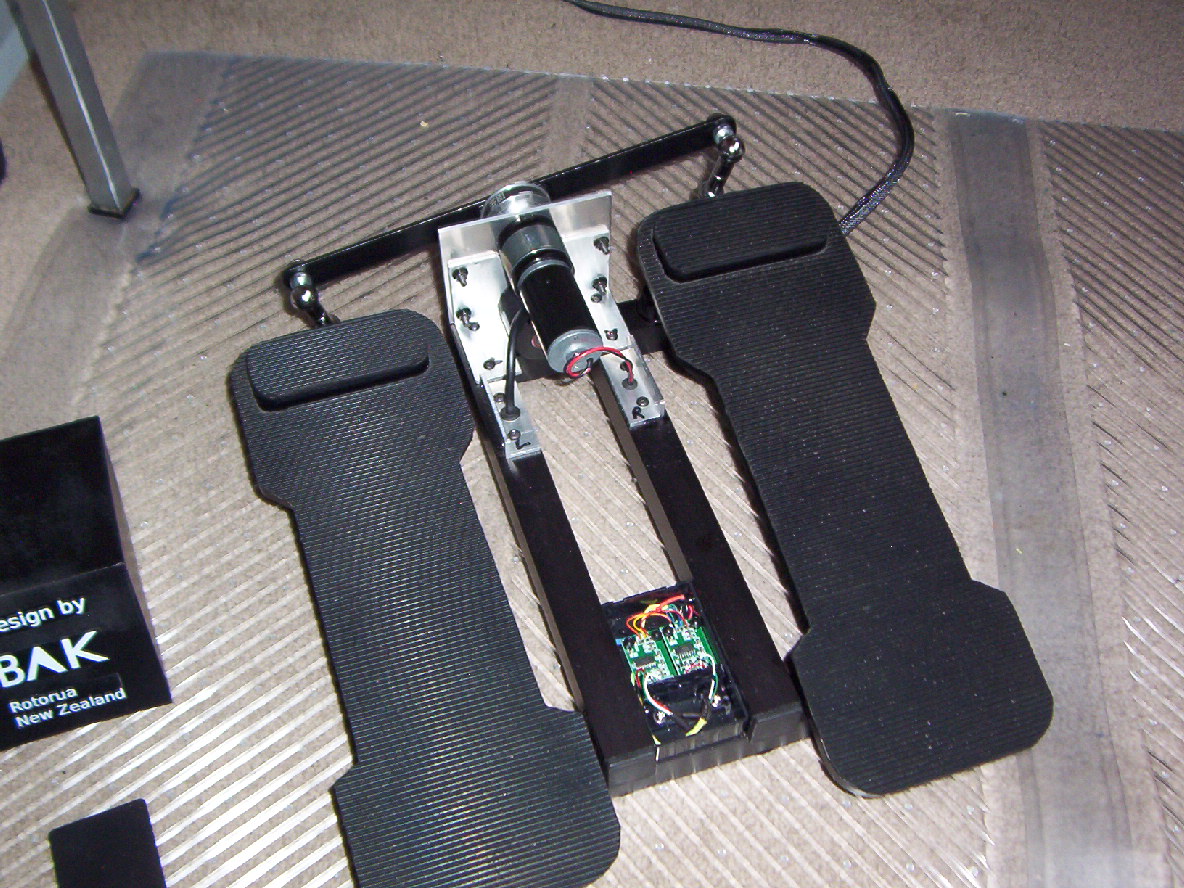
The foot control unit consists of two foot peddles which are connected via ball joints to a rotate bar that is attached to a 60 tooth GT2 pulley. The 60 tooth GT2 pulley is fitted to a 12 volt DC geared motor which can provide torque to the foot peddles. Also attached to the 60 tooth GT2 pulley via a belt and it is connected to another optical rotary encoder for rudder movement readings. Total travel - at toe end of peddle is approx 60mm - 580 encoder pulses.
On each of the foot peddles there are 20kg load cells for the right and left aircraft wheel brakes. These load cells are wired to an HX711 interface PCB. The Hx711 is located in plastic box - front middle of frame.
The foot control unit is connected via a harness to the console.
- 2 wire - PWM - 12 Volt– Supply for the rudder torque motor.
- 8 wires - 0V & +5v – Supply for the rudder optical rotary encoder and the two load cell HX711 interfaces - (Two data signals for the optical rotary encoder, four data signals for two HX711 interfaces).
The foot control unit was designed to have the peddles in a very flat position to allow use on smooth surfaces. This was to reduce the foot control unit moving away from the user without nailing it to the floor. A flat peddle position also reduces leg strain. The foot control unit can still be mounted in a more upright position if desired.
I found I had to use a 12 volt DC geared motor for the foot torque rather than a direct drive as done with the hand controls in the console unit…. All down to hands being more sensitive than feet.
Also found it best to use the foot controls without shoes as it gives better feel with your toes when using the foot brakes.
The cover over the geared torque motor was 3D printed in four pieces using ABS. It was then glued together using dissolve ABS plastic with acetone to create a glue of the same colour.
The cover was coated with some black vinyl auto paint.
The use of ball joints on the end tips of the foot peddles has allowed lighter materials to be used.
I was surprised when I tried connecting the ball joints closer to the hinge area of the foot peddles just how much more pressure occurred on all the linkage mechanism and foot peddles.
A pair of house door hinges were used for the foot peddle hinges. Used ones that don’t have a lot of sideways movement.
The main idea was to keep the foot control unit to a simple design and make the construction simple.
The foot brake pads were kept simple as they are only used during taxing and final landing.
Calibration of the foot brakes load cells didn’t create any issues.
The main concern is you have to calibrate each foot pad one at a time, thus you need to get the same pressure on each foot pad (load cell). I found it took a couple of goes to get it right.
I did test this foot unit on its own with a Arduino Pro Micro without using the torque motor and found it very good for controlling an aircraft in Flight Simulator – Rudder - Left & Right Wheel Brakes.
The peddles won’t centralize without the torque motor but it wasn’t too bad to control. Still I do like having the torque motor feature.
By using a Arduino Pro Micro, the foot control unit could be used as a stand alone unit for flight Simulator. A spring system could be added to centralize the foot peddles.
The Arduino Pro is able to provide the +5 volts for the optical encoder and load cell HX711 PCB’s.
Flight Simulator Control Decals:
A Brother labelling machine that could print white writing on clear tape ( 24mm wide labels) was used for the decals on both the console and foot control units. Doesn’t photograph well but still looks OK.
Software Programs:
I am currently using the flight controls with FS2004 (Plan to upgrade soon) on a Windows 10 PC.
I am using a program called Link2FS -A big thanks to Jim (from New Zealand) in providing this program which allows the direct input and extraction of signals between Arduino processors and Flight Simulator programs.
One of the things with Link2FS you still need to have a joystick to input certain control movements.
Flight Simulator Control Console Processors
Four Arduino Processors: 2 x Leonardo, 2 x Uno.
Arduino Processor # 1 - (Leonardo – Note: must be a Leonardo to be used as a Joystick)
- Communicate data to PC - Runs a joystick library and thus is seen as a joystick.
- Outputs joystick data for : Aileron – Elevator – Rudder – Throttle – Mixture - Left Wheel Brake - Right Wheel Brake.
- Communicates via I2C to
- Processor # 2 Obtains Throttle, Mixture and Foot Brake data.
- Processor # 3 Obtains Engine RPM and Airspeed - used for torque motors
- Aileron – Elevators – Rudder.
- Processor # 4 Obtains switch status for Carb Heat and Magneto settings – used to reduce
engine RPM as FS2004 doesn’t do this function.
Arduino Processor # 2 - (Leonardo )
- This monitors the acoustic sensors for Throttle - Mixture and foot brake sensors.
- Only communicates data to Processor #1.
Arduino Processor # 3 - (Uno)
- Communicates data from PC via Link2FS and outputs data to Processor # 1 via I2C
- This is used to extract flight data from Flight Simulator via Link2FS.
- (Flap position, Elevator Trim Position, Engine RPM, Air speed).
- Controls RC servo motors to display Flap setting and Elevator Trim.
Arduino Processor # 4 - (Uno)
- Communicates data to PC via Link2FS and Processor # 1 via I2C
- This is used to input console panel switch status to Flight Simulator via Link2FS
- Uses a 6 x 5 Matrix with diodes in line with each switch contact to read switch status.
- ( as multiple switch contacts can be active, diodes must be used).
Rotary Encoders:
One of the issues with using rotary encoders to monitor control movements is that you have to use Arduino interrupts to monitor any movements. Basically if a movement occurs, you need to stop running the main program and update the encoder counters, thus the need to use I/O interrupts
To get the best resolutions you need to use two interrupts for each rotary encoder. This means 6 interrupts for 3 rotary encoders. The other thing with rotary encoders is that they are excellent in keeping track of movement distance and direction but not there physical actual position. To obtain actual position I have the processor encoder count programmed as not to go below the minimum count or go above the maximum count. This means on power up a movement of the control fully one way and then the other way automatically sets the encoder counter to the correct physical position. As it is a standard preflight procedure to move controls though there full movements this syncs the encoder movement counters correctly.
I did try using the DC motors to move the controls on power up, but found it better not too and just rely on the pre-flight procedure.
On thing I did find with Flight simulator FS2004 was that a flight can start with different panel switch positions. As not to over load the USB ports, I have only changes of switch data being outputted. On normal startup and flight select, I don’t have an issue, but have found sometimes resetting a flight the switches aren’t set to the default.
I added that the if the primer switch is pulled, it outputs all the switch settings thus saving having to toggle each switch or use Link2FS to disconnect and re-add the Arduino #4 .
================================================================
Overall this has been an interesting project…
I do like the torque effect on the controls. The controls are easy to move when the aircraft is on the ground and the aircraft engine is off.
The torque on the controls increases when the engine is started and as airspeed increases the torque increases more. Very nice when flying loops as you fly the aircraft downwards to built up speed and then pull back and the airspeed slowly drops away at the top of the loop and then increases again as you descend and then you have to pull back up..
This project has been very similar to designing and building a 3D printer.
Major difference has been, working out which Arduino processor I/O pins that I needed to use on each of the four Arduino processors. - Interrupts, PWM, I2C, Analog, digital.
Due to the limited number of I/O pins on the Arduino #1 Leonardo and the functions I required, I ended up having to use another Arduino - Arduino processor #2. This required using I2C communications to be able to get the data back to Arduino #1 for the acoustic and load cell sensors.
Also used I2C communications to get data back from the other two Arduino processors.
Then there was all the programming of the four Arduino’s.
Started off programming each function to prove it worked then combined them all together..
One issue I had was changing the default PWM frequency for the driving of the torque motors.
I had to increase the frequency for timer 3 and timer four – too low you hear the motors squealing and too high the motors don’t run.
A lot of time went into working out sizes and positions for the controls. I really had nothing much to go on apart from measuring peoples hands and feet to be able to designed the components to a useable size and position.
I can say I have enjoyed designing and building the Flight Simulator Controls and have again learnt a LOT more… And it all started with getting involved with building 3D printers.
REPROT - BAK - Rotorua New Zealand.
Having learnt to fly Cessna 152's and 172's a few years back, I wanted a set of controls based on the Cessna 172 design and I wanted them to have a more realistic look and feel, however I didn’t want a set of controls that would take over my computer desk area like a cockpit.
After a lot of brain rattling, design and construction time, I came up with a design that consists of a Flight Simulator Control Console and a Flight Simulator Control Foot Unit.
Flight Simulator Control Console:
The console unit consists of a 19” rack cabinet ( U3). I didn’t use the front 19” panel due to the thickness of the aluminium. This gave me a metal box 420mm x 127mm 335 WxHxD. I kept the rack handles as it makes it easier to move about.
On the front of the console I have the main flight control handle for the aileron and elevator. This was 3D printed in 5 parts and screwed together using 2.5 mm diameter screws. Within the handle are 2 tactile SPST switches with resistors providing a 2 wire connection for an analog reading to determine which of the two switch’s is pressed.
The flight control handle is attached via a flange to a 12mm hollow stainless steel shaft and this is connected to a DC 12 volt motor which can apply rotation torque pressure. Also attached to the DC motor is a GT2 pulley and this is connected via a belt to an optical rotary encoder for aileron movement readings. The rotary encoder is a 600 pulse per revolution – 2 phase. Being two phase, this encoder can give 2400 pulses per revolution although it can only rotate 213 degrees giving 1420 encoder pulses.
The DC motor and optical rotary encoder are mounted on an aluminium bracket that is attached to two 12mm linear bearings which allows the control handle to be moved back and forth for elevator control.
Attached to this assembly there is a GT2 belt that connects onto another DC motor and optical encoder to provide torque and elevator movement readings. This gives a full elevator movement of approx 130mm – 4978 encoder pulses .
Across the front of the console are a number of switches which are laid out similar to the Cessna 172 aircraft. The rotary switches are 12 position types that can be limited to a set number of switch positions. These are used for: Fuel tank selection, Flaps position, Ignition/Magneto, Panel/Radio light dimmer.
- The Ignition/Magneto switch has been modified by using a soldering iron to change the internal detent to make it spring back from the start position. A custom made knob was made to look like a key in a lock.
- The Master Alt/Batt switch is a dual 1 pole switch which has been modified by fitting a small steel shaft to make it operate like the Cessna switch. (There are only 3 setting that can happen with this switch)
The panel/radio light dimmer switch while it is wired its not currently being used. It is reserved for future use if an instrument panel is used (Can provide a digital I/O or PWM signal if required for external light dimming).
Other switches are used for: Aircraft Lights, Pivot heat, Fuel pump, Carb heat, Parking brake, Primer.
The primer switch is a toggle type and was modified to not lock on.
On the front panel there is an elevator trim wheel, this was 3d printed and it has been fitted onto a mechanical rotary encoder. It can continuously rotate – no mechanical stop position.
Also there is a throttle and mixture sliding controls, the knobs were 3D printed and are attached to a 12 mm shaft that slides though a linear bearing. On the rear of the 12mm shaft there is a square block of Teflon which has been drilled out and a spring and round rubber piece fitted (tap seal) , this arrangement stops the knobs rotating and provides some resistant when sliding the control. On the rear of each of the square Teflon blocks there is a metal plate. I am using acoustic sensors to determine throttle and mixture position and the metal plate allows a good echo.
The acoustic sensors mounting supports were 3D printed.
On the front panel there are two indicator levers for displaying Flap position and Elevator trim. These are driven from RC servo motors.
On the rear of the console there is a mains power socket (230VAC) with a mains power On/Off switch that also includes a mains power fuse.
After the mains power switch, power is connected to an 8 amp 12volt DC power supply. The power supply output (12 volt DC) is connected to a fuse block and then is connected to four Arduino processors as well as two dual H-bridge driver PCB’s.
The two dual H-bridge driver’s supply DC power to the aileron, elevator and rudder DC torque motors.
(Only half of the second H-bridge circuit is used).
There are two connectors on the rear panel, these are for the output for the foot control unit rudder DC torque motor power, and logic data signals.
There is a USB female to female connector on the rear panel. I use a male to male USB cable from the PC.
Connected to the USB female connector is a 4 port switched hub. For normal use all the USB switches are off. With the flight simulator mains power off, the PC doesn’t see any USB devices. Only when the
flight simulator mains power is turned on will the PC see the USB devices.
This setup makes it easy when loading programs to any of the four Arduino’s. With the flight simulator mains power off, I can just turn on the switch on the Hub for the Arduino I wish to program.
With having multiple same types Arduino’s connected to a PC, it’s normally hard to determine which PC port is connected to which Arduino when they are the same name type.
Flight Simulator Control Foot Unit:
This is an original design… took a lot of brain rattling to come up with this…
The foot control unit consists of two foot peddles which are connected via ball joints to a rotate bar that is attached to a 60 tooth GT2 pulley. The 60 tooth GT2 pulley is fitted to a 12 volt DC geared motor which can provide torque to the foot peddles. Also attached to the 60 tooth GT2 pulley via a belt and it is connected to another optical rotary encoder for rudder movement readings. Total travel - at toe end of peddle is approx 60mm - 580 encoder pulses.
On each of the foot peddles there are 20kg load cells for the right and left aircraft wheel brakes. These load cells are wired to an HX711 interface PCB. The Hx711 is located in plastic box - front middle of frame.
The foot control unit is connected via a harness to the console.
- 2 wire - PWM - 12 Volt– Supply for the rudder torque motor.
- 8 wires - 0V & +5v – Supply for the rudder optical rotary encoder and the two load cell HX711 interfaces - (Two data signals for the optical rotary encoder, four data signals for two HX711 interfaces).
The foot control unit was designed to have the peddles in a very flat position to allow use on smooth surfaces. This was to reduce the foot control unit moving away from the user without nailing it to the floor. A flat peddle position also reduces leg strain. The foot control unit can still be mounted in a more upright position if desired.
I found I had to use a 12 volt DC geared motor for the foot torque rather than a direct drive as done with the hand controls in the console unit…. All down to hands being more sensitive than feet.
Also found it best to use the foot controls without shoes as it gives better feel with your toes when using the foot brakes.
The cover over the geared torque motor was 3D printed in four pieces using ABS. It was then glued together using dissolve ABS plastic with acetone to create a glue of the same colour.
The cover was coated with some black vinyl auto paint.
The use of ball joints on the end tips of the foot peddles has allowed lighter materials to be used.
I was surprised when I tried connecting the ball joints closer to the hinge area of the foot peddles just how much more pressure occurred on all the linkage mechanism and foot peddles.
A pair of house door hinges were used for the foot peddle hinges. Used ones that don’t have a lot of sideways movement.
The main idea was to keep the foot control unit to a simple design and make the construction simple.
The foot brake pads were kept simple as they are only used during taxing and final landing.
Calibration of the foot brakes load cells didn’t create any issues.
The main concern is you have to calibrate each foot pad one at a time, thus you need to get the same pressure on each foot pad (load cell). I found it took a couple of goes to get it right.
I did test this foot unit on its own with a Arduino Pro Micro without using the torque motor and found it very good for controlling an aircraft in Flight Simulator – Rudder - Left & Right Wheel Brakes.
The peddles won’t centralize without the torque motor but it wasn’t too bad to control. Still I do like having the torque motor feature.
By using a Arduino Pro Micro, the foot control unit could be used as a stand alone unit for flight Simulator. A spring system could be added to centralize the foot peddles.
The Arduino Pro is able to provide the +5 volts for the optical encoder and load cell HX711 PCB’s.
Flight Simulator Control Decals:
A Brother labelling machine that could print white writing on clear tape ( 24mm wide labels) was used for the decals on both the console and foot control units. Doesn’t photograph well but still looks OK.
Software Programs:
I am currently using the flight controls with FS2004 (Plan to upgrade soon) on a Windows 10 PC.
I am using a program called Link2FS -A big thanks to Jim (from New Zealand) in providing this program which allows the direct input and extraction of signals between Arduino processors and Flight Simulator programs.
One of the things with Link2FS you still need to have a joystick to input certain control movements.
Flight Simulator Control Console Processors
Four Arduino Processors: 2 x Leonardo, 2 x Uno.
Arduino Processor # 1 - (Leonardo – Note: must be a Leonardo to be used as a Joystick)
- Communicate data to PC - Runs a joystick library and thus is seen as a joystick.
- Outputs joystick data for : Aileron – Elevator – Rudder – Throttle – Mixture - Left Wheel Brake - Right Wheel Brake.
- Communicates via I2C to
- Processor # 2 Obtains Throttle, Mixture and Foot Brake data.
- Processor # 3 Obtains Engine RPM and Airspeed - used for torque motors
- Aileron – Elevators – Rudder.
- Processor # 4 Obtains switch status for Carb Heat and Magneto settings – used to reduce
engine RPM as FS2004 doesn’t do this function.
Arduino Processor # 2 - (Leonardo )
- This monitors the acoustic sensors for Throttle - Mixture and foot brake sensors.
- Only communicates data to Processor #1.
Arduino Processor # 3 - (Uno)
- Communicates data from PC via Link2FS and outputs data to Processor # 1 via I2C
- This is used to extract flight data from Flight Simulator via Link2FS.
- (Flap position, Elevator Trim Position, Engine RPM, Air speed).
- Controls RC servo motors to display Flap setting and Elevator Trim.
Arduino Processor # 4 - (Uno)
- Communicates data to PC via Link2FS and Processor # 1 via I2C
- This is used to input console panel switch status to Flight Simulator via Link2FS
- Uses a 6 x 5 Matrix with diodes in line with each switch contact to read switch status.
- ( as multiple switch contacts can be active, diodes must be used).
Rotary Encoders:
One of the issues with using rotary encoders to monitor control movements is that you have to use Arduino interrupts to monitor any movements. Basically if a movement occurs, you need to stop running the main program and update the encoder counters, thus the need to use I/O interrupts
To get the best resolutions you need to use two interrupts for each rotary encoder. This means 6 interrupts for 3 rotary encoders. The other thing with rotary encoders is that they are excellent in keeping track of movement distance and direction but not there physical actual position. To obtain actual position I have the processor encoder count programmed as not to go below the minimum count or go above the maximum count. This means on power up a movement of the control fully one way and then the other way automatically sets the encoder counter to the correct physical position. As it is a standard preflight procedure to move controls though there full movements this syncs the encoder movement counters correctly.
I did try using the DC motors to move the controls on power up, but found it better not too and just rely on the pre-flight procedure.
On thing I did find with Flight simulator FS2004 was that a flight can start with different panel switch positions. As not to over load the USB ports, I have only changes of switch data being outputted. On normal startup and flight select, I don’t have an issue, but have found sometimes resetting a flight the switches aren’t set to the default.
I added that the if the primer switch is pulled, it outputs all the switch settings thus saving having to toggle each switch or use Link2FS to disconnect and re-add the Arduino #4 .
================================================================
Overall this has been an interesting project…
I do like the torque effect on the controls. The controls are easy to move when the aircraft is on the ground and the aircraft engine is off.
The torque on the controls increases when the engine is started and as airspeed increases the torque increases more. Very nice when flying loops as you fly the aircraft downwards to built up speed and then pull back and the airspeed slowly drops away at the top of the loop and then increases again as you descend and then you have to pull back up..
This project has been very similar to designing and building a 3D printer.
Major difference has been, working out which Arduino processor I/O pins that I needed to use on each of the four Arduino processors. - Interrupts, PWM, I2C, Analog, digital.
Due to the limited number of I/O pins on the Arduino #1 Leonardo and the functions I required, I ended up having to use another Arduino - Arduino processor #2. This required using I2C communications to be able to get the data back to Arduino #1 for the acoustic and load cell sensors.
Also used I2C communications to get data back from the other two Arduino processors.
Then there was all the programming of the four Arduino’s.
Started off programming each function to prove it worked then combined them all together..
One issue I had was changing the default PWM frequency for the driving of the torque motors.
I had to increase the frequency for timer 3 and timer four – too low you hear the motors squealing and too high the motors don’t run.
A lot of time went into working out sizes and positions for the controls. I really had nothing much to go on apart from measuring peoples hands and feet to be able to designed the components to a useable size and position.
I can say I have enjoyed designing and building the Flight Simulator Controls and have again learnt a LOT more… And it all started with getting involved with building 3D printers.
REPROT - BAK - Rotorua New Zealand.
|
Re: PC Flight Simulator controls November 01, 2018 03:14AM |
Registered: 8 years ago Posts: 5,232 |

|
Re: PC Flight Simulator controls November 01, 2018 03:53AM |
Registered: 14 years ago Posts: 128 |
Hi,
As the controls are moved away from their central position a PMW signal is sent via the a 7amp H-bridge driver to try and drive the motor back to its central position.
The more the control is moved, the higher rate of PWM is generated. When the controls are centred, I have a small null area where no PWM signal occurs.
All 3 controls are self centering.
The motors draw about 2 - 3 amps. While the motors aren't designed as a torque motor they seem to work quite well.
The console was the main thing I planned on building then I thought I should build a set of foot peddles, couldn't find anything that I liked out on the internet.
That's where the original bit comes in. The use hanging ball joints from a bar and connected at the end of the peddles to create the differential peddle movement.
Haven't seen anyone do that yet...
Cheers BAK
|
Re: PC Flight Simulator controls November 01, 2018 04:15AM |
Registered: 10 years ago Posts: 14,672 |
Very nice! I used to fly light aircraft too, so I am aware of the need for good feedback from the controls, which the off-the-shelf flight simulator controls don't do.
The use of ultrasonic sensors to track the control positions is a neat idea! I haven't seen that done before.
Regarding rotary encoders, you don't have to use interrupts with them if you use an appropriate driver, you just need to poll them every few milliseconds. I use this driver: [github.com]. If the main loop of the program is too slow for polling them then I poll them in the tick interrupt service routine. When using several rotary encoders, I multiplex them to save on pins. I connect diodes between each of the A pins of the encoders to a common A input of the MCU. Similarly for the B pins, and also for the push button pin if I am using it. Then I connect each common pin on a rotary encoder along with the other push button pin to its own MCU pin. This reduces the number of MCU pins needed to support N rotary encoders with push buttons from 3N to 3 + 2N. Further savings can be made by multiplexing other switches or push buttons into the same MCU pins, or by using a 74HC138 3-to-8 line decoder to drive the common pins of the rotary encoders - although at that point it is usually simpler to switch to an MCU with more pins.
Large delta printer [miscsolutions.wordpress.com], E3D tool changer, Robotdigg SCARA printer, Crane Quad and Ormerod
Disclosure: I design Duet electronics and work on RepRapFirmware, [duet3d.com].
|
Re: PC Flight Simulator controls November 01, 2018 03:51PM |
Registered: 14 years ago Posts: 128 |
Thanks for that David,
I can see a need for your encoder driver... Using it for a radio panel would be really great with lots of encoder switches.
All comes down to making sure you catch the encoder change and as its only a hand movement on the encoders, speed is not that great.
I think I would still have run out of I/O's even having the encoders sharing I/O pins on the Leonardo processor.
The elevator trim encoder is wired to the fourth Arduino which also monitors all the panel switches. Had the Leonardo enough I/O pins then your encoder driver would have been the answer as I am already used up all of the 6 interrupt pins you can have with the Leonardo.
With using ultrasonic sensors and I2C communications on the second Leonardo processor, I had to add that after sending a echo that if I2C communications occurred before the echo is returned that the reading was ignored.
Slightly different situation to encoders but again making sure you don't miss something.
Just received a Nextion 7" LCD panel that I am going to see if I can add flight simulator gauges to it.. Would properly need two panels to do all the gauges.
Not sure whether this is better than using the monitor screen. If not I properly have another projects for it.
Will be interesting to see if I can do a altimeter with it having 2 needles. I don't see issues with using the Nextion editor software with single needle gauges.
Thanks again
Cheers Bruce
Sorry, only registered users may post in this forum.