Flight Simulator Aircraft Gauges – Instruments (Arduino controlled)
Posted by RepRot
|
Flight Simulator Aircraft Gauges – Instruments (Arduino controlled) August 26, 2021 07:10PM |
Registered: 14 years ago Posts: 128 |


In the pursuit of a more realistic flight simulator controls and display and also having already designed and built a control console and foot controls with force feedback; I thought I would try and design and build a set of aircraft gauges. I used my 3D printer that I had built to make a lot of the gauge parts.
With each aircraft generally having a set of gauges that are suited for its design and having already built controls based on the Cessna 172 I therefore based my gauge designs on the Cessna 172 aircraft.
I am using the following PC programs:
Prepar3D version 5- Flight Simulator.
A2 Simulator Cessna 172 aircraft addon.
FSCUIPC Registered version for Prepar3D v5 . (Used for extraction of data from Prepar3D to Arduino processors).
One of my requirements was not to have a real sized cockpit layout, rather a more compact setup that wouldn’t take over my computer room space.
One of the differences with aircraft gauges that are displayed on a monitor flat screen and a physical gauge is that physical gauges have a lesser viewing angle due to there depth. Therefore I had to consider the size I was going to make my gauges and to where I was going to position them.
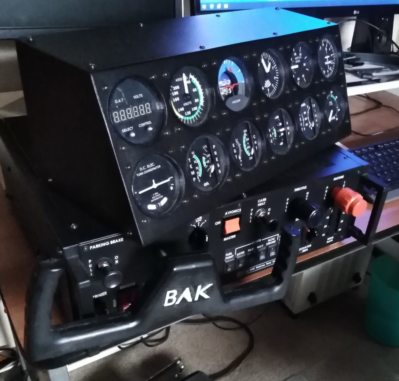
The other thing I had to consider is that I wanted to have a total of 12 gauges that would be arranged in two rows of 6 gauges that would fit in a box on top of my existing control console being 425mm wide.
With some gauges being a dual type and others requiring different drive motors I worked out that I could reduce the size of the gauges to 70mm x 70mm (height x width) with a panel hole of 65 mm diameter with a viewing size of 60mm diameter. This is slightly smaller than normal aircraft gauges.
The other thing I needed to do was to mount the gauges in a box with a sloping front to provide a better viewing angle.
--------------------
Overall it’s been an interesting project, somewhat of a learning curve and not a quick project....
I am pleased with the finished product and it’s enjoyable to use…
And it all started after I started building 3d printers some years ago….
----------------------------------------------------------------------------------------------------------------------------------------
Warning: Only read the following if you wish to now about the technical stuff…. .
Gauge Motors:
I have used Switec X27 automotive geared stepper motors for the single axis pointers gauges
They can be purchase from the likes of Aliexpress and Ebay for a couple of dollars each.
I also used Switec X40 automotive geared stepper motors for the dual pointer single axis gauges.
The X40 is a dual version of the X27. The X40 motors are end to end with the output shafts inside the other.
They can be purchased from Aliexpress for about five times the price of an X27.
The X27 & X40 geared stepper motors are low current motors and can be driven from 5v to 9v. They contain two coils for each motor unit (4 wire connections for each motor).
Wire leads can be soldered onto the motor connections.
X27 & X40 have 315 degrees of rotation with an internal mechanical stop.
The X27 & X40 geared stepper motors are used in many vehicles for speedometer and tachometers.
You can connect and drive these gauge motors directly from an Arduino micro processor input/output pin (I/O).
Information about this can be found on the internet.
While the X27/X40 can be connected directly to the Arduino pins, protection diodes should really be used to stop the possibility of electrical spikes damaging the Arduino.
I tried this direct connect method but found that it didn’t provide a very smooth movement. My next thing was to try using micro stepping.
I then tried using a spare Polulu stepper driver which uses the A4988 driver chip. I had to supply a driver voltage of at least 8 volts for the A4988 to allow an output to the stepper motor. I found using the A4988 with micro stepping produced a lot smoother movement. However the stepping count wasn’t correct and movement was noisy.
Looking into this issue I found that the X27 & X40 style stepper motors use a 6 stage stepping sequence where as the A4988 stepper driver commonly used for Nema type motors use an 8 stage stepper sequence.
I then tried a AX120728SG driver chip which is equivalent of the VID6606 (Uses 6 stage stepping sequence). This produced a lower noise and smoother movement . Note: Refer to the VID6606 datasheet for the AX120728SG specs.
The AX120728SG driver chip is a surface mount device. However they can be hand soldered onto a SOP28 adapter boards. These adapter boards can be purchase for about $0.40 each. It can be a bit tricky to get all the pins connected first time but not impossible. With soldering 140 pins I failed with 3, even testing them with a meter won’t always indicate that you haven’t soldered them properly.
Each AX120728SG can drive 4 stepper motors. It requires a step and direction input signal for each stepper motor and has a reset pin which needs to be held high and requires a +5 volt supply.
As the X27 & X40 motors have no output to determine the output shaft position. An initial homing function needs to be performed to determine the shaft position.
With a mechanical 315 degree of movement, the trick is to send it enough step pulses as to move it to an end stop limit position. As you properly don’t know where the motor is, it means sending it the amount of pulses that would move the motor though it’s full range.
I did find that once the motor reaches its full movement and you keep sending pulses, it does produce a small amount of noise. This doesn’t cause damage to the motor.
I found on startup of my complete gauge display unit, which has multiple gauge stepper motors all homing at once, it can produce quite an amount of noise. This is subject mainly to the issue of the motors hitting against the end stops.
I found I could reduce this homing noise by knowing where the motor were when last used.
I built into my Arduino program for controlling the gauges that if no data was received from the PC for a set time, then certain gauges would be moved to their zero position. I used the flight simulator “TIME” extraction data as it is always being updated every second.
While this reduces the issue with noise with the motors hitting the end stops on powering up, the down side is if you pause the flight simulator, some gauges will move to the zero position. On un-pausing they then move back and indicate as they should. I don’t find this a major issue.
Gauge pointers:
I 3D printed gauge pointers (needles) for the X27 & X40 stepper motors.
The X27 motor has a 1 mm diameter shaft.
The X40 motor has a 1 mm diameter inner shaft and a 2.5 mm outer shaft.
It can be difficult to glue the pointers correctly in position. Fortunately I found I didn’t need to use the full 315 degrees of movement.
What I did in the programming was to have an offset variable for allowing fine tuning of the zero gauge position.
The gauge label zero position is usually further away from the start movement end stop.
I also use a variable for the gauge full movement step count as some gauge motors have been modified for reduced movements.
For homing (knowing the last position being zero), I move the gauge forward (full movement less the offset), then move it backwards (full movement) and then move forward (offset) and set the gauge position counter at zero. This reduces the noise of the motor being driven against the end stops and ensures gauges are in there correct position.
Normal mounting of the X27 & X40 motors is by soldering the motor coil connections to a PCB, however I found I could use two M2x12mm counter sunk screws that will self tap into the existing holes in the X27 & X40 housing. Care needs to be taken as not to place any warping pressure onto the X27 & X40 plastic casing, as this can damage the motors gear meshing which can result in noisy or non operation. Best to self tap screws before motor is fitted to motor mounting plate
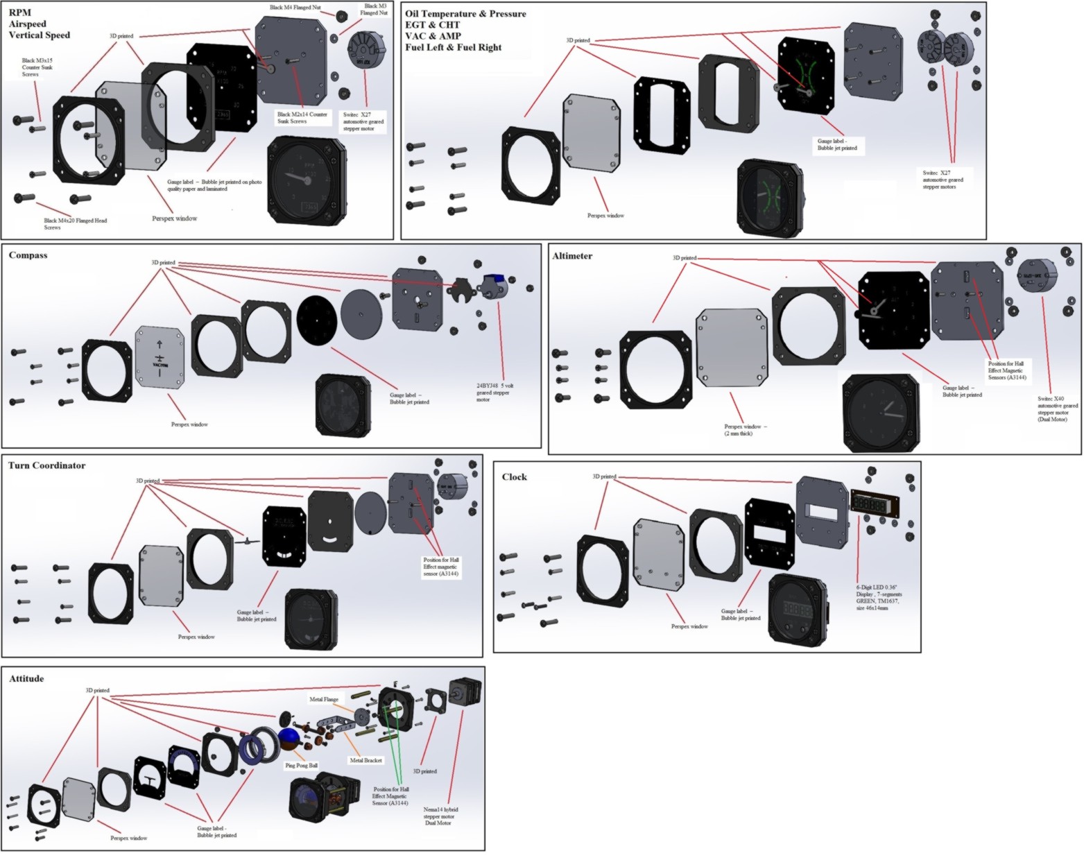
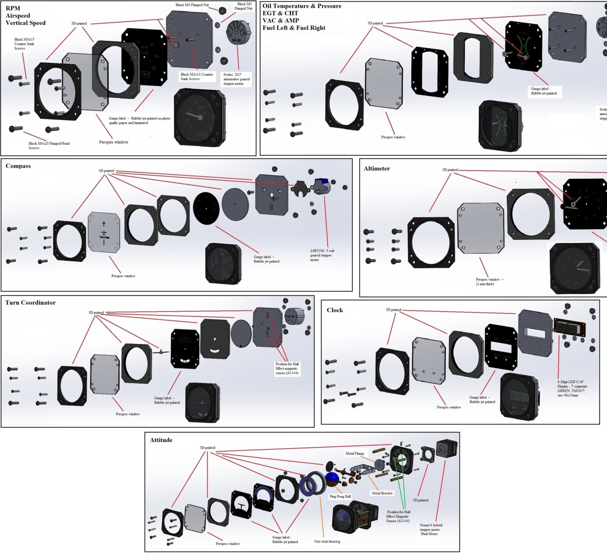
Gauge Construction:
I designed the gauges to be a number of parts that are laminated together which allows many of the same parts to be used for different gauges
- Front bezel – 3D printed
- Perspex window – (2 mm thick)
- Gauge label – Bubble jet printed. (Only some gauges have this label, two motors type)
- Spacer – 3D printed - (5 mm thick) (Can have two 3mm LED’s for night flying).
- Pointer (Needle) – 3D printed
- Gauge label - Bubble jet printed
- Motor mounting plate – 3D printed
Four M3x25mm counter sunk screws with flanged nuts are used to hold the gauge parts together and four black M4 x 25mm flanged head screws with flanged nuts are used for fixing the gauge to the gauge box front panel.
I created the gauge labels using the free download Inkscape program. SVG format was used to create clean edged images that can also be scaled without loss of quality unlike Jpeg/bmp. The images were bubble jet printed onto white photo quality paper and then laminated with clear plastic. Holes in the labels were then made using hole punches for the required screw and gauge holes. The label edges were then coloured with a black felt tip pen.
Gauge Motor Control Software:
All gauge stepper motors use the Arduino AccelStepper library.
You can have multiple numbers of stepper motors using this library with one Arduino.
For each stepper motor, you need to set a Max speed and Acceleration rate. Acceleration rate is both acceleration and de- acceleration. These Max and Acceleration values can be changed within the running program if you need to.
You can set the current position value of the motor at any time.
You also can set the motor to move a set distance from it current position or move to a set count position. However setting the position doesn’t mean the motor moves.
After setting a move, you need to have a run command. This run command needs to be repeated multiple times as it only moves the motor a single step subject to Max speed and Acceleration rates and whether the motor has reached its move position that was set.
You also have a command function to known how much further the motor has to go before its going to get to the move position it was told to go.
You can use commands like this after setting the move position-
while(Stepper1.distanceToGo() != 0 {Stepper1.run();}
This provides multiple runs until the motor gets to the move position it was told to go to.
This is great for homing type movements but for normal flight simulator operation you don’t wish to move to a position that may have been updated with a new lesser movement.
I used Arduino communications interrupts to update the move position and then only in the loop part of the program I have the command for the stepper motor run.
Note: If you have too many commands taking too long in the main program it can slow down the movement of the stepper motor.
To reduce the time it takes to home gauges, I would home some gauges that are controlled by the same nano together. After setting each gauge movement I would use a command like the following..
while(Stepper3.distanceToGo() != 0 ||Stepper4.distanceToGo() != 0){Stepper3.run(); Stepper4.run();}
When designing and building each gauge I wrote two pieces of Arduino software for each gauge…
One allowed me to input data via serial monitor and the second one that allowed me to extract data from flight simulator via the FSUIPC program and compare the physical gauge movement with the gauge on the monitor.
RPM Gauge:
This gauge was the first gauge I designed and built as it is the easiest. Hardware side is fairly straight forward.
I used a fishing line glue for attaching the pointer to the stepper motor shaft
For the software side, the extracted data from flight simulator needs to be scaled to provide the correct movement range.
What I did find later with multiple gauge extractions and that not all gauges have a straight linear scale.
Thanks to Martin Nawrath -- [interface.khm.de]
I was able to create a re-mapping section in the program which allows for linear and non linear scaling for both positive and negative values.
Airspeed Gauge:
This gauge is much the same as the RPM gauge with a different label.
The airspeed gauge uses 3 different scales, e.g. 0 to 40 (half scale) 40 to 160 (normal scale) 160 to 200 (half scale). You can use a few “if” commands to get the correct gauge scale movements. However this is where the use of the re-mapping program section comes in useful.
Vertical Speed Gauge:
This gauge is much the same as the RPM gauge with a different label.
Homing of the gauge requires the pointer to be positioned in the middle of the movement range.
Oil Temperature/Pressure, EGT/CHT, VAC/AMP and Fuel Left/Right Gauges:
Each of these gauges uses two X27 motors side by side:
Note: The positioning of the motors side by side is one of the restrictions to how small all the gauges can be made.
The X27 motors for these dual type gauges require less movement that the standard 315 degree of movement.
The X27 motors can be carefully unclipped and by using a soldering iron, plastic can be melted into the limit channel to reduce the range of movement.
While it may not be easy to get an exact reduced movement with the melted plastic, the use of variables in the program for the range and offset can adjusted for this issue.
Reducing movement of the pointers is required as you don’t want pointers hitting parts of the gauge which may result in the pointers coming un-bonded from the X27 motor.
An additional printed label (center is cut out) is used with these gauges between the gauge window and the spacer.
Turn Coordinator Gauge:
An X40 motor (dual axis motor) is used for the Turn Coordinator gauge as both roll and side slip is required to be displayed.
Note: The X40 motor coil connections are usually facing the output shaft direction. These connections leads can be changed by re-soldering to face the opposite direction.
A white plastic disk which was 3d printed is used for the displaying side slip ball movement. A black circle dot was painted onto the white disk. The white disk has been glued onto the outer shaft (2.5 mm diameter) of the X27 motor.
A 3D printed turn indicator pointer has been fitted to the inner shaft (1mm diameter) of the X27 motor.
Both motors of the X40 motor are homed as like the other X27 motors e.g. RPM, airspeed etc.
An additional spacer is used with this gauge due to the white plastic disk for displaying the slip ball.
A curved slot has been cut out of the printed label to allow viewing of the slide ball.
Compass Gauge:
This gauge requires a stepper motor that has 360 degree of rotation and that it can drive a 3d printed disk (2 mm thick - 55mm diameter) that has a compass label attached to it.
While an X27 motor can have the limit stop removed, it doesn’t have enough strength and speed to rotate a disk at any great speed. The other issue is attaching a compass disk to a 1mm motor shaft that won’t fall off over time.
I used a 24BYJ48 5 volt geared stepper motor. These motors have 360 degree of movement and have a lot more driving force than an X27. The 24BYJ48 requires to be driven by an 8 stage stepper sequence driver.. e.g. DRV8834 , A4988. They also have a 6 mm diameter output shaft with flatten sides, which makes a good bonding area to attach a 3D printed disk. They can be purchase for a few dollars each.
The correct stepper motor current levels needs to be set on the DRV8834 to avoid noisy operation and over heating.
As the 24BYJ48 motor has no output to determine the motor shaft position. A method is required to be able to detect the position of the motor shaft that has the 3d printer disk attached. I have used a hall effect magnetic sensor (A3144) that is attached (glued) to the 3D printed motor mounting plate. On the 3d printer disk I have installed a neodymium (2mm long x 1 mm diameter) magnet. This allows detection of a home position.
The A3144 hall effect magnetic sensor is a 3 wire device. One wire requires +5 volts, another wire requires 0 Volts and the third wire is the sensor output. This sensor output wire can be connected directly to an Arduino I/O pin. It requires that the Arduino internal pull up resistor to be enabled. When the A3144 detects a magnet, the sensor wire is driven low (0 volts).
Homing operation of the compass gauge:
1st – Check the magnetic sensor. If magnet is detected, then move the motor a short distance forward.
(The reason for this is the sensor can sense the magnet though a few degrees of movement.
2nd – Move the motor backwards until the magnet is sensed.
3rd – Move the motor offset distance
(Reason for the offset is it can be difficult to position the printed label on the plastic disk accurately).
4th – Set the Motor position at Zero (e.g. 0 - North).
I painted an image of a plane which shows the heading direction on the gauge window. I did this by using a laser engraver that I had built. I engrave a plane image onto a stick-on label to create a stencil. Using the stencil I painted a white plane image onto the Perspex window.
One of the issues with the compass gauge is the data from flight simulator is just a degree figure 0 -359.
When moving from 359 to 0 degrees or back for 0 to 359 degrees you don’t wish to take the long way around.
Therefore you have to use the current position and determine from the new direction figure which direction and amount of movement is required. The Arduino Modulus formula(%) comes in useful here.
CurrentHeading = Stepper1.currentPosition();
LastHeading = CurrentHeading/11.377778; // The figure 11.377778 is steps/degree
Movement = ((Data + 180 - LastHeading) % 360) - 180
if(Movement < -180){Movement = Movement + 360;}
Stepper1.moveTo(CurrentHeading + (Movement) * 11.377778);} // The figure 11.377778 is steps/degree
Note: The correct stepper motor current level needs to be set on the DRV8834 to avoid noisy operation and over heating.
Altitude Gauge:
A X40 motor (dual axis motor) has been used for the Altitude gauge.
As the altitude gauge requires 360 degree movement the X40 motor was carefully dismantled and the end stop lugs for both motors was cut off.
Note: The X40 gears are very fine and you don’t want a small piece of plastic to get jammed in there.
Motor connection wires were also swapped to have them facing away from the output shaft direction.
The altimeter pointers were 3d printed to allow a small neodymium magnet (2mm long x 1mm diameter ) to be installed on the rear side of both pointers. The larger pointer has the magnet positioned towards its outer end away from the center of the gauge as not to interfere with the smaller pointer.
Two hall effect magnetic sensors (A3144) were mounted into the motor mounting plates. These sensors were positioned 180 degrees from each other and aligned under the pointers magnets
Homing is required for each pointer and is just like the compass homing.
I did find it looks less weird to home one pointer in one direction and the other in the opposite direction.
After the initial homing of both the pointers, the speed for the stepper motor for the smaller pointer (1000 feet) is set at 1/10 the speed of the larger pointer (100 feet).
This allows the pointers to move together at what appears as a clock geared motion.
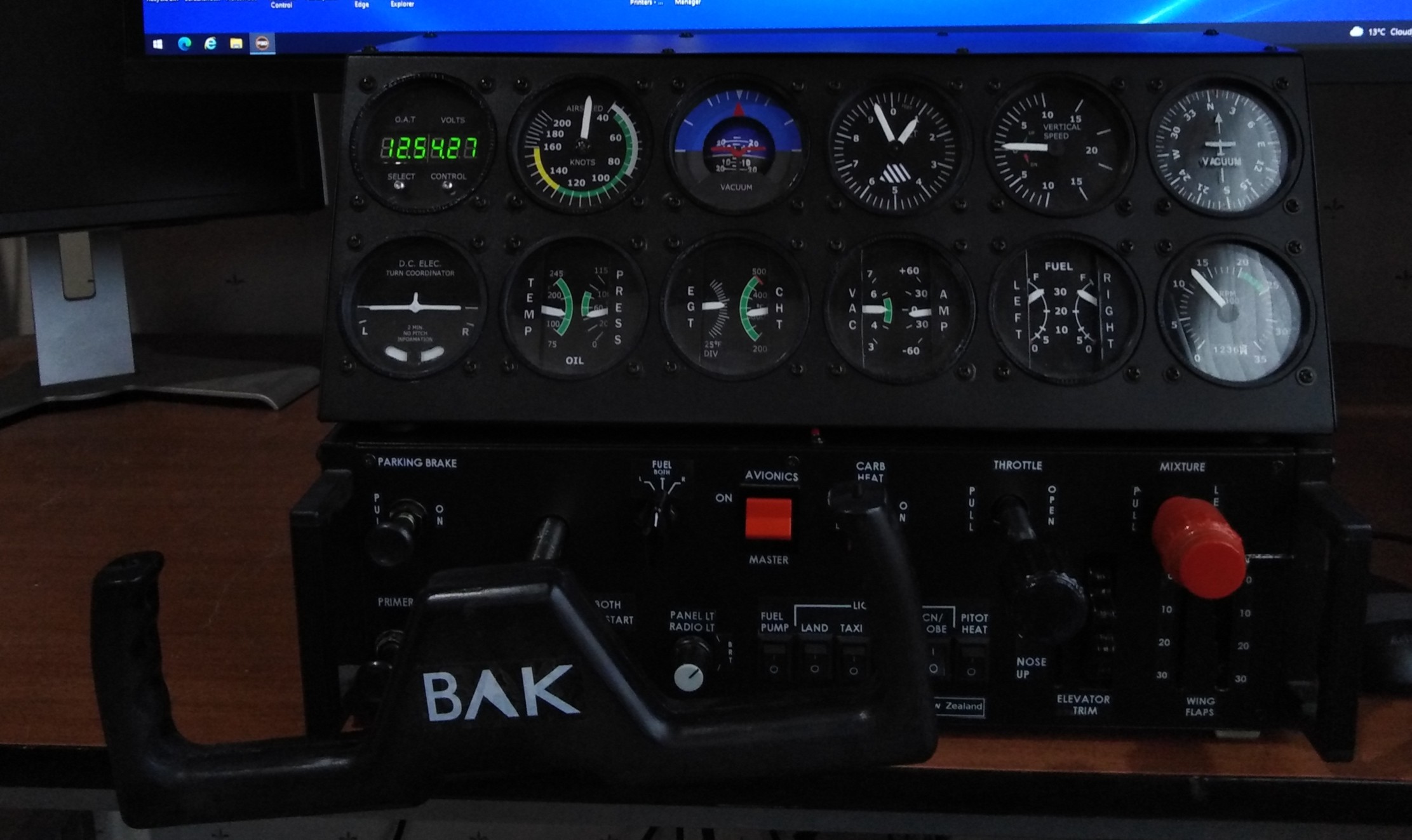
Digital Clock Gauge:
For the digital clock gauge I have used a 6-Digit LED 0.36" Display , 7-segments GREEN, TM1637, size 46x14mm. I control it with the Arduino TM1637_6D.h library.
The 6 digit display can display the Time, Outside Air Temperature (OAT) and Voltage (bus voltage).
6 digits are used with decimal points for TIME. (hh.mm.ss)
3 digits on the left are used with decimal point for OAT ( xx.x )
3 digits on the right are used with decimal point for VOLTAGE ( xx.x)
To select the different display readings, I have used two stainless hex screws located by the Select and Control which would normally be press buttons.
The select one is connected to an Arduino analog pin and functions as a capacitor touch sensor that allows stepping though the three different displays.
Attitude Gauge:
This has been the most challenging gauge to design and build. It has taken some time and effort..
I first tried using two 24BYJ48 geared stepper motors (Same type I used for the compass gauge) to rotate a ping pong ball in two directions via brass gears to display roll and tilt. While I got it to work, movements weren’t fast enough and gear backlash was too much.
I then sourced a larger motor a Nema14 hybrid stepper motor direct from Casin in China. They were very helpful.
The motor cost NZ$20 and freight was NZ$20.
The Nema14 hybrid stepper motor is two stepper motors that are end to end with there output shafts inside the other. (Inner shaft 5 mm dia - Outer shaft 8 mm dia).
Using the Nema14 hybrid stepper motor I was able to directly rotate the ping pong ball without the use of gears and not have any gear backlash issues, Tilting still required the use of gears and using a bit of software I was able to reduced backlash, basically just over drive a bit when moving in one direction.
I used two DRV8834 stepper drivers and the correct stepper motor current levels needs to be set to avoid noisy operation and over heating.
I have used two hall effect (A3144) magnetic sensors for detecting home positions for roll and tilt. These sensors are mounted on a motor support plate. While the rotate sensor will detect every time the ping pong ball rotates, the tilt sensor only will detect when the rotate is in a set position. Thus on initial homing, the rotate motor rotates until detecting the home sensors, it then rotates to a set position to allow the tilt motor to sensor its home position.
Hopefully picture explains how it works..
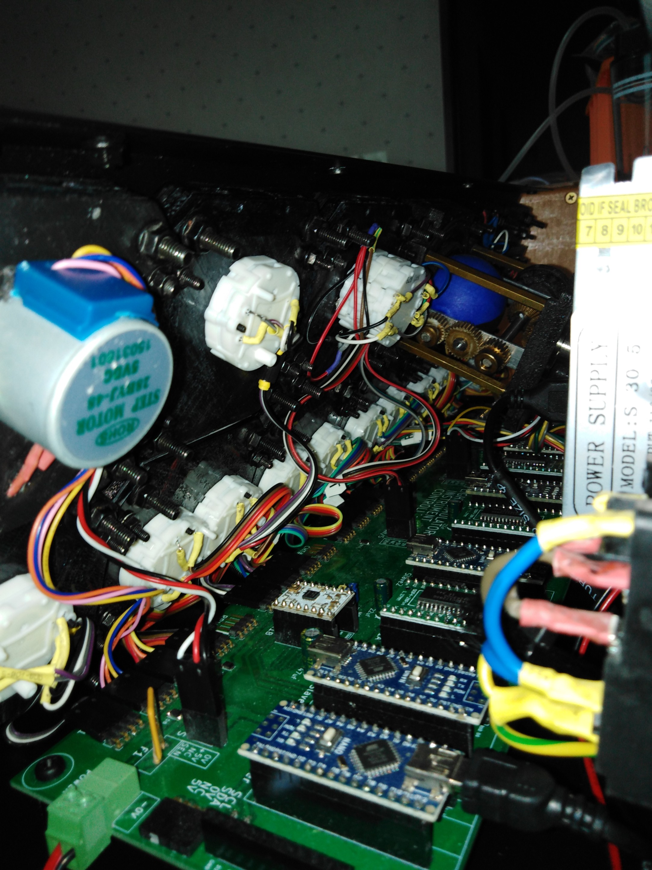
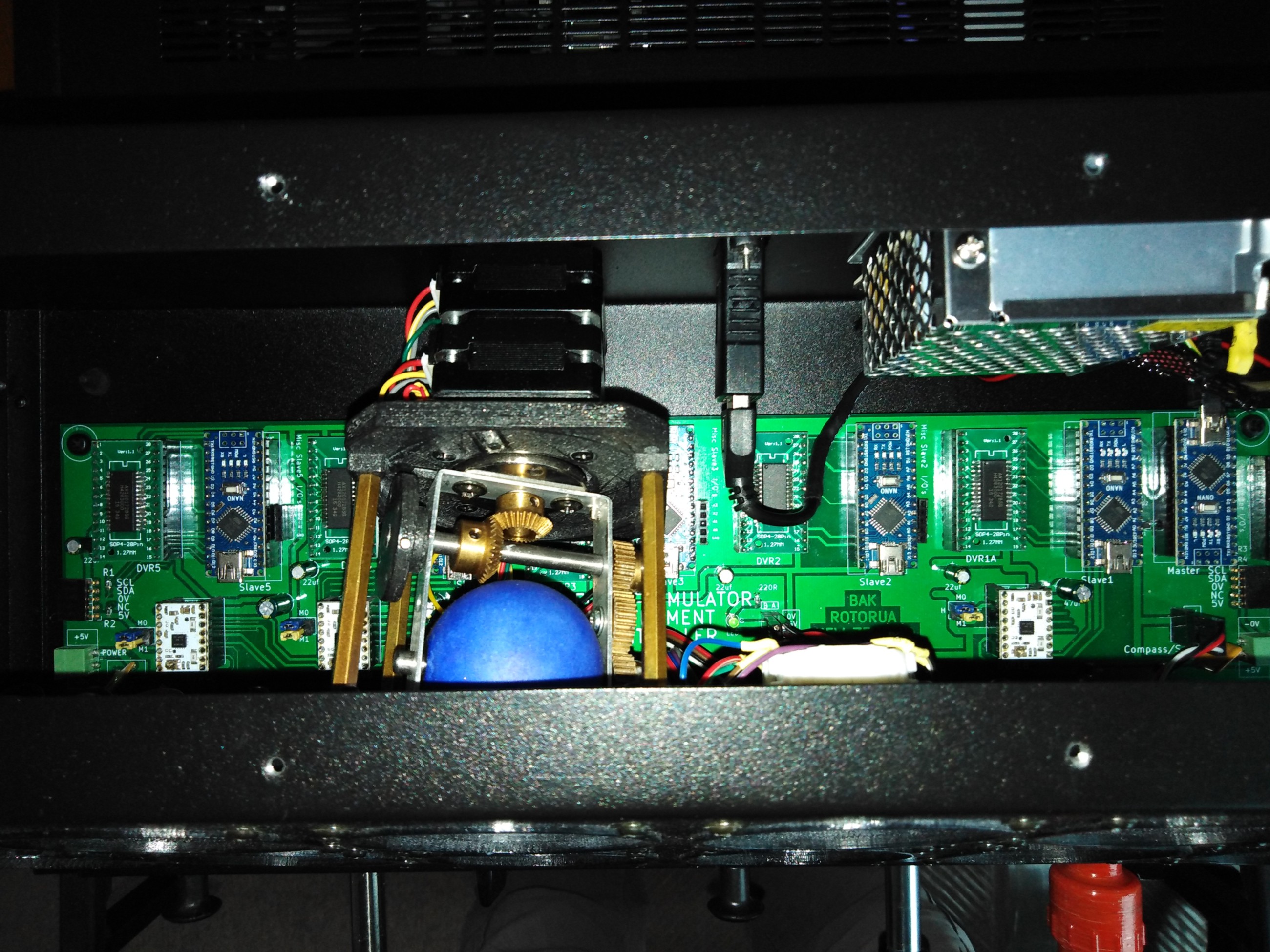
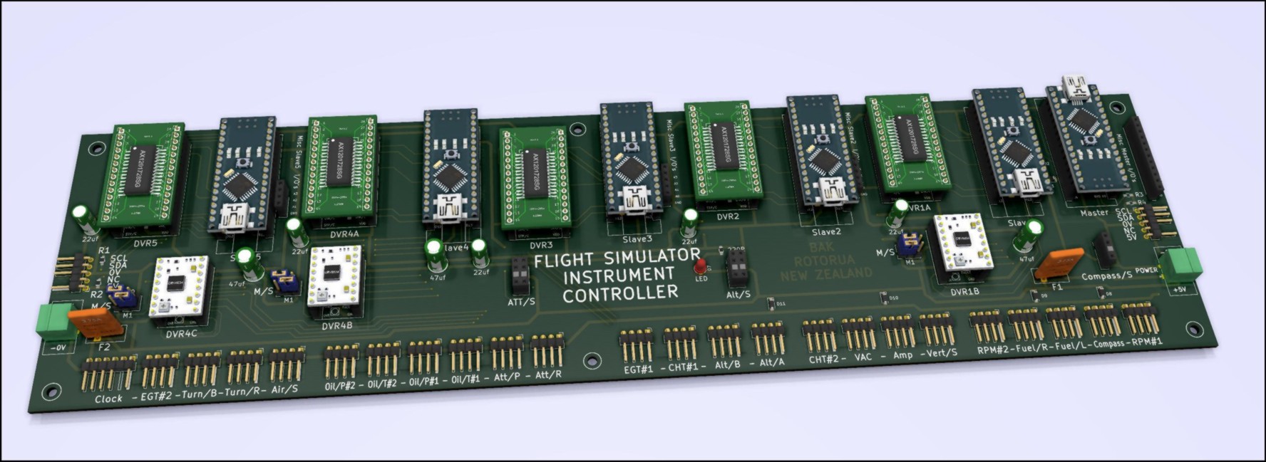
Gauge Controller PCB:
To control the 12 sets of gauges, I designed a two sided 370mm x 100mm circuit board.
I used Kicad PCB program (can be downloaded for free).
It was the first time I had used this program. Previously, I have used Eagle for a few small boards.
It took a little to bit to work out matching up the footprints to symbols and 3D objects.
I do like the Kicad function of being able to display a 3D picture of your PCB with all the components.
I got my PCB made by JCLPCB in China. Minimum order is for 5 sets of PCB’s. Being my first order they gave me a US$8 discount. Total cost including delivery of the minimum 5 PCB’s was NZ$40. It only took 6 days from when files were emailed to have the PCB’s delivered to me in New Zealand. No Covid 19 then…
The PCB is designed more as an Arduino shield.
The PCB has 6 x pluggable Arduino Nano’s, 5 x pluggable SOP28 adapter boards that have AX120728SG stepper drivers. and 3 x pluggable DRV8834 stepper drivers.
There are a few capacitors as per specs for the AX120728SG and DRV8834 stepper drivers as well as a few diodes (Surface mount device - SMD), LED (SMD), Resistors (SMD), fuses and power sockets (+5V/GND).
There are also a number of Dupont 2.54mm header pin and socket connectors.
The SOP28 adapter board pcbs used for the AX120728SG’s can be purchase for about 40 cents each.
-----------------
As the AX120728SG require 5 volts, I decided on a 5 volt power supply bus. This required a 5 volt stepper driver for the larger 3 stepper motors used thus I chose to use three DRV8834 stepper drivers. Also I chose to supply 5 volts to each of the six Arduino Nano’s 5 volt supply pins.
The only issue with using a 5 volts power bus is that when programming any of the Arduino Nano’s with the 5 volt power supply off you don’t wish the PC to be supplying power to the whole gauge controller PCB. A diode (2N4001) has been used on the 5 volt supply line for each Arduino Nano processors.
The PCB design has six Arduino Nano’s micro processors, one of these Nano’s is connected via USB cable to a PC that is running flight simulator program.
This Nano that is connected to the PC is the “Master” device for I2C communication bus. This Master device is connected via the I2C bus to the other 5 Arduino Nano’s which are “Slaves.
For connecting all the six Arduino Nano’s together to use the I2C bus, all the Nano’s SCL pins including the master has to be connected and a resistor is required to pull this signal to 5 volts. Same applies to the Nano’s SDA pins. The resistance value is dependant on how many I2C devices are connected.
Each of the 5 slave Arduino Nano’s are connected to one AX120728SG which allows for 4 stepper motors (X27 or X40 type motors.
One of the slave Arduino Nano’s is connected to a single DRV8834 (for driving Compass)
One other slave Arduino Nano is connected to a two DRV8834 (for driving Attitude)
The Arduino’s Nano’s that control stepper motors with hall effect magnetic sensors (Compass, Attitude & Altitude) have additional connections which include +5v, 0v and the magnetic sensor signals for the gauge home sensors.
The controller PCB can control a total of 23 stepper motors ( 20 x X27/X40 style motors and 3 x 24BYJ48 or Nema type motors.
I am currently using a total of 18 stepper motors. The remaining 5 available are for an additional engine or they could be used for some other gauges that use the X27/X40 style motors.
I have designed the controller PCB to have two 5 volt power connectors at each end of the PCB.
Also at each end there is a Dupont socket connector that has the I2C bus signals SCL & SDA & +5V/Gnd.
This design, allows the controller board to be daisy chained to another controller board or to another PCB design board for aircraft designs requiring more gauges. The I2C pull-up resistors and locations would need to be matched to the number of I2C devices.
While I could have had the AX120728SG driver chips directly soldered to the controller PCB, I chose to have them soldered onto the SOP29 PCB’s. This allows swapping them about which makes troubleshooting quick and easy.
For connecting the master nano to the PC, I have used a USB Type-A female to female converter attached to the rear of the enclosure box. This allows for a more robust external USB connection rather that having a direct USB cable to the master Nano USB Mini type B fragile connector socket.
I have also cut the 5 volt wire on the USB cable connected to the master nano.
For the master nano to be seen by the PC, the master nano requires a power source (+5V). This is supplied from the a 230vac /5 volt power supply. E.g. Turn the Gauge Controller Unit on for it to be seen by PC..
---------------------------------------------
Although not yet tried, the gauge controller PCB could properly be used for inputting of aircraft switches via FSUIPC to flight simulator.
If the stepper driver chips PCB’s were removed and wire jumpers are used on the SOP28 adapter boards, the Arduino I/O’s can be connected to the row of gauge connections that the stepper motors use.
This would allow 9 x I/O’s per slave processor and with 5 slaves; giving a total of 45 switches that could be connected. Additional there are also the another 11 x I/O’s header connectors that can be used for switches.
These 11 can be used as analog inputs and could have more than 1 switch per I/O with using resistor logic.
Software:
When I first started out with the gauge design I was using flight simulator FS2004 with LINK2FS to extract data.
I got every thing working and then decided to upgrade my flight simulator to Prepar3D v5.
With Prepar3D v5 not having a default Cessna 172, I then purchased A2A Cessna 172 add on.
To extract data from Prepar3D v5 I tried using a menu driven program called Nunalink which is an updated version of LINK2FS for use with Prepar3D v5.
While I was able to extract data, I had an issue with the A2A aircraft. The issue being that A2A manipulates the RPM data that is written to the RPM offset to give a more realistic flying effect. The RPM offset data has a delayed effect and thus it can’t be scaled to give a true reading. Same issue with the prop speed. What is required is to read the local RPM variable.
This lead me to purchase a registered version of FSUIPC for Prepar3D.
A registered version of FSUIPC allows you to write a Lua file that can send extracted data to Arduino processors.
I was able to write a Lua file to output data to Arduino’s similar to how LINK2FS does it, that being data the Arduino receives starts usually with < or ? and is followed by a letter and then a number which is of variable length. The number may be positive or negative number with or without a decimal point and no new line.
For the Arduino to read the data, is to read the first character which will be a ( < ?) .
For each of the ( < ?) you have a section that allows the next received character to be identified to what the data category is. Usually the CASE command is used for this..
Additional received number characters are added to a string variable which is the converted into an int type variable.
I am currently extracting 20 variables from Prepar3D.
With my gauge controller, I have used the I2C Anything library for the I2C communications.
I2C Anything allows for sending different types of variables rather than sending just a couple of char bytes.
Except for time data, I have used int variables, time data (hhmmss) requires a long int variable.
With I2C Anything library, you can send multiple variables. E.g. If you send 6 variables you need to plan and expect 6.
With the gauge controller having 6 Arduino Nano’s, one being a master connected to the PC and the other 5 nano’s being slaves controlling gauges. As each slave controls a number of gauges, I needed a method to distinguish the data received by the each slave nano. I used the method of sending 2 variables from the master Nano to slave nano’s. First variable being the description and second the data value. For the description variable I just use a single digit number.
As the two variables are sent to a specified nano, the same description variable value can also be sent to a different nano for another gauge.
When a slave nano’s receives the I2C two variables it occurs in an interrupt. A couple of “if” commands are used to determine what the data is for. The data is then re-mapped (scaled) and the gauge movement value is set.
After the slave finishes the interrupt and returns to the loop which contains the gauge stepper run command which allows the gauge motor to move.
Issues:
- One issue I found was the Airspeed and Turn coordinator gauges were moving a lot slower that they should.
These gauges were controlled by one Nano that also controlled the digital clock which has a touch sensor.
After some troubleshooting I found that using any analog reading (this includes libraries for touch sensor) slowed the program looping thus slowing down the stepper motor run commands.
I then changed the way I was reading the analog signal as per the below helpful information about using an interrupt and this fixed the slow gauge movement issue.
[meettechniek.info]
- Another issue I found was gauges that required electrical power to operate, the extracted gauge data value from flight simulator didn’t change when the master electrical switch was turned off.
Gauges displayed on the monitor do turn off. This issue required a small amount of programming to monitor the status of the master switch, if master switch is off then have some gauges to show a zero reading.
Controller Power Supply:
I have used a 230VAC to 5 volt 6 amp power supply. I measured the current to be around the 1.2 amps when using a bench power supply. With the future possibility of adding LED’s to the gauges for night flying , I choose a higher rated power supply as the price is not a lot more than using a 2 amp supply.
Gauge Enclosure Box:
The gauge enclosure box I made from 0.9mm thick aluminum sheet.
I cut, drilled and bent the aluminum sheet as to make a box with a sloped front.
I have also used 12 x M3 clinch nuts that I pressed into the aluminum for holding the two parts of the box together with M3 flanged headed screws.
The power socket and USB connection sockets are at the rear.
The enclosure box has a foot print of 425mm wide, 180mm depth, 150mm high and the front is sloped back 65mm at the top. The box has been painted black with being professionally powder coated.
------------------------------------------------------------------------------------
If you read this far you must have missed the warning about the technical stuff…….
Hopefully it explains how it all works…
Edited 11 time(s). Last edit at 08/28/2021 01:26AM by RepRot.
Attachments:
open | download - DIY Flight Simulator Gauges1.jpg (369.4 KB)
open | download - DIY Flight Simulator Gauges2.JPG (266.5 KB)
open | download - DIY Flight Simulator Gauges3.JPG (973.6 KB)
open | download - DIY Flight Simulator Gauges4.JPG (992.6 KB)
open | download - DIY Flight Simulator Gauges5.JPG (226.5 KB)
open | download - Gauges6.jpg (495.3 KB)
open | download - Gauges1.JPG (293.1 KB)
|
Re: Flight Simulator Aircraft Gauges – Instruments (Arduino controlled) August 27, 2021 05:15PM |
Registered: 3 years ago Posts: 26 |
|
Re: Flight Simulator Aircraft Gauges – Instruments (Arduino controlled) August 27, 2021 05:45PM |
Registered: 14 years ago Posts: 128 |
I may look at adding a radio panel at some stage. First I need to update my computer as Prepar3D v5 needs a fast computer with a really good graphics card to get good scenery.
Need to spend some time to learn how I can setup another screen for GPS navigation.
Its a lot of time and work to design and build what I have already done.. Another one wouldn't be so bad after learning a lot. Would like a twin engine setup.
I won't be in a rush to build something again as I have a few other projects that I am working on. Thanks for your comments...
Edited 1 time(s). Last edit at 08/27/2021 05:45PM by RepRot.
|
Re: Flight Simulator Aircraft Gauges – Instruments (Arduino controlled) June 01, 2022 09:01AM |
Registered: 1 year ago Posts: 3 |
Hello RepRot,
Grat project!. I discovered your post while searching for FSUIPC interfacing to get Gauge values of Flight Simulator. I am bulding a Cessna 172 cockpit with FSX. Although your Sim is P3D, I suppose the method of extracting the data through FSUIPC ( with FSX version) is the same.
I have developed the Gauges functioning with Arduino. Tested ok by manual control via values entered through Serial Input. Could you please let me know the metod of extracting data through FSUIPC. Perhaps a sample script for one gauge (e.g RPM) would be a great help.
Thank you,
Edited 1 time(s). Last edit at 06/01/2022 09:01AM by simpilot.
|
Re: Flight Simulator Aircraft Gauges – Instruments (Arduino controlled) June 02, 2022 04:09AM |
Registered: 14 years ago Posts: 128 |
Hi Simpilot,
Hope the following may help you..
Cheers Bruce..
May pay to do a google search for: Command Gateway FSUIPC and that a look at openairbuscockpit. site. Must have a registered version of FSUIPC....
I started with this and due to the number a gauges and I then wrote my own lua file. Command Gateway had speed issues with lots of gauges but good to use with a couple of gauges.
Once you understand how Command Gateway works it will make my version a lot easy to understand..
Information on my setup: Needs a registered version of FSUIPC..
With Prepar3Dv5 there is a directory Prepar3Dv5 ADD-on In that directory there is the FSUIPC6 directory which contains a number of files and directories.
I had to add the following to the FSUIPC6.ini file
[LuaFiles]
1=Input-Output
[Auto]
1=Lua Input-Output
Then I created a lua file called Input-Output.lua
-----------------------------------------------------------------------------------------------------------
I use 3 Arduino with my setup and I have to make sure that each Arduino USB are plugged into the correct socket PC port as per what's in the file.
Basically it extracts values which are all different lengths(range) and adds a character e.g < and then a letter and then the value.. Similar format to a old flight simulator extraction program called Link2fs.
When the Arduino receives the data the first two characters determine what the data is.
Contents of my Input-Output.lua file...
-- A2A Cessna C172 Extractions for Arduino's - LUA file by Bruce Kilgour
---- Open Serial Ports for Arduinos----------------------------------------------------------------------------------
dev1 = com.open("com9", 115200, 0) -- Port Number for Arduino Nano - Extractions for Gauges
dev2 = com.open("com5", 115200, 0) -- Port Number for Arduino #3 Control Console - Uno - Extractions of Trim/Flap indictors & Force feedback
dev3 = com.open("com6", 115200, 0) -- Port Number for Arduino #4 Control Console - Uno - Switch Inputs
if dev1 == 0 then ipc.display("Can't open port 9 - Gauges") end
if dev2 == 0 then ipc.display("Can't open port 5 - Outputs") end
if dev3 == 0 then ipc.display("Can't open port 6 - Inputs") end
---- Serial Inputs from Arduino # 4 ---------------------------------------------------------------------------------
function readSerial(handle,string)
ty = string.match(string, "([%# %& %@])") -- Check for a # or & at begining of string to whether ipc.display(ty)
if ty=="#" then
os, stat = string.match(string, "(%w+),(%d+)")
ipc.writeSW((os), stat) -- Offset write
elseif ty=="&" then
os, stat = string.match(string, "(%w+),(%d+)") -- Need to split string again
ipc.writeLvar((os), stat) -- Lvar write
elseif ty=="@" then
os, stat = string.match(string, "(%w+),(%d+)") -- Need to split string again
ipc.control((os), stat) -- Code write
end
end
event.com(dev3, 100, 1, '\n', "readSerial")
----Extractions for Arduino Gauges & Arduino #3 -(Force Feedback, Trim and flap Indictors) -------------------------
function RPM (Lvarname,value) -- RPM for Arduino Gauges & Arduino #3:
com.write(dev1,string.format("%7s","Edited 1 time(s). Last edit at 06/02/2022 04:11AM by RepRot.
|
Re: Flight Simulator Aircraft Gauges – Instruments (Arduino controlled) June 06, 2022 12:43PM |
Registered: 1 year ago Posts: 3 |
Hi Bruce,
Thank you for your reply. Much appreciated.
I will have to first learn LUA scripting. I will check the site you referred to.
Due to various personal factors I could not get involved in FS Hobby for a number of years.
Those days I did some work with Link2FS. But it didn't have the gauge interface or did I miss it?
A pity that Jim's Page (NZ) is down.
Will come back and post progress when I am successful :-)
Best Regards
Upali
|
Re: Flight Simulator Aircraft Gauges – Instruments (Arduino controlled) June 11, 2022 03:22AM |
Registered: 14 years ago Posts: 128 |
Hi Upali,
Link2FS allowed you to select a number of different flight simulator data to output to an Arduino., thus you could then control some form of display/gauge etc.
Link2FS also allowed you to input controls into flight simulator.
Basically I used Lua to do what Link2fs did with similar format of the extracted data for outputting to Arduino boards.
Looks as if the lua file that I posted has been cut back on this forum.... If you need a full copy of the Lua file just message me..
Cheers Bruce
|
Re: Flight Simulator Aircraft Gauges – Instruments (Arduino controlled) July 01, 2022 10:10AM |
Registered: 1 year ago Posts: 3 |
Hi Bruce,
Sorry I missed the E-Mail notification of your message. Just logged in to write to you and see your message! Thanks you so much for the reply.
I have yet to learn LUA. My forte is hardware design and Microcontriller programming. All this while I was developing the gauges and have the ptototype ready to run. All I now need is the data from FSX.
I purchased both FSUIPC4 and WIDEFS7 Licences from SimMarket. I was just beginning to go through the info from "OAC" you suggested. Got the OAC_CMDGW.lua But still a long way to go.
if you can help me with your LUA and let me know how to extract the data via USB - for example from Arduino - it would be a geat stepping stone for me. Once I have a working example, I will be able to learn.
You mentioned about the LUA script you sent in the last message. In fact I was wondering why the script you sent was truncated.
It would be great if you can send me a sample functioning script to extract the data for the gauges and transfer the data to external hardware.
Perhaps it would be better to atach a Zip file instead of copying the script in message. I wonder whether it is allowed to write e-mail address in message. If so I can write in the next message.
Best Regrads
Upali
Sorry, only registered users may post in this forum.