Polar Bot Team Cyberdyne
Posted by JohnnyCooper
|
Polar Bot Team Cyberdyne January 31, 2010 04:31PM |
Registered: 14 years ago Posts: 105 |
I've decided to start a team for this competition. My goal is to create a polar bot which meets the criteria set out by the contest.
Student machinist here.
Looking for people with experience in Computer Vision, Servo Control, Stepper Driving, and programming. Mechatronics stuff I guess.
In my head: the mechanical stuff is mostly solved, so I'm mainly worried about the computer control system at this point.
If interested in helping: as I post build updates, just contact me if you have a solution to a problem.
|
Re: Polar Bot Team Cyberdyne January 31, 2010 04:40PM |
Registered: 14 years ago Posts: 105 |
Blog:
[teamcyberdyne.blogspot.com]
Wiki:
[objects.reprap.org]
Edited 1 time(s). Last edit at 02/22/2010 02:11PM by JohnnyCooper.
[teamcyberdyne.blogspot.com]
Wiki:
[objects.reprap.org]
Edited 1 time(s). Last edit at 02/22/2010 02:11PM by JohnnyCooper.
|
Re: Polar Bot Team Cyberdyne January 31, 2010 09:26PM |
Registered: 14 years ago Posts: 278 |
|
Re: Polar Bot Team Cyberdyne February 01, 2010 01:15AM |
Registered: 14 years ago Posts: 458 |
|
Re: Polar Bot Team Cyberdyne February 01, 2010 03:36AM |
Registered: 14 years ago Posts: 105 |
My plan at this point involves either a stewart platform, or an arm. I'm optimistic about the direction of hydraulics via regulated pumps. I'm open to worm gears as well, however I'd rather avoid them.
That plan may or may not include a rotating print bed to maximize the work envelope depending on it's performance vs. complexity vs. necessity.
Beaglefury: More so than I realized. ->[www.youtube.com] That's very clever putting a rotary table on a rotary table. Completely eliminates the necessity of linear movement in X and Y.
|
Re: Polar Bot Team Cyberdyne February 01, 2010 06:07AM |
Registered: 14 years ago Posts: 105 |
I was in the kitchen just now when an instruction manual for a pair of Cen-tech digital calipers jumped out at me.
These things are just begging to have hydraulic linear actuators strapped to either side of the moveable jaw. The digital output is already taken care of which begs for DC servo implementation driving the hydraulics.
Strap two of them together and you have an XY table.(Using one of these in a gantry setup over a rotary table seems ideal however)
[www.harborfreight.com]
Why use them just as positioning when they are rigid enough to be used as the structure providing things are light weight?
Having a "magazine" of syringes pre-loaded with printing medium keeps the weight of the extrusion head to a minimum, and hyrdraulic drive allows the weight of the movement generating elements to be stored in a non-weight critical area.
|
Re: Polar Bot Team Cyberdyne February 01, 2010 08:18AM |
Registered: 14 years ago Posts: 278 |
> If interested in helping: as I post build updates, just contact me if you have a solution to a problem.
Once I get cubic spline firmware working, this should provide ability to perform similar function for any system for which you require non-linear motion to attain linear output. If you can solve inverse kinematics, you should only need specify a maximum segment count to account for error; depending on how closely the data matches cubics, you trade off host <-> firmware bandwidth for accuracy.
The specific RepolaRap mechanics allow for direct computation for inverse kinematics -- it equates to a two arm kinematic chain; you might be able to leverage some of this then, if your polar axis consists of two or fewer kinematic links. I also believe the three arm solution can also be solved directly if you solve indepentantly for position and rotation?
|
Re: Polar Bot Team Cyberdyne February 02, 2010 05:17AM |
Registered: 14 years ago Posts: 248 |
JohnnyCooper Wrote:
-------------------------------------------------------
>
> These things are just begging to have hydraulic
> linear actuators strapped to either side of the
> moveable jaw. The digital output is already taken
> care of which begs for DC servo implementation
> driving the hydraulics.
Couple of things, Hydraulic cylinders suffer from very high static friction due to the sealing requirements. This can have a big impact on the control system and precision.
Secondly, for the competition, one of the critical requirements is the number of replicated components be higher than 90% of the total volume.
I would determine if the fluid used counts as a component in the eyes of the competition.
|
Re: Polar Bot Team Cyberdyne February 03, 2010 03:13AM |
Registered: 14 years ago Posts: 105 |
I appreciate the feedback. From a competition standpoint I think you're right that this may be the wrong direction, however I am excited to be working on what may be a highly economical approach to x-y positioning. Fortunately: the R&D for this frame is virtually identical to my work with robotic arms and linear actuators, except for the issue of position feedback which has been resolved.
Hopefully the low pressure requirement of positioning will allow for reduced friction seals in the hydraulics. My intention is to use 1cc insulin syringes for the hydraulic pistons, which have manageable friction going for them.
Will have a blog update soon hopefully.
Hopefully the low pressure requirement of positioning will allow for reduced friction seals in the hydraulics. My intention is to use 1cc insulin syringes for the hydraulic pistons, which have manageable friction going for them.
Will have a blog update soon hopefully.
|
Re: Polar Bot Team Cyberdyne February 04, 2010 12:24AM |
Registered: 14 years ago Posts: 14 |
|
Re: Polar Bot Team Cyberdyne February 04, 2010 12:54AM |
Registered: 14 years ago Posts: 278 |
tag16c Wrote:
-------------------------------------------------------
> Are you starting a Spinning Topic?
> I would like to be involved.
> This seams to have great possibilities.
> I am just starting to look at the math to convert
> from Duel disk radians to static XY on the top
> disk.
> Hope I can be involved
> Great and innovative idea!
Dual disk math is easy:
Given angles (a,b), and radial ratio k,
then
x=cos(a)+k*cos(a+b)
y=sin(a)+k*sin(a+b)
Given point (x,y), and radial ratio k,
let r = sqrt( x^2 + y^2 ),
let t = atan2( y, x ),
then
a = t - acos( ( r^2 + 1 - k^2 ) / 2r )
b = acos( ( r^2 - k^2 - 1 ) / 2k )
You must take extra care on branch cuts for acos and atan2 functions. This works for both dual disk, as well as 2-linkage 'arm/forearm' manipulators.
'k', the radial ratio, determines how close the 'hand' can approach the 'shoulder' for the arm; the dual disk visualization for the concept differs a little; you have to look at the different between the extruder and the shoulder, and the shoulder to the center of the second disk.
|
Re: Polar Bot Team Cyberdyne February 05, 2010 06:26AM |
Registered: 14 years ago Posts: 14 |
BeagleFury ()
I am new at Reprap so just ignore this if it has been considered and rejected.
My drafting skills are as rusty as my mind sometimes.
I submit this as a modification to your concept.
Some Notes:
My statement about the calculations had more to do with relative motor positions than math for two arms. When the base table rotates it changes the part table angle just a little in this design.
The base table is not round, but extended to support the part table’s lazy susan.
The Part table drive motor is at the rotational axis of the base table. This allows for no motor mass inertia on either table.
The Extruder just extends beyond the center of the part table to get access to the entire surface.
The motors can be geared to any ratio for better resolution. I hope to use DC motors instead of steppers.
I had envisioned the motor driver board taking the X and Y pulses and converting it to Base table and Part table angles. This way all Reprap software development can be used
|
Re: Polar Bot Team Cyberdyne February 05, 2010 09:51AM |
Registered: 14 years ago Posts: 278 |
Hi tag16c,
Nice image!
> The base table is not round, but extended to
> support the part table’s lazy susan.
Seems reasonable, I considered making both tables square, but making them circular simplifies the structure significantly for DIY Repstrapability. I suspect a second generation can be much fancier; this principle also extends to some of your other comments.
> The Part table drive motor is at the rotational
> axis of the base table. This allows for no motor
> mass inertia on either table.
I've considered this too; repstrapability is easier if you don't have to worry about a 3 part (clock-like Hour + Minute + Second bearing? Not sure what the proper term for this device) axle bearing; a lazy suzan gets over most of this problem; not sure what the shear resistance on them are; I created my own thrust bearings from steel balls which gave stable and firm rotation with low cost. For a gen2 printer, certainly a good option to consider; I've put some thought into something along these lines -- directly interface the drive motor axle to a pre-printed gear on the underside of the 'part' platform, no belt drive needed.
> The Extruder just extends beyond the center of the
> part table to get access to the entire surface.
> The motors can be geared to any ratio for better
> resolution. I hope to use DC motors instead of
> steppers.
Although it might seem like this would enlarge printable area, it actually reduces it; with this scheme, no table position allows the extruder to print at the center of the 'part' platform. Ideally, you ignore all area at some distance from the point at closest approach to the center, as positioning errors are maximal here and at the outermost edge -- things get tricky with mechanics and physics when printing in these zones.
> I had envisioned the motor driver board taking the
> X and Y pulses and converting it to Base table and
> Part table angles. This way all Reprap software
> development can be used
My plan currently includes writing a host based GCode interpreter that converts to stepwise cubic spline that get sent to the firmware. Stepwise cubic splines require no lookup table, and can be performed with simple integer addition. If you're set on having everything in firmware, my testing indicates arduino's can perform about 700 inverse kinematic calculations per second for the two disks, using the builtin double precision floating point math library. I expect this can be improved another order of magnitude with ingenuity.
Feel free to take my designs for RepolaRap and modify them to your hearts content... I've not really targeted this prize with them (my wife thinks I'm crazy); rather, I've focused on trying to create a physical platform that someone with a saw and screwdriver can create from easy to obtain raw materials, and put together over a weekend. While I'd not turn down the prize should someone offer it to me, I'm more into the project for fun and innovation, rather than any monetary reward.
|
Re: Polar Bot Team Cyberdyne February 09, 2010 06:32AM |
Registered: 14 years ago Posts: 14 |
I have been considering what you said about the instability around (0,0).
Unless I have made some basic mistake, using the calculations from the attached sheet, that instability should not be a problem, and as long as the Top diameter is less than the base diameter the calculations work great. You do have that nasty Sin-1() table, but it can be in motor degrees (ie. 1024 Mdeg/Circle) so that motor pulses (angle) can be directly calculated.
What you do not have is the Tan-1() that can blowup.
Here is the text for the explination the pictures had to be attached.
Definitions
Base Bottom disk Large Diameter
Top Top disk riding on base
XY X Y Coordinates of target pointy on top
At Angle from top ref to bottom after rotation (not shown )
Tc The center top
Rt The distance from Top center to XY
Kr Constant distance from Center Base to Extruder (Tc @ zero) Must be > than Rt
Bc Base Center
Ab Bottom angle (CCW is positive)
Rt=Sqrt(x^2+y^2)
Ab=SIN-1(Rt/Kr) If X<0 then Ab=-Ab
A’= SIN-1(X/Rt) If Y<0 then A’ = -A’
At=A’+Ab
Explanation:
The system is shown where the extruder is hovering over XY= 0,0
Rt is the radius of the tangent Circle.
Rt allows us to calculate the angle Ab to rotate the base (Backwards to get the extruder in position.) CCW is positive.
A’ is the angle the top table would have to be rotated to get the point in position in real space. CW is positive.
At is the angle the top table needs to be rotated relative to the base table. CW is positive
|
Re: Polar Bot Team Cyberdyne February 09, 2010 07:20AM |
Registered: 14 years ago Posts: 278 |
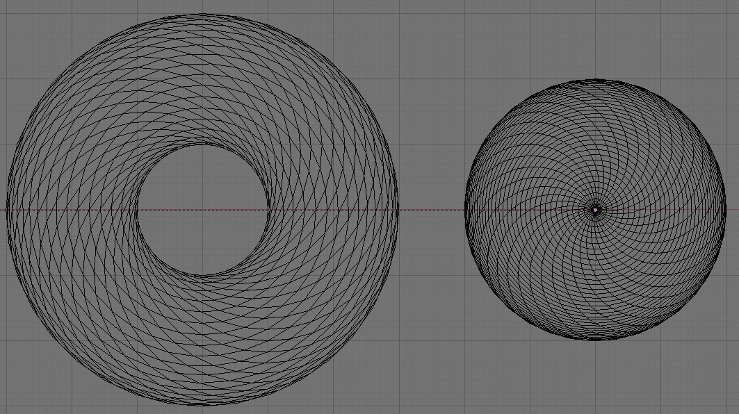
The instability happens as an intrinsic nature of the polar transform. Near (0,0), the one axis must strain to meet the motion demands. At the limit, the table must rotate thru 180 degrees as the point passes thru point (0,0). If it actually passes thru the point (0,0), you can avoid the 180 degree motion by inverting and choosing the other branch of the inverse trig functions (I.E, in ACOS solution, you choose ACOS + pi solution instead.) However, this does not work for lines tangent to a small circle near (0,0), and you therefore have to slow down you printing speed in order to allow the axis time to rotate thru the needed angle. A similar problem exists at the other limit, but in this case, you get extremely slow motion into radial line direction.
I've attached the transform from the model space into a grid where the grid lines represent constant motion on one motor. As you can see, you run into problems at the outer edges, and innermost edge or point. The sweep plane on the left represents the model space if you do not allow the extruder to attain the center point, whereas the sweep plane on the right is the model space if you do allow for that option.
UPDATE: Looking at the sweep-plane with the offset extruder, it doesn't look right. I'll look at the model I used to generate it. One set of grid lines should be completely circular, but that doesn't appear to be the case.
Edited 1 time(s). Last edit at 02/09/2010 05:51PM by BeagleFury.
|
Re: Polar Bot Team Cyberdyne February 19, 2010 03:51PM |
Registered: 14 years ago Posts: 105 |
[objects.reprap.org]
I've gone ahead and made a wiki page giving an overview of what I'm working on and my vision of the end result.
Visual aids by the end of the month is my goal.
I've gone ahead and made a wiki page giving an overview of what I'm working on and my vision of the end result.
Visual aids by the end of the month is my goal.
Sorry, only registered users may post in this forum.