RepStrippa, my plans on a multifunction 3D printer  Comments are welcome, let me know your thoughts
Posted by Gordie
|
RepStrippa, my plans on a multifunction 3D printer Comments are welcome, let me know your thoughts March 05, 2014 07:50PM |
Admin Registered: 11 years ago Posts: 954 |
Hello everyone, after two weeks of no answers I'm here to discuss with you and to present my multifunction 3D printer. I've started this topic in CNC section but no body spoke...
First of all thanks in advance for reading this and commenting; I'm an italian guy with the DIY "mindview" and with the artisan lifestyle, I like to recycle but, most important, to change people mind on recycling everything they can.
In this way I started some years ago an artist/music project with handmade musical instruments ripped off from wasted electronics stuff. I also love hardware and toys hacking (aka circuit bending).
While building up mine own instruments I find some difficulties on having some parts with the shape I wanted. Also, I'm a student and I cannot afford the costs of third parts productions. So one day I decided to build a CNC router, then I discoverred the 3D printing world and now I'm here with my ideas.
RepStrippa features:
b) With a servo motor there will be a rolling plate, for objects to be scanned. With simple internal walls as background and a photocamera, some leds to light up and a classic laser pointer.
c) First of all I'll print a Dremel mount My goal is to engrave wood, plexiglass and maybe, again maybe, Alu; I'm not pretending to mill as a CNC router, just engrave untill 5mm deepness by taking slowly more passagges, once by one. The Repstrippa will have vacuum cleaner mount to the Dremel and to the bottom/base for debris.
d) A simple 1W diode not for cutting but simply to engrave leather. With fans and exaust way for smokes. So no CO2 system here.
e) A rotary cut bit to cut paper, vinyl and leather. Paper and vinyl will stay in position thanks to strong magnets (inside printed handles). I thought about a vacuum system for holding the paper but isn't so simple...
Materials:
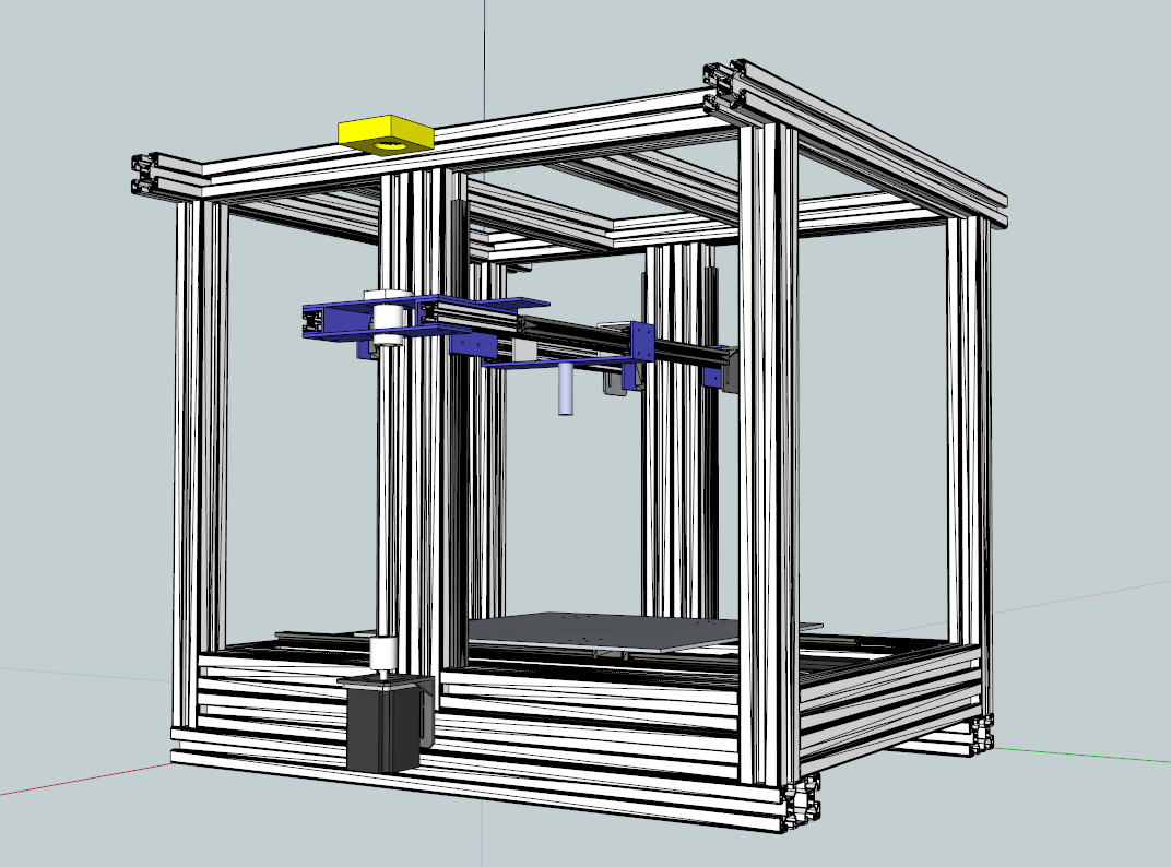
As you can see the structure is made of aluminum extrusions 40x40. There will be fasteners inside the extrusions at the corners and L plates, also 90° mounters. The overall dimensions are 750x650mm but can vary. On top the extrusions are longer because they will support the enclosure chamber. The linear guides used are IGUS Drylin T more specs here: [www.igus.com] and here: [www.igus.com]
Y AXIS: 16mm dia. 10mm step 520mm lenght ballscrew with a NEMA23 15kg.cm holding torque 3A. Alu plate 4mm. When printing: Silicone hotbed 300x300mm with cork and a 0,5 alu plate at the bottom, on top I'll experiment
Z AXIS: Two 20x20 alu extrusions are lifted by 16mm dia. 10mm step leadscrew, delrin nut. Two NEMA23 15kg.cm holding torque 3A.
X AXIS: My idea is to use two NEMA 17 6.5Kg.cm holding torque with pulleys and belts.
Electronics: I'm waiting the RAMPS-FD of bobc and I'm also in contact with an user that can give me some step drivers for the 3A demanding motors. Step drivers. I will use Udoo or Arduino Due. ImmaginaECrea extruder or the E3D. Bowden system.
From the images attached: the blue parts are the one made by a factory, they will be rectified, as the extrusions holding the linear guides. The yellow are the 3D printed by a friend of mine.
So, the main stuff has been explained, I hope you understood everything, sorry for my bad English
Another word just to say that after the printer will be ready I would like to start modelling and printing plastic parts to help building the same printer as corners and 90° angles, bushing holders and so on... Also I'm plannig (just an idea) to build this printer in a modular way so that it can be expanded along the X and Y axises only for printing, lasering and cutting NOT milling.
Here are my doubts and my questions to you mates:
Again thanks and best printings to everyone! Please ask if you have questions.
Edited 2 time(s). Last edit at 03/07/2014 02:11PM by Gordie.
First of all thanks in advance for reading this and commenting; I'm an italian guy with the DIY "mindview" and with the artisan lifestyle, I like to recycle but, most important, to change people mind on recycling everything they can.
In this way I started some years ago an artist/music project with handmade musical instruments ripped off from wasted electronics stuff. I also love hardware and toys hacking (aka circuit bending).
While building up mine own instruments I find some difficulties on having some parts with the shape I wanted. Also, I'm a student and I cannot afford the costs of third parts productions. So one day I decided to build a CNC router, then I discoverred the 3D printing world and now I'm here with my ideas.
RepStrippa features:
- 3D printing
- 3D scanning
- Dremel engraving/milling
- Laser engraving
- Paper/vinyl cutting
b) With a servo motor there will be a rolling plate, for objects to be scanned. With simple internal walls as background and a photocamera, some leds to light up and a classic laser pointer.
c) First of all I'll print a Dremel mount
My goal is to engrave wood, plexiglass and maybe, again maybe, Alu; I'm not pretending to mill as a CNC router, just engrave untill 5mm deepness by taking slowly more passagges, once by one. The Repstrippa will have vacuum cleaner mount to the Dremel and to the bottom/base for debris.d) A simple 1W diode not for cutting but simply to engrave leather. With fans and exaust way for smokes. So no CO2 system here.
e) A rotary cut bit to cut paper, vinyl and leather. Paper and vinyl will stay in position thanks to strong magnets (inside printed handles). I thought about a vacuum system for holding the paper but isn't so simple...
Materials:
As you can see the structure is made of aluminum extrusions 40x40. There will be fasteners inside the extrusions at the corners and L plates, also 90° mounters. The overall dimensions are 750x650mm but can vary. On top the extrusions are longer because they will support the enclosure chamber. The linear guides used are IGUS Drylin T more specs here: [www.igus.com] and here: [www.igus.com]
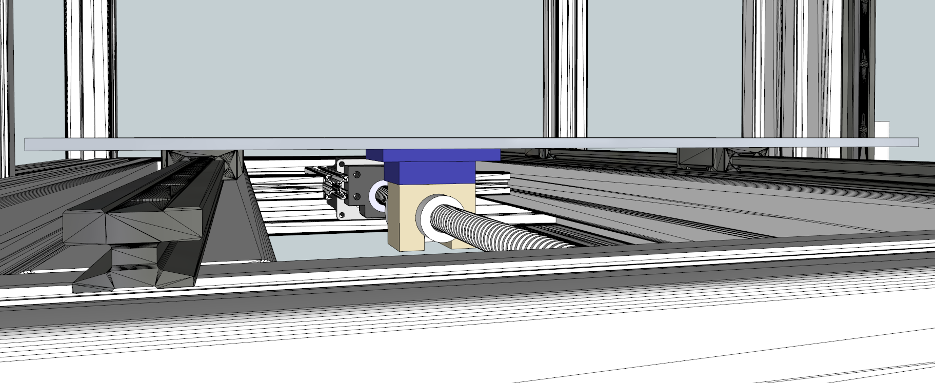
Y AXIS: 16mm dia. 10mm step 520mm lenght ballscrew with a NEMA23 15kg.cm holding torque 3A. Alu plate 4mm. When printing: Silicone hotbed 300x300mm with cork and a 0,5 alu plate at the bottom, on top I'll experiment
Z AXIS: Two 20x20 alu extrusions are lifted by 16mm dia. 10mm step leadscrew, delrin nut. Two NEMA23 15kg.cm holding torque 3A.
X AXIS: My idea is to use two NEMA 17 6.5Kg.cm holding torque with pulleys and belts.
Electronics: I'm waiting the RAMPS-FD of bobc and I'm also in contact with an user that can give me some step drivers for the 3A demanding motors. Step drivers. I will use Udoo or Arduino Due. ImmaginaECrea extruder or the E3D. Bowden system.
From the images attached: the blue parts are the one made by a factory, they will be rectified, as the extrusions holding the linear guides. The yellow are the 3D printed by a friend of mine.
So, the main stuff has been explained, I hope you understood everything, sorry for my bad English
Another word just to say that after the printer will be ready I would like to start modelling and printing plastic parts to help building the same printer as corners and 90° angles, bushing holders and so on... Also I'm plannig (just an idea) to build this printer in a modular way so that it can be expanded along the X and Y axises only for printing, lasering and cutting NOT milling.
Here are my doubts and my questions to you mates:
- Look here, at the IGUS page, they talk about floating bearings in Y and Z axises, what do you think? Shuold I use those bearings for compensate misalignment? If so where? Should I lost precision when engraving by using those floating bearing? (I know one fixed and one floating, I'm not saying "every bearing must be floating")
- What do you think about the X axis concept?
- What are your suggestions?
- More to come...
Again thanks and best printings to everyone! Please ask if you have questions.
Edited 2 time(s). Last edit at 03/07/2014 02:11PM by Gordie.
| ---- "Let me make my move" ---- |
|
Re: RepStrippa, my plans on a multifunction 3D printer Comments are welcome, let me know your thoughts March 06, 2014 12:06AM |
Admin Registered: 15 years ago Posts: 1,470 |
Always good to see new designs. I have to ask though, why is your Y axis using a screw drive while your X axis is belt-driven?
|
Help improve the RepRap wiki!
Just click "Edit" in the top-right corner of the page and start typing. Anyone can edit the wiki! |
|
Re: RepStrippa, my plans on a multifunction 3D printer Comments are welcome, let me know your thoughts March 06, 2014 08:17AM |
Admin Registered: 11 years ago Posts: 954 |
Hello NewPerfection and thx for the comment.
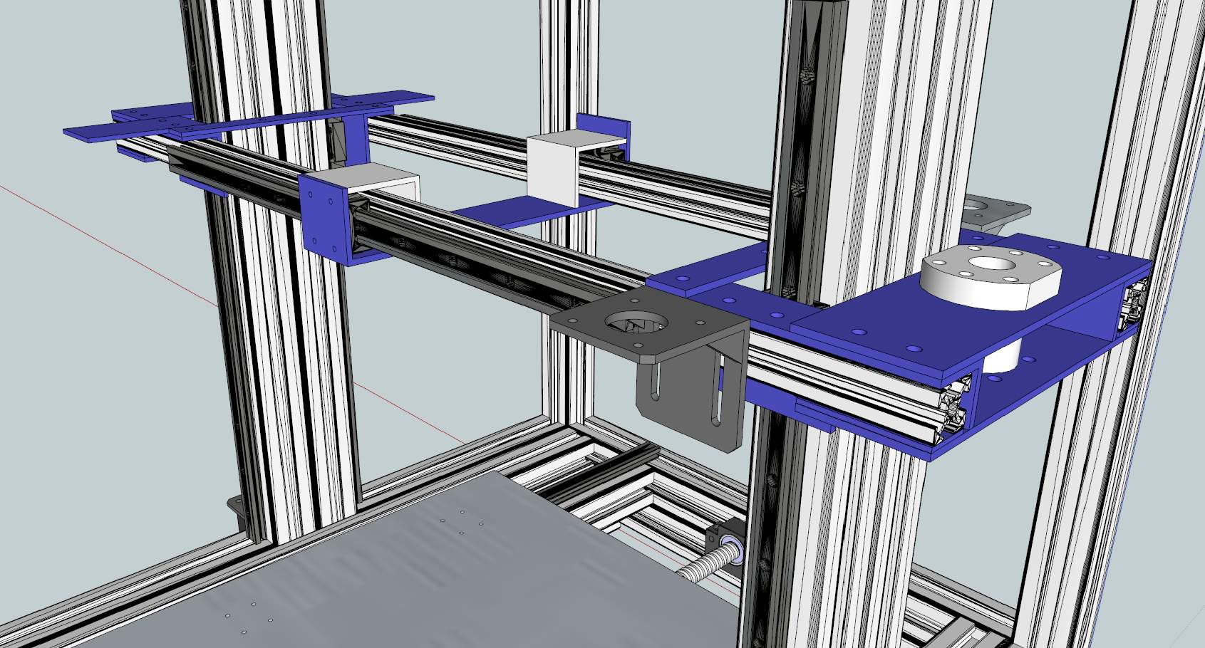
I went with belt drive on X because a screw drive was not so easy to implement. I'm not a physician but I know that the more the leadscrew is centered on the axis the more the force is; so in my design, as you can see, I use two IGUS linear rails in X axis, if I put a leadscrew in the middle of the two rails (best force) I cannot "tuoch" the extruder's carrier (the blue plate with the two white L in image Xaxis.jpg), changing extruders, hotends and most important I cannot mount the Dremel.
I thought to use the leadscrew on just one side of the X axis were you now see the NEMA mount, but I think I can get too friction on the opposite sliding IGUS carrier because on pulling and pushing there will be angular movement on the blue carrier. I hope you understand what I mean.
The solution could be two parallel leadscrews but this means adding more weight.
Maybe I'm wrong, I'm here to learn from you guys, do you think I could have calibration and precision problems by using two different driving system?
| ---- "Let me make my move" ---- |
|
Re: RepStrippa, my plans on a multifunction 3D printer Comments are welcome, let me know your thoughts March 06, 2014 09:17PM |
Admin Registered: 15 years ago Posts: 1,470 |
I can see the reason for using a belt drive on the X axis, but there's not much point in using a (likely more expensive) screw drive on the Y axis, since you will be limited in milling force by the belt-driven X, and be limited in print speed by the screw-driven Y. In other words, having the X axis driven in a different manner than the Y axis simply combines the worst characteristics of each method on your machine.
If your Y axis motor is powerful enough and can accelerate and run the Y axis at a high enough speed, it may not limit the print speed of your machine much, if at all. Even in that case I still don't see a good reason to use a screw drive instead of a belt though.
However, if you think that your Y axis will be significantly heavier than your X axis, it may very well be worth it to use a screw drive on Y in order to eliminate the "ringing" problems you can have with fast accelerations on a heavy, belt-driven axis due to the belt stretching. This could be reduced though by using steel-reinforced belts rather than fiberglass.
In other words, I don't have a definite answer as to whether the Y axis should be screw driven, but I do not think that it gives enough of an advantage (if any at all) to justify the additional cost.
I understand exactly what you mean. In the case of 3D printing, the forces are low enough that the offset drive force shouldn't be an issue. Most RepRaps drive the X axis with a belt that is attached to the carriage outside of the linear guides. However, with the forces involved in milling, this could definitely be a problem.
You mean a physicist?
If your Y axis motor is powerful enough and can accelerate and run the Y axis at a high enough speed, it may not limit the print speed of your machine much, if at all. Even in that case I still don't see a good reason to use a screw drive instead of a belt though.
However, if you think that your Y axis will be significantly heavier than your X axis, it may very well be worth it to use a screw drive on Y in order to eliminate the "ringing" problems you can have with fast accelerations on a heavy, belt-driven axis due to the belt stretching. This could be reduced though by using steel-reinforced belts rather than fiberglass.
In other words, I don't have a definite answer as to whether the Y axis should be screw driven, but I do not think that it gives enough of an advantage (if any at all) to justify the additional cost.
Quote
Gordie
I thought to use the leadscrew on just one side of the X axis were you now see the NEMA mount, but I think I can get too friction on the opposite sliding IGUS carrier because on pulling and pushing there will be angular movement on the blue carrier. I hope you understand what I mean.
I understand exactly what you mean. In the case of 3D printing, the forces are low enough that the offset drive force shouldn't be an issue. Most RepRaps drive the X axis with a belt that is attached to the carriage outside of the linear guides. However, with the forces involved in milling, this could definitely be a problem.
You mean a physicist?
|
Help improve the RepRap wiki!
Just click "Edit" in the top-right corner of the page and start typing. Anyone can edit the wiki! |
|
Re: RepStrippa, my plans on a multifunction 3D printer Comments are welcome, let me know your thoughts March 07, 2014 09:22AM |
Admin Registered: 11 years ago Posts: 954 |
Yes indeed, physicist... Ahahahah 
Thx for your quick answer, It means a lot for me after weeks of silence. Your thoughts give me the idea to use the belt on the Y axis, it cost less and if it will not work I can always put on a leadscrew. Now I've to redesign the Y axis.
I thought the leadscrew could be strong and fast enough as it has a 10mm of step travel and the NEMA 23 has 15kg.cm holding torque.
What do you think about the rest of the project? And about my question N° 1?
| ---- "Let me make my move" ---- |
|
Re: RepStrippa, my plans on a multifunction 3D printer Comments are welcome, let me know your thoughts March 07, 2014 01:27PM |
Admin Registered: 15 years ago Posts: 1,470 |
The holding torque of the stepper on the lead screw isn't of too much concern, as much as it's top speed, torque at speed, and acceleration ability. You would have a hard time driving a NEMA 23 past 1000 RPM, especially with inexpensive drivers. Plus, the torque drops off a huge amount at high speeds, especially if you are only running at 12V. 1000 RPM translates to 167 mm/s, which isn't bad if you have enough torque left at that speed to not skip steps. In the end it may very well be possible to use a screw driven Y without any detriment to print speed with proper drivers, motors, and supply voltage, but some experimentation would need to be done and I'm still not sure if it would give enough of a benefit to be worth the trouble and expense.Quote
Gordie
I thought the leadscrew could be strong and fast enough as it has a 10mm of step travel and the NEMA 23 has 15kg.cm holding torque.
The rest of the project looks nice. It would be great to have a multi-function machine that has easily changeable heads for different types of manufacturing. In fact I have been working on a design for a small CNC router that should also work as a decent, if a bit slow, 3D printer or laser engraver with the right tool heads. It's very much preliminary though and I don't have much more than a conceptual CAD model, but my intent is to make as rigid of a machine as possible using large aluminum extrusions, stiff joints, and strong linear guides. All three axes would be screw driven, and would hopefully be able to mill aluminum at a decent speed. Trying to keep the cost down is proving difficult since good lead screws and guides are expensive, although the basic frame should have a reasonable cost.Quote
Gordie
What do you think about the rest of the project?
As for question 1,
Floating bearings on one rail of each axis would be a good idea. It reduces friction, makes assembly and alignment easier, and doesn't hurt accuracy as long as the loads are reasonable. I could potentially see an increase in deflection of the axes under high load conditions versus using fixed bearings on both rails, but you are probably more limited by the belt drive in that regard anyways.Quote
Gordie
Look here, at the IGUS page, they talk about floating bearings in Y and Z axises, what do you think? Shuold I use those bearings for compensate misalignment? If so where? Should I lost precision when engraving by using those floating bearing? (I know one fixed and one floating, I'm not saying "every bearing must be floating")
I think that most RepRaps don't use floating bearings just because it's easier and cheaper to use linear bearings on smooth rod, and AFAIK there doesn't exist a floating linear ball bearing for round rod. There does exist linear bearings that can compensate for angular misalignment, but they can't compensate for rods that aren't parallel, and I don't think you can get them as cheaply as the Chinese bearings that most people use. Plus the forces involved in 3D printing tend to be low, so a slight decrease in the life of the linear bearings isn't too big of a deal, especially since they are so cheap.
The original Mendel design did use "floating" bearings on the X and Y axis, but it was a much more complicated setup using ball bearings.
Edited 1 time(s). Last edit at 03/07/2014 01:29PM by NewPerfection.
|
Help improve the RepRap wiki!
Just click "Edit" in the top-right corner of the page and start typing. Anyone can edit the wiki! |
|
Re: RepStrippa, my plans on a multifunction 3D printer Comments are welcome, let me know your thoughts March 07, 2014 02:05PM |
Admin Registered: 11 years ago Posts: 954 |
Again thanks Cameron, great answering.
For the step motor, this is mine NEMA 23: [www.goodluckbuy.com]
And for the step driver I will use this: [www.massmind.org]
Just to add more info (I will edit my first post).
For the floating bearings, thanks for your explanation, so I think I will go with them. Those IGUS are not so expensive, the real problems are the floating bearings, they cost each 14€+VAT and I need 10 of them... The total actually is 380€ VAT included. But those linear bearings are very good 15m/s!
I'm curious to see your plans
| ---- "Let me make my move" ---- |
|
Re: RepStrippa, my plans on a multifunction 3D printer Comments are welcome, let me know your thoughts March 07, 2014 03:41PM |
Admin Registered: 15 years ago Posts: 1,470 |
I can't seem to find a data sheet for that particular motor, but many stepper motors loose as much as 90% of their torque as they approach higher speeds. This may be ok though since 3D printing doesn't require large forces (as long as your Y axis isn't too heavy), and for milling you won't be moving nearly as fast.
That stepper driver looks really nice. I like that it will work with Marlin as-is, since most stepper drivers won't. Plus it's reasonably priced for it's capabilities, though I think most RepRappers would be scared away by the fact that it costs 2x - 3x as much as a Pololu-type driver. It's perfect for a larger machine though.
Here's a render of my design as it stands, although I haven't put too much thought into it for a while:
It would utilize a moving bed rather than the moving gantry that is popular on low-cost CNC routers. This reduces build volume compared to the size of the machine, but allows for increased rigidity and accuracy.
That stepper driver looks really nice. I like that it will work with Marlin as-is, since most stepper drivers won't. Plus it's reasonably priced for it's capabilities, though I think most RepRappers would be scared away by the fact that it costs 2x - 3x as much as a Pololu-type driver. It's perfect for a larger machine though.
Here's a render of my design as it stands, although I haven't put too much thought into it for a while:

It would utilize a moving bed rather than the moving gantry that is popular on low-cost CNC routers. This reduces build volume compared to the size of the machine, but allows for increased rigidity and accuracy.
|
Help improve the RepRap wiki!
Just click "Edit" in the top-right corner of the page and start typing. Anyone can edit the wiki! |
|
Re: RepStrippa, my plans on a multifunction 3D printer Comments are welcome, let me know your thoughts March 08, 2014 09:13AM |
Admin Registered: 11 years ago Posts: 954 |
Hi, yes your moving bed allows for increased rigidity and accuracy, but what about X axis? Has your machine only the bed moving?
I really like your render, what software did you use?
About my motors, I found this which seems the manifacturer but I'm not so sure: [www.shengyangmotor.com]
I found also this which seems better "manifacturer": [www.kysanelectronics.com]
The real problem? On one page they say they are bipolar, on the other they say they are unipolar. I'll investigate with the meter.
And that step driver is nearly perfect.
Edit: I forgot to ask you, what kind of belt do you suggest for mine Y,X Axis? GT2?
Edited 5 time(s). Last edit at 03/08/2014 08:49PM by Gordie.
| ---- "Let me make my move" ---- |
|
Re: RepStrippa, my plans on a multifunction 3D printer Comments are welcome, let me know your thoughts March 10, 2014 05:19PM |
Admin Registered: 15 years ago Posts: 1,470 |
The X axis would be a moving carriage attached to rails that run along the upper horizontal extrusions.Quote
Gordie
Hi, yes your moving bed allows for increased rigidity and accuracy, but what about X axis? Has your machine only the bed moving?
SolidWorks.Quote
Gordie
I really like your render, what software did you use?
There's some discussion on whether GT2 is better than T2.5 for linear motion. GT2 supposedly has a better tooth profile for reducing backlash, but I have doubts that it makes a significant difference versus using a proper pulley with T2.5. GT2 is also typically fiberglass-reinforced, where T2.5 is steel-reinforced. T2.5 will therefore be stiffer, but as a consequence cannot bend as tightly as GT2 (resulting in a larger minimum pulley diameter).Quote
Gordie
Edit: I forgot to ask you, what kind of belt do you suggest for mine Y,X Axis? GT2?
|
Help improve the RepRap wiki!
Just click "Edit" in the top-right corner of the page and start typing. Anyone can edit the wiki! |
|
Re: RepStrippa, my plans on a multifunction 3D printer Comments are welcome, let me know your thoughts March 23, 2014 03:29PM |
Admin Registered: 11 years ago Posts: 954 |
Hi, just a quick update. I found out from my readings that the ATL belts can be the right choice for my X axis. The one I'll go is ATL5 25mm width. I'll keep other updates as soon as my project go on. Atm I'm studing about earthing and noise issues. Thanks Cameron.
Atm I'm studing about earthing and noise issues. Thanks Cameron.| ---- "Let me make my move" ---- |
|
Re: RepStrippa, my plans on a multifunction 3D printer Comments are welcome, let me know your thoughts March 26, 2014 10:51AM |
Registered: 10 years ago Posts: 75 |
Gordie,
When deciding the belt, just be sure you take into account that probably the smallest pulley you can get with a GT2 will still not limit your max speed... so basically, the smaller the better for max torque, unless at some point it limits your max speed. I did some math in this post.
When deciding the belt, just be sure you take into account that probably the smallest pulley you can get with a GT2 will still not limit your max speed... so basically, the smaller the better for max torque, unless at some point it limits your max speed. I did some math in this post.
|
Re: RepStrippa, my plans on a multifunction 3D printer Comments are welcome, let me know your thoughts April 01, 2014 10:42PM |
Registered: 10 years ago Posts: 17 |
I'm about 2/3 of the way through something similar to what Gordie proposes and Tired2 is doing (I have similar motivations as Gordie wrote).
A thought I had recently, while trying to hand make parts to get the printer up and running so I can print the final parts is this:
Doing a nice job of a combo printer/light mill would have been a lot easier if I had a small decent quality 3D printer.
So, Chaucer caught my eye as a good start for such a thing.
A good use case is to print threadless ball screws, so I wouldn't have had to buy 1204 ball screws from ebay. In addition, mounting the motors, linear motion stuff, and so on, would have been a lot easier.
I think designing a combo printer/light mill using such parts and an existing small printer would result in much lower cost.
I'll attach an image of my design using ballscrews - the openscad files are a work in progress, and were intended to show proof of concept to me, so do not look finished. I really do like the U-groove ball bearings on ground steel rods - that part I think worked out really well. My base is 3/4 inch Mic 6 aluminum plate.
My printer is shown with 1605 ballscrews, which are way too big, I bought 1204 instead. I have nema 23 steppers, arduino due, and ramps-fd sitting on my lap as I type this. Hoping to get it working at 24 volts, although I originally wanted to run 36, but the ramps-fd has 35 volt capacitors on it. I do have one massmind stepper controller, and I may wire a pair of those into the ramps-fd board and use higher voltage for the X and Y axes. The Z axis is not performance critical for 3D printing.
Paul
A thought I had recently, while trying to hand make parts to get the printer up and running so I can print the final parts is this:
Doing a nice job of a combo printer/light mill would have been a lot easier if I had a small decent quality 3D printer.
So, Chaucer caught my eye as a good start for such a thing.
A good use case is to print threadless ball screws, so I wouldn't have had to buy 1204 ball screws from ebay. In addition, mounting the motors, linear motion stuff, and so on, would have been a lot easier.
I think designing a combo printer/light mill using such parts and an existing small printer would result in much lower cost.
I'll attach an image of my design using ballscrews - the openscad files are a work in progress, and were intended to show proof of concept to me, so do not look finished. I really do like the U-groove ball bearings on ground steel rods - that part I think worked out really well. My base is 3/4 inch Mic 6 aluminum plate.
My printer is shown with 1605 ballscrews, which are way too big, I bought 1204 instead. I have nema 23 steppers, arduino due, and ramps-fd sitting on my lap as I type this. Hoping to get it working at 24 volts, although I originally wanted to run 36, but the ramps-fd has 35 volt capacitors on it. I do have one massmind stepper controller, and I may wire a pair of those into the ramps-fd board and use higher voltage for the X and Y axes. The Z axis is not performance critical for 3D printing.

Paul
|
Re: RepStrippa, my plans on a multifunction 3D printer Comments are welcome, let me know your thoughts April 01, 2014 11:39PM |
Registered: 10 years ago Posts: 474 |
Now that is a shame you didn't research a little bit more on using ballscrews for printer I'm a big advocate of using them but the ones you chose are absolutely no good. At 4 mm per turn it's going to be the slowest 3-D printer ever made you need at least 16mm per turn and preferably 20 mm or above per turn to reach printing speeds. And as a mill it is also terrible nowhere near strong enough about the only thing you possibly could do is mill a circuitboard balsa or StyrofoamQuote
powool
I'm about 2/3 of the way through something similar to what Gordie proposes and Tired2 is doing (I have similar motivations as Gordie wrote).
A thought I had recently, while trying to hand make parts to get the printer up and running so I can print the final parts is this:
Doing a nice job of a combo printer/light mill would have been a lot easier if I had a small decent quality 3D printer.
So, Chaucer caught my eye as a good start for such a thing.
A good use case is to print threadless ball screws, so I wouldn't have had to buy 1204 ball screws from ebay. In addition, mounting the motors, linear motion stuff, and so on, would have been a lot easier.
I think designing a combo printer/light mill using such parts and an existing small printer would result in much lower cost.
I'll attach an image of my design using ballscrews - the openscad files are a work in progress, and were intended to show proof of concept to me, so do not look finished. I really do like the U-groove ball bearings on ground steel rods - that part I think worked out really well. My base is 3/4 inch Mic 6 aluminum plate.
My printer [attachment 29855 printer2.png] is shown with 1605 ballscrews, which are way too big, I bought 1204 instead. I have nema 23 steppers, arduino due, and ramps-fd sitting on my lap as I type this. Hoping to get it working at 24 volts, although I originally wanted to run 36, but the ramps-fd has 35 volt capacitors on it. I do have one massmind stepper controller, and I may wire a pair of those into the ramps-fd board and use higher voltage for the X and Y axes. The Z axis is not performance critical for 3D printing.
Paul
Edited 1 time(s). Last edit at 04/01/2014 11:51PM by cnc dick.
|
Re: RepStrippa, my plans on a multifunction 3D printer Comments are welcome, let me know your thoughts April 02, 2014 08:02AM |
Registered: 10 years ago Posts: 17 |
Quote
cnc dick
Now that is a shame you didn't research a little bit more on using ballscrews for printer I'm a big advocate of using them but the ones you chose are absolutely no good. At 4 mm per turn it's going to be the slowest 3-D printer ever made you need at least 16mm per turn and preferably 20 mm or above per turn to reach printing speeds. And as a mill it is also terrible nowhere near strong enough about the only thing you possibly could do is mill a circuitboard balsa or Styrofoam
I did research it quite a bit, actually - to make use of the slow ball screws, I need fast steppers. Currently, I'm trying low inductance nema 23 lin engineering ones that were the highest speed "cheap" ones I could get - the ones I want are around $100 each, so for now, I bought a set of five slower ones for about that amount.
To get the step rate up, I'm starting with the massmind stepper controller on the X and Y axis where it counts, and setting up an arm based controller, to increase the step rate past what an AVR can do. I'll use geckos running at 48 volts or more if I need to in order to get the step rate up. The motors can handle it, it's a question of good control.
It will be within reach to get somewhere in the 50-75mm per second range with my steppers and these ballscrews, which is my minimum goal for 3D printing with this printer.
As to milling - the state of the current build is using a 40mm x 20mm extrusion for the X axis carriage, which isn't rigid enough for anything to speak of. I'm pretty confident that the base (.75" cast aluminum) and frame can take the stress of a small motor (maybe only dremel or a colt) and do the basic things I want to do in aluminum (precise holes, PCB milling).
The compromises I'm willing to make are different than most - partly because I see this as an evolutionary design - for example, once it can print precision 3D objects (albeit slowly), I can print my own ballscrews (the threadless ones), better braces and so on.
I'm having a lot of fun with it, which is the main thing...
Paul
|
Re: RepStrippa, my plans on a multifunction 3D printer Comments are welcome, let me know your thoughts April 02, 2014 09:50AM |
Registered: 10 years ago Posts: 474 |
|
Re: RepStrippa, my plans on a multifunction 3D printer Comments are welcome, let me know your thoughts April 07, 2014 04:24AM |
Admin Registered: 11 years ago Posts: 954 |
powol: Thanks for showing your project, you said the right thing "I'm having a lot of fun with it, which is the main thing... "  . Keep us updated maybe opening a new topic, as you've read my first was using ballscrews so I really want to see your progress.
cnc dick: Ehi nice to have you in my topic, I've read a lot of your posts here; what are your suggestions about my project since you've a lot of experience on both field (cnc and 3d printing)? Thx
. Keep us updated maybe opening a new topic, as you've read my first was using ballscrews so I really want to see your progress.cnc dick: Ehi nice to have you in my topic, I've read a lot of your posts here; what are your suggestions about my project since you've a lot of experience on both field (cnc and 3d printing)? Thx
| ---- "Let me make my move" ---- |
|
Re: RepStrippa, my plans on a multifunction 3D printer Comments are welcome, let me know your thoughts July 14, 2014 08:49AM |
Registered: 10 years ago Posts: 1,381 |
I like your project, can you give us an update of your thoughts, and progress.
I'm not a fan of applying plain plastic bearings to all axis for this machine some is OK, (below I explain more). I think the start-up friction (a minimal concern), and the low bearing preload (more importantly) is not ideal for milling, it's OK for filament printing.
It's OK to over constrain your bearings if you are subjecting them to shock, and you have the torque to move the mass (2X the estimated is recommended, but is difficult to achieve, cost go up fast), and can reasonably align them, and have a frame that doesn't flex or shift. It's a pita if you have a floating bearing rail that vibrates when you are milling.
Inexpensive supported linear shaft bearing made from steel would be a significant improvement, this seller has some examples for you to consider: [stores.ebay.com], I have not purchased from them, just for an example.
Add as many 45 degree plates that you can afford to help maintain alignment, and to resist bending forces to each structural member. If you can't afford metal, use 45 degree wood braces, (walnut, oak, ash with metal inserts to distribute the load). Paint, or epoxy coat the wood to minimize dimensional changes due to moisture.
X-axis (fixed gantry) is always a challenge, it's a compromise to create a ridged, load bearing, and dampening proof design. Take a look at CNC routers for examples, and think of the forces that you will encounter that will compromise precision. Most place the bearings vertically aligned, you have yours horizontally aligned. If your machine is ridged, doesn't flex under load, and the forces accounted for it wont matter. It's nice to have a center space to place modular tooling, so I think your OK with your choice. If you have concerns with the X-axis design, create a box structure of the X-axis. That would entail adding additional bearings to the Z-axis. You can use a mixture of bearings on the X-axis, one rail igus, the other metal. Dampening from the igus will be beneficial in some circumstances.
Tks!
Quote
Gordie
(The linear guides used are IGUS Drylin T more specs here: [www.igus.com] and here: [www.igus.com]
I'm not a fan of applying plain plastic bearings to all axis for this machine some is OK, (below I explain more). I think the start-up friction (a minimal concern), and the low bearing preload (more importantly) is not ideal for milling, it's OK for filament printing.
Quote
Gordie
Look here, at the IGUS page, they talk about floating bearings in Y and Z axises, what do you think? Shuold I use those bearings for compensate misalignment? If so where? Should I lost precision when engraving by using those floating bearing? (I know one fixed and one floating, I'm not saying "every bearing must be floating")
It's OK to over constrain your bearings if you are subjecting them to shock, and you have the torque to move the mass (2X the estimated is recommended, but is difficult to achieve, cost go up fast), and can reasonably align them, and have a frame that doesn't flex or shift. It's a pita if you have a floating bearing rail that vibrates when you are milling.
Inexpensive supported linear shaft bearing made from steel would be a significant improvement, this seller has some examples for you to consider: [stores.ebay.com], I have not purchased from them, just for an example.
Add as many 45 degree plates that you can afford to help maintain alignment, and to resist bending forces to each structural member. If you can't afford metal, use 45 degree wood braces, (walnut, oak, ash with metal inserts to distribute the load). Paint, or epoxy coat the wood to minimize dimensional changes due to moisture.
Quote
Gordie
What do you think about the X axis concept?
X-axis (fixed gantry) is always a challenge, it's a compromise to create a ridged, load bearing, and dampening proof design. Take a look at CNC routers for examples, and think of the forces that you will encounter that will compromise precision. Most place the bearings vertically aligned, you have yours horizontally aligned. If your machine is ridged, doesn't flex under load, and the forces accounted for it wont matter. It's nice to have a center space to place modular tooling, so I think your OK with your choice. If you have concerns with the X-axis design, create a box structure of the X-axis. That would entail adding additional bearings to the Z-axis. You can use a mixture of bearings on the X-axis, one rail igus, the other metal. Dampening from the igus will be beneficial in some circumstances.
Tks!
|
Re: RepStrippa, my plans on a multifunction 3D printer Comments are welcome, let me know your thoughts July 16, 2014 06:07AM |
Admin Registered: 11 years ago Posts: 954 |
Hi A2 and thanks!
ATM I'm stucked on a simple word, money... I'm collecting money to build my project so now I'm in halt mode. The Igus Drylin total cost rise up to 400€ and the total cost of the project could be something like 1500€. Money that I don't have...
Maybe I'll open a Kickstarter founding ahahahahahah
Btw, maybe I could think about using the linear shaft bearings for the Y axis, for Z and X I would keep those Igus. I'm interested on your thoughts about low bearing preload, are you talking about these Igus Drylin? Please explain.
About milling, I just want to engrave not mill, just engrave with a max depth of 5mm; I understand what you're talking about and I'm also considering:
- Look at the X axis, it has two extruded profiles where the "printhead" moves. I was thinking to add another profile when using the printer as engraver; on one side, above the existing X's profiles with two Igus carriers and fixed to the "main" X profiles by some steel. I think it could be a good solution, also it will keep calibration since the Igus carriers will be fixed by 8 screws. In fact, when I'll need to engrave I will do just few steps, lower the X axis, insert the profile to the Igus guides (the two on Z axis), attach the profile to the main X with some steel, attach the Dremel/drill/mill mount to the "new" X axis.
It will transform the printer to a classic style router.
But this is just an idea, when I'll have all the materials in my hand I could be more sure on what to do.
| ---- "Let me make my move" ---- |
|
Re: RepStrippa, my plans on a multifunction 3D printer Comments are welcome, let me know your thoughts July 16, 2014 07:08AM |
Registered: 10 years ago Posts: 1,381 |
Your igus bearing cost estimate of 400€ looks about right. I've seen filament printers used for light Dremel routeing with no special modifications, other than using high torque steppers.
Take a look at the Chinease supported linear rails Dia 12mm x 500mm long, $70.00 usd for a pair, x 3 = $210.00 + tax, might be the lowest cost?
2pcs SBR12-500mm 12MM SUPPORTED LINEAR RAIL SLIDE SHAFT + 4pcs SBR12UU Blocks
[www.ebay.com]
Another option is the Openbuilds 20x80 V-slots, but I think you need to see if you can reduce the V-wheel bearing cost. A large expense with Openbuilds are the wheels, and brackets, if you can figure out how to make your own you could save a lot of money. Take a look at how Shapeoko routers are assembled for alternative ideas.
shapeoko
[www.shapeoko.com]
Openbuilds,
[openbuildspartstore.com]
Take a look at the contraptor for bearing ideas
[www.contraptor.org]
Edited 1 time(s). Last edit at 07/16/2014 08:36AM by A2.
|
Re: RepStrippa, my plans on a multifunction 3D printer Comments are welcome, let me know your thoughts August 25, 2014 07:02PM |
Registered: 9 years ago Posts: 2 |
The idea of a multifunction machine is good. Just found this one coming next month. Fabtotum Will be interesting to see how well it works.
On paper/vinyl cutting, there are numerous 2d electronic cutting machines on the market all using small knives to produce very detailed cuts - loads of reviews online.
The one I found about first was this all-in-one scanner and cutter Brother Scan N Cut. Have been wondering about getting one of those type of electronic cutting machines. This one is on my short list - Zing Air.
I've been looking at the commercially available linear drives with ball screws to see what is available.For example THK low price actuator
While these will cost more than belt drive, they should provide the strength and precision required for multi=purpose use.
The other thing I saw is CubeSpawn - modular micro factory which has separate units to do each process.
Edited 1 time(s). Last edit at 08/25/2014 07:48PM by blueytoo.
Sorry, only registered users may post in this forum.