Connecting extruded aluminium?
Posted by Treito
|
Re: Connecting extruded aluminium? December 31, 2015 11:19AM |
Registered: 9 years ago Posts: 893 |
Welding has one major problem - distortion caused by heat and the contraction of the metal. How do I know?
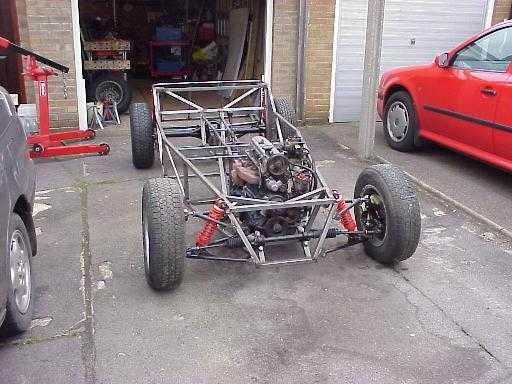
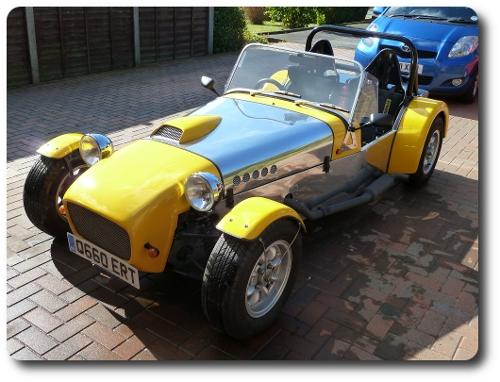
I built this chassis from a heap of square-section steel tube on the garage floor - so I'm very aware that welding is a constant struggle to manage distortion as you move around the work, trying to counteract one piece of warping with that caused by another weld.
I would *not* wish to weld something as small as a 3D printer, knowing that accuracy is everything. Accuracy just won't happen.
|
Re: Connecting extruded aluminium? December 31, 2015 12:02PM |
Registered: 11 years ago Posts: 5,780 |
Such distortion only matters if you're trying to use the frame as the reference for the alignment of the axes. Many printer designs do just that (including my own, to some extent), but it doesn't have to be that way. The frame can be just a rigid frame in which to mount parts that are made alignable independent of it, and something to enclose the machine.
Ultra MegaMax Dominator 3D printer: [drmrehorst.blogspot.com]
Ultra MegaMax Dominator 3D printer: [drmrehorst.blogspot.com]
|
Re: Connecting extruded aluminium? December 31, 2015 12:41PM |
Registered: 9 years ago Posts: 1,699 |
Anybody who is able to buy and mount a kit should be able to reproduce my printer and it should give a good quality of course. The intention is meant for my use only, but I have some new ideas which I will test and I will provide. What would be making me more proud of my design if anybody copies parts of it or somebody rebuild the whole printer? I designed some parts for my Ormerod 2 intended for my use only but I provided the design on thingiverse. Before I was able to print it and test it by myself I got feedback from one person who used my design successfully. That was a really good feeling especially as it was a problematic design regarding stability.Quote
the_digital_dentist
Quote
Treito
I have no welding equipment and the welding was some sort of joke, but this would have been the stablest variant. The second problem is that it should be of course some sort of RepRap printer so easily to recreate.
Ah, philosophy! Philosophy is like a bag of bricks you carry around everywhere you go. Who are you carrying it for? Why not just set it down?
In your philosophy, what is the definition of "easy" and to whom does it apply? Someone with welding equipment can easily recreate a welded frame, a quadriplegic can't. Are you planning to go into production or building a printer for your own use? How does this philosophical ideal rank among the numerous constraints you're putting on this project? Philosophy and quality are in direct opposition to each other- the more 3D printer reproducible the machine is- i.e the more printed content a printer has- the less likely it is to produce quality parts. Maybe your philosophy can be interpreted in a way that will allow you to proceed. Maybe it's OK if the printer can't reproduce itself but can produce high quality parts for other printer designs. Wouldn't it be better, philosophically speaking, to be able to produce very high quality parts so that the printers made from those parts work well, or is the philosophy only about quantity, not quality?
The computer magazine publisher did not see any differences between a closed chamber or open frame. I also can print with my printer nearly warp-free (between 0.0 and 0.1mm). The print surface is also important. Okay I may have some fail prints but I bet that you will have them with a chamber, too. And I nearly found settings which are good to use so that there is no warping. I even managed a hardly to print part warp-free where even PLA was warping. But my Idea was to find a design which can be extended to a chamber somehow, but at the moment I do not see a really need for this.Quote
Quote
Treito
2) Is out of race. It would not make me happy looking at it. Besides that a German computer magazine publisher (Heise) tested closed chambers versus open chambers and they did not notice any differences. Unfortunately it was an internal test only so it was mentioned only with one sentence in an article. I would more prefer a design more like snappy even though it is not a CoreXY and I would always use GT2 belts. But it would be more expensive and more loud than Aluminium extrusions.
It doesn't matter what you use to make the frame, if you intend to print with ABS you will need a closed build chamber. The chamber must be a warm 45-50C, or ABS prints will warp and delaminate. That means you should put the electronics outside the build chamber, so unlike most designs where positioning the electronics and cables are an afterthought, you should plan the location in advance and design the frame to include warm and cool zones, and design it for easy access to the electronics for maintenance and repairs.
It was meant as problem during the mounting. If the screws are tight the extrusion will not twist, but especially while putting them tight the extrusion may rotate or I am afraid of this. It seems that you got other experience in this way.Quote
Quote
Treito
4) and 5) Disadvantage: You may twist the extrusion
Yes, a single screw butt joint can allow the frame pieces to rotate unless there is something attached to them that prevents rotation. That is how my printer is built. Once the screws are tightened down it is very difficult to rotate any of the frame pieces. In the two years my original printer was in use the screws never loosened and none of the frame pieces ever rotated. The machine has been in its current form for a year without any rotation. There are no rotational forces applied, so the pieces don't rotate. Look at it this way- there's nothing to prevent a screw and nut from rotating either, yet without tools it is very difficult to get them to rotate. The frame piece receiving the screw is a nut.
My bed support of the Ormerod 2 is printed with PLA. There is no problem so far. Okay there is a distance between it and the bed because of the leveling. But as long as you have a good insulation there should not be a big problem. I used another design for my Ormerod 1 for a time and after I dismounted it there were no damages to the plastic.Quote
Quote
Treito
1) Maybe for smaller areas like the heated bed carriage. At a Facebook group I nearly got killed as they told me as I considered this idea. It would not be precisely enough as no printer prints 90° perfectly and it would be too weak. Even if I print a dice? You could directly print connectors onto it so it should not be weak, should it?
I would avoid putting any printed parts anywhere near the bed plate. Printed corners are not as strong, rigid, or reliable as metal to metal attachment, and they don't look very nice, but they may be strong, rigid, and reliable enough. People have successfully built printers with them. Printing corner cubes could work, but how is butting aluminum to a piece of plastic better than butting aluminum to aluminum? I milled the ends of the frame pieces square so the butt joints in my frame needed no shims. Whether you're butting aluminum to aluminum or to plastic, you may have to shim the joint to make it square, depending on how square the aluminum is cut and how square the plastic is printed.
That would be of course an option, but not that precise. It may only work as addition.Quote
Quote
Treito
Even if the plate only costs 5.34€, why is it still so expensive? 1 meter extrusions needs more material and costs only half of the price. Okay it is of course another production process but in my eyes it is not more worth than 3€. I guess the margin of the extrusion is not much and the money comes back with the help of the additional parts needed like inkjet printers.
Aluminum plate is cheap and so is a drill bit. You can easily make the flat plate connectors with a saw and a hand drill. Then you attach the plates to the frame using carriage bolts. It's a lot of hardware, but it's pretty cheap, and pretty easy. If the screw holes in the plate are slightly oversized, there will be enough slop that you'll easily be able to make the joint square.
So at the moment I got stuck with my design as I am still not sure which extrusion I should use. Welding is no option. I am not that good in welding and I have welded parts together several years ago. Besides that I do not believe that you can weld something together precisely enough and it also would not look good or you will have to do much treatment afterwards which may affect my ideas in a negative way.
Edited 1 time(s). Last edit at 12/31/2015 12:42PM by Treito.
Slicer: Simplify3D 4.0; sometimes CraftWare 1.14 or Cura 2.7
Delta with Duet-WiFi, FW: 1.20.1RC2; mini-sensor board by dc42 for auto-leveling
Ormerod common modifications: Mini-sensor board by dc42, aluminum X-arm, 0.4 mm nozzle E3D like, 2nd fan, Z stepper nut M5 x 15, Herringbone gears, Z-axis bearing at top, spring loaded extruder with pneumatic fitting, Y belt axis tensioner
Ormerod 2: FW: 1.19-dc42 on Duet-WiFi. own build, modifications: GT2-belts, silicone heat-bed, different motors and so on. Printed parts: bed support, (PSU holder) and Y-feet.
Ormerod 1: FW: 1.15c-dc42 on 1k Duet-Board. Modifications: Aluminium bed-support, (nearly) all parts reprinted in PLA/ ABS, and so on.
|
Re: Connecting extruded aluminium? December 31, 2015 01:10PM |
Registered: 9 years ago Posts: 893 |
Quote
the_digital_dentist
Such distortion only matters if you're trying to use the frame as the reference for the alignment of the axes. Many printer designs do just that (including my own, to some extent), but it doesn't have to be that way. The frame can be just a rigid frame in which to mount parts that are made alignable independent of it, and something to enclose the machine.
There are ways of welding that minimise distortion - spot welding comes to mind - but the OP was looking for an economical way of producing a frame, and spot welders are expensive!
|
Re: Connecting extruded aluminium? December 31, 2015 07:10PM |
Registered: 11 years ago Posts: 5,780 |
Quote
Treito
Anybody who is able to buy and mount a kit should be able to reproduce my printer and it should give a good quality of course. The intention is meant for my use only, but I have some new ideas which I will test and I will provide. What would be making me more proud of my design if anybody copies parts of it or somebody rebuild the whole printer? I designed some parts for my Ormerod 2 intended for my use only but I provided the design on thingiverse. Before I was able to print it and test it by myself I got feedback from one person who used my design successfully. That was a really good feeling especially as it was a problematic design regarding stability.
I think you're being generous to a fault to worry about other people being able to copy your design as cheaply as possible, even to the extent that you will avoid some really good options for its construction. I think you should focus on what you want the printer to be able to do, and if others like it, they can do whatever it takes to copy it. Almost everyone (99.9%) who sets out to design a cheap and high quality printer ends up with just a cheap printer because designing for high quality takes four things that are in short supply- common sense, some understanding of technical issues, hard work, and money.
That's OK because many people who buy printers and kits also lack some or all of those four things. There are about a million different designs out there that focus on doing things as cheaply as possible, most of which are unreliable and produce prints of limited quality. You're much more likely to come up with something new and unique in the quality and reliability space than in the cheapness space- almost no one has tried. There isn't much that hasn't already been done to make printers as cheap as possible. Yours will probably end up as just one more cheap printer design among thousands.
Regarding Thingiverse, I know you have good intentions, but I think it's a bad idea to post things before you have had a chance to print and test them. I generally avoid anything on Thingiverse that isn't accompanied by a photo of the printed part because I see a lot of bad, sometimes unprintable designs posted by well intentioned noobs who don't really know what they are doing. With a single exception for an extremely simple part, I have printed and tested every design I have posted to Thingiverse and Youmagine. I like to produce quality information as well as quality prints.
Edited 2 time(s). Last edit at 01/02/2016 09:27AM by the_digital_dentist.
Ultra MegaMax Dominator 3D printer: [drmrehorst.blogspot.com]
|
Re: Connecting extruded aluminium? December 31, 2015 07:37PM |
Registered: 9 years ago Posts: 1,699 |
I placed a warning at thingiverse that the part was not tested. It was also meant to be discussed as I published on thingiverse. It were parts for my unfortunately still not yet completed task of reprapping an Ormerod 2, because some parts are only available as kit.
And you still got my intention wrong. I do not wnat to produce the cheapest of the cheapest printers. But I also do not want to produce a very expensive printer. And sorry if I am repeating myself, but I have no welding equipment and the frame only should not costs more than anything else. But I am also not the best person in doing mechanics or to be more precisely I am more the theoretical person than the practical one. So I want to keep it simple also for me. But I have worked as worker for many years so I know how to use a drill machine for example. It is not that bad.
To be honest I have considered to print the pulleys for example and use a MXL belt like my Ormerods to have more spare parts, but I soon got rid of that idea, so I will use only GT2 belts and original aluminium pulleys. Other designs uses even no belts (okay the classical Cartesian variant of course). Using a GT2 belt instead of a MXL belt is a simple strategy to improve the printing quality just a little bit, but the sum of these little bits is what counts at least.
I would like to get the best possible option for a printer with costs of less than 700€. That is my intention and I want to beat the quality and mainly the speed of my Ormerods. As I rebuild the Ormerod 2 I was wondering why somebody could have constructed this as it was. Complicated and could easily causes trouble even though it is working. Of course such an Ormerod still looks much better than a Mendel90, but good looking is not all, so I had to replace many parts.
So I want a simple and good functional design which should be at least cost effective. A frame construction that costs alone 200€ is not cost effective this is simply overdid in my eyes unless the printer is worth more than 2000€ without working time, material costs only.
Slicer: Simplify3D 4.0; sometimes CraftWare 1.14 or Cura 2.7
Delta with Duet-WiFi, FW: 1.20.1RC2; mini-sensor board by dc42 for auto-leveling
Ormerod common modifications: Mini-sensor board by dc42, aluminum X-arm, 0.4 mm nozzle E3D like, 2nd fan, Z stepper nut M5 x 15, Herringbone gears, Z-axis bearing at top, spring loaded extruder with pneumatic fitting, Y belt axis tensioner
Ormerod 2: FW: 1.19-dc42 on Duet-WiFi. own build, modifications: GT2-belts, silicone heat-bed, different motors and so on. Printed parts: bed support, (PSU holder) and Y-feet.
Ormerod 1: FW: 1.15c-dc42 on 1k Duet-Board. Modifications: Aluminium bed-support, (nearly) all parts reprinted in PLA/ ABS, and so on.
|
Re: Connecting extruded aluminium? January 02, 2016 09:01AM |
Registered: 10 years ago Posts: 553 |
Quote
TreitoIt was meant as problem during the mounting. If the screws are tight the extrusion will not twist, but especially while putting them tight the extrusion may rotate or I am afraid of this. It seems that you got other experience in this way.Quote
the_digital_dentistQuote
Treito
4) and 5) Disadvantage: You may twist the extrusion
Yes, a single screw butt joint can allow the frame pieces to rotate unless there is something attached to them that prevents rotation. That is how my printer is built. Once the screws are tightened down it is very difficult to rotate any of the frame pieces. In the two years my original printer was in use the screws never loosened and none of the frame pieces ever rotated. The machine has been in its current form for a year without any rotation. There are no rotational forces applied, so the pieces don't rotate. Look at it this way- there's nothing to prevent a screw and nut from rotating either, yet without tools it is very difficult to get them to rotate. The frame piece receiving the screw is a nut.
If you are concerned about twisting, you can buy a couple of the brackets posted (the flat ones) and mount them while assembling to prevent twist. Then take them off after the joint is assembled.
It seems like you can get the extrusion milled to the correct length and even drilled like digital dentist suggested, so I really don't see what the problem is. If youre that concerned about cost you can look for extrusion at a scrap yard and find someone with a mill to square off the corners for you.
Edited 3 time(s). Last edit at 01/02/2016 09:05AM by gmh39.
greghoge.com
HUGE 3D PRINTER PARTS SALE!!!
|
Re: Connecting extruded aluminium? January 02, 2016 10:24AM |
Registered: 9 years ago Posts: 1,699 |
About drilling I do not know as I did not find it yet on the German page.
To prevent the twisting I would have my own methods if needed.
What I still do not know yet which connection and which type of extrusion I should use. It is cursed. Sorry, but even the replies from one person seems to change.
First I really wanted to use 20x20 extrusion with the one single screw method as suggested. Then there was a person which said that this would be far too weak and came with a suggestion of extreme corner connection where one connector was more expensive than the complete extrusion. After that all other said that the single screw connectors are not enough. Then the frame itself is to thin.
Sorry, I am totally confused so what should I do?
There are complete frames available for 300€, but this is far too much. The frames from Motedis seems to be a good alternative, but now everybody suggests me solution where I end up by 150€. For what? That is in my eyes too extreme. I would like to start with a cheap frame and make my design. Who knows which problems will occur at my design as I transfer some ideas from the Delta printers to the CoreXY-design and I may have some own ideas. I wanted to start designing at the beginning of the week, but I am stuck now without knowing which frame to use.
Slicer: Simplify3D 4.0; sometimes CraftWare 1.14 or Cura 2.7
Delta with Duet-WiFi, FW: 1.20.1RC2; mini-sensor board by dc42 for auto-leveling
Ormerod common modifications: Mini-sensor board by dc42, aluminum X-arm, 0.4 mm nozzle E3D like, 2nd fan, Z stepper nut M5 x 15, Herringbone gears, Z-axis bearing at top, spring loaded extruder with pneumatic fitting, Y belt axis tensioner
Ormerod 2: FW: 1.19-dc42 on Duet-WiFi. own build, modifications: GT2-belts, silicone heat-bed, different motors and so on. Printed parts: bed support, (PSU holder) and Y-feet.
Ormerod 1: FW: 1.15c-dc42 on 1k Duet-Board. Modifications: Aluminium bed-support, (nearly) all parts reprinted in PLA/ ABS, and so on.
|
Re: Connecting extruded aluminium? January 03, 2016 12:27AM |
Registered: 11 years ago Posts: 5,780 |
Here's what you don't know:
1) You don't know how to calculate the stiffness required based on your printer performance criteria (you probably don't know how to specify the performance criteria, either).
2) You don't know how to calculate or simulate the forces that are going to occur when the machine is operating
3) You don't know how to calculate how those forces are going to act on the nozzle position, which ultimately affects print quality
Here's what you do know:
1) You know that a stiff frame is better than a flexy frame.
2) You know that for a given length, a larger cross section extrusion is stiffer than a smaller one.
3) You know that buying new, smaller cross section extrusion costs less than buying new, larger stuff.
4) You know that for some sizes of extrusion, simple butt/single screw joints provides rigid construction.
You have to decide what to do even though you have incomplete knowledge.
Do you feel that the difference in the cost between smaller and larger extrusion is worth gambling on the final print quality?
If so, use the smaller stuff.
Is the final size/weight of the machine more important than its performance?
If so, use the smaller stuff.
Maybe you are very resourceful and lucky and you can find materials to use at a local scrap yard for a substantial cost savings over purchasing new materials. Would a source like that it change your thinking on what is and isn't important? If so, start hunting...
My advice is this:
Break the big problems down into small problems and work at solving them one by one.
Use your own critical eye and what you know, limited as that knowledge may be, to judge other designs.
Copy the good and avoid the mistakes.
If you're not satisfied with how others are doing things, come up with your own way that is better.
Ultra MegaMax Dominator 3D printer: [drmrehorst.blogspot.com]
|
Re: Connecting extruded aluminium? January 03, 2016 02:48AM |
Registered: 9 years ago Posts: 1,699 |
Maybe I should say that I am an Electrical Engineer, so I have basic knowledge of mechanical designs as I needed it some years ago at my old profession I had to locate and eliminate fault at a production line. As the error messages were generated by electrical components we as electricians were called first and the time was running against us. So we had to look first to detect the error and decided if we call a mechanic or not and unfortunately we often had to tell the mechanic what the problem was, but that is another story. (Mainly because we looked intensive at the problem so it saved time)
The point is that I have never learned how to calculate such things but I have a good technical background and understanding.
What I write now is not meant in a bad way, but I doubt that you can do a proper calculation, because some important information are missing and they are only available after some designing like the weight of the hot end for example or the weight of a complete axis.
Only because of the fact that I have incomplete knowledge this does not prevent me from designing. The opposite is the case as I want to prove that this is possible. A printer is not a real heavy machine where such calculations may be needed. In my eyes such calculations leads to an extreme result that is maybe not necessary in practice. For example (not based on a real calculation): A calculation gives the result that you need a 45x45 extrusion with extra strong corner connection to achieve 100mm/s print speed. Practically if you use 40x40 with normal corner connection you may achieve only 99mm/s print speed as this last additional speed setting may explode the needed strength. Or you have added to much security spare.
So one last question I need to do my decision and so I hopefully can start next week:
Am I right when I say that it is good if the frame itself is heavy, but the axes especially the x and y axes for the CoreXY concept should be light-weighted? I mean that is why the motors are mounted outside the axes and that is the reason I will use a bowden extruder, too.
Slicer: Simplify3D 4.0; sometimes CraftWare 1.14 or Cura 2.7
Delta with Duet-WiFi, FW: 1.20.1RC2; mini-sensor board by dc42 for auto-leveling
Ormerod common modifications: Mini-sensor board by dc42, aluminum X-arm, 0.4 mm nozzle E3D like, 2nd fan, Z stepper nut M5 x 15, Herringbone gears, Z-axis bearing at top, spring loaded extruder with pneumatic fitting, Y belt axis tensioner
Ormerod 2: FW: 1.19-dc42 on Duet-WiFi. own build, modifications: GT2-belts, silicone heat-bed, different motors and so on. Printed parts: bed support, (PSU holder) and Y-feet.
Ormerod 1: FW: 1.15c-dc42 on 1k Duet-Board. Modifications: Aluminium bed-support, (nearly) all parts reprinted in PLA/ ABS, and so on.
|
Re: Connecting extruded aluminium? January 03, 2016 08:01AM |
Registered: 10 years ago Posts: 553 |
|
Re: Connecting extruded aluminium? January 03, 2016 09:07AM |
Registered: 11 years ago Posts: 5,780 |
I was an EE for 22 years before I was a dentist. I have been in your situation many times. You are now in the project phase called "analysis paralysis", a state where nothing happens because you simultaneously have too many options, too many constraints, and too little information. The only way out of this state is to jump. Pick something and start doing it. If you're wrong, you'll find out soon enough. If you make a mistake, it will cost a little time and money and you will learn something. C'est la vie! Most of the parts you might buy in error can be reused in another project, so you can look at the money spent as an investment that will either pay off in this project or a future project.
Yes, minimizing moving mass reduces the load on the motors. Reducing the load allows using smaller motors for a given set of performance constraints such as acceleration, jerk and maximum print speed. Using a Bowden tube extruder comes with its own baggage - retraction tuning can be difficult, for one - search the posts in these forums for Bowden tube issues.
Edited 1 time(s). Last edit at 01/03/2016 09:09AM by the_digital_dentist.
Ultra MegaMax Dominator 3D printer: [drmrehorst.blogspot.com]
|
Re: Connecting extruded aluminium? January 03, 2016 04:33PM |
Registered: 9 years ago Posts: 1,699 |
There are not so many motors with 400 steps per turn and the motors already arrived. But I could decrease the value of Ampere for example if I have not so much load. I also hope that I can increase the speed. You see little Artefacts at my Ormerods starting with 50mm/s print speed already. It is not tragic and I have no real problem with that, but sometime I wish I could print faster especially if you have bigger parts which needs currently 9 hours or more.
Both of my printers use bowden tube extruders so I know many problems already, but a dreict extruder means that I have to carry the motor with both axes and I probably will do a dual extruder design plus the stepper motors are really heavy. Even though I guess a 200 steps/turn stepper motor would be sufficient for an Extruder depending on the design.
From an EE to a dentist. Life is strange. I had a trainee who was a bakery before he got an Electrician.
But if I buy cheap no and the printer is not working a little bit I would not have lost such an amount of money and changing the frame would be possible later.
BTW the last days I did several ABS printing without any chamber. Okay I got warping, but you can mostly see it only at the print surface which had contact to the bed. That means it was so minimal that it is hard to detect when holding against an even surface. I cannot believe that a chamber would give better results and this is what this big magazine also said.
Slicer: Simplify3D 4.0; sometimes CraftWare 1.14 or Cura 2.7
Delta with Duet-WiFi, FW: 1.20.1RC2; mini-sensor board by dc42 for auto-leveling
Ormerod common modifications: Mini-sensor board by dc42, aluminum X-arm, 0.4 mm nozzle E3D like, 2nd fan, Z stepper nut M5 x 15, Herringbone gears, Z-axis bearing at top, spring loaded extruder with pneumatic fitting, Y belt axis tensioner
Ormerod 2: FW: 1.19-dc42 on Duet-WiFi. own build, modifications: GT2-belts, silicone heat-bed, different motors and so on. Printed parts: bed support, (PSU holder) and Y-feet.
Ormerod 1: FW: 1.15c-dc42 on 1k Duet-Board. Modifications: Aluminium bed-support, (nearly) all parts reprinted in PLA/ ABS, and so on.
|
Re: Connecting extruded aluminium? January 03, 2016 04:37PM |
Registered: 8 years ago Posts: 2 |
Quote
LarsK
You can get the plates much cheaper then 27€ - here 5.34€
[vslot-europe.com]
Quote
LarsK
It is not good against moments of bending alone because it is only secured with one screw. If you combine this with an end-screw then it will be better. But if you wanna start using brackets to reinforce the structure, then I think this is the best choice:
[www.motedis.com]
27€ at motedis is for a pack of 10 plates...
Edited 2 time(s). Last edit at 01/03/2016 04:42PM by snarii.
|
Re: Connecting extruded aluminium? January 03, 2016 07:52PM |
Registered: 11 years ago Posts: 5,780 |
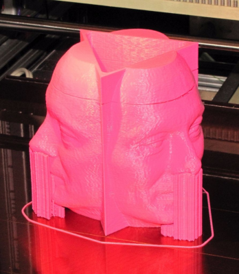
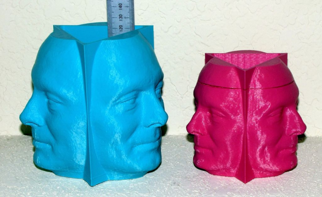
I don't know what sort of "internal" test the German magazine did, but I have a LOT of experience with ABS both in and out of enclosures. You can print small parts with ABS with no enclosure. If you try to print parts that are more than a few cm tall, you will have delamination problems.
This is typical of what happens when you try to print an object more than a few cm tall without an enclosure:
This illustrates the improvement you get when using an enclosure at 45C:
Ultra MegaMax Dominator 3D printer: [drmrehorst.blogspot.com]
This is typical of what happens when you try to print an object more than a few cm tall without an enclosure:
This illustrates the improvement you get when using an enclosure at 45C:
Ultra MegaMax Dominator 3D printer: [drmrehorst.blogspot.com]
|
Re: Connecting extruded aluminium? January 03, 2016 09:01PM |
Registered: 9 years ago Posts: 346 |
Dentist is 100% right. I will just add that it is HEIGHT we are talking about here. As long as the parts are kept close to the heated bed most ABS parts can be made. My corners as previously shown are in ABS.
However - As soon as you try to make anything high like the faces shown by Dentist you will have problems. Not always, but enough so that you cannot leave a print like Dentist show and expect to come back to a finished good print. There are so many people talking about bed adhesion with ABS and in my opinion it is only the tip of the iceberg. I have so good bed adhesion with my ABS that I have literally broken bits off my tempered glass plate from trying to remove a print while it was still hot.
Bed adhesion is not the problem - Cracks like Dentist shows in his photo is.
DO note that there are some confusion between a closed chamber and a heated chamber. Those are not the same. The enclosure that the smartrapcore makes with its wood panels is not what is being referred to. The only thing such an enclosure (even if it is all around) is make sure that small gusts of wind does not interfere. I believe the German magazine if they said that this does not really make any difference.
What matters is to have a heated enclosure where you actively, with heaters, keeps a much higher ambient temperature. Such a setup is much more complicated to make and few printers have this. I am in the progress of making this for one of my printers as I have come to the same realization as Dentist on this subject.
@ Snari - Thank you for the correction. At just 2.7 euro per plate I now see no reason not to buy these and slap them on if sticking to 2020.
|
Re: Connecting extruded aluminium? January 03, 2016 10:16PM |
Registered: 11 years ago Posts: 5,780 |
In my printer, all the heat in the chamber is provided by the bed heater and to a much lesser extent, the extruder, and X and Z axis motors. You may be able to do the same, depending upon your printer's construction and the bed heater power. It isn't difficult or expensive to add additional heat by adding either a large resistor with a small fan or a small room heater with a built in fan. You can put unused temperature input on your printer's controller board to work monitoring the chamber temperature and switch power to the supplemental heater as needed to regulate the temperature.
Ultra MegaMax Dominator 3D printer: [drmrehorst.blogspot.com]
Ultra MegaMax Dominator 3D printer: [drmrehorst.blogspot.com]
|
Re: Connecting extruded aluminium? January 05, 2016 12:59AM |
Registered: 9 years ago Posts: 1,699 |
Normally my controller board only supports one Extruder, but I am lucky to use either an extension board which I have already here (unsure if I will extend my Ormerod 2, too) or to buy the newer version of the board. We will see.
I am not convinced about your closed chamber design. i guess the magazine only looked at the stickiness and warping regarding the heated bed. I have not planned to print such big parts in ABS. ABS printing for me is only for printer parts or other parts where I need special requirements. Otherwise all prints will be done in PLA or PETG.
However last night I make a decision. I should not have said somewhere above that I will not do one of these option in any case. No I will do it. Okay not exactly. To be more precise:
I will get wooden panels either in black or paint them black. Thickness probably 20mm. The color and the thickness makes the difference, but it will not look good. My local Hardware store could cut it to length. it seems to be very cheap (I have no prices yet). You can easy connect them (Just use some screws) and it is very stable. It will offer me a closed chamber including isolation so that the heat will not get lost. And I can put the electronics easily to the outside. All components could be mounted by self-cutting screws, in Germany called "Spax".
As this is my first design and I do not know if this will work, it is the best and only option I have. The only disadvantage is that I cannot implement all my surprises in full details. However I will need some extrusion to make the axes stronger and to stabilize them.
The only thing I do not know that is how I would design the front door, but for the beginning I have no need for a roof or a front, but it can later be easily added to provide a closed chamber.
So that design should be stable enough to provide high print speeds and good accuracy. The isolating factor should be high enough to provide a heated and heatable chamber. If it is painted or ??? (how do you call these parts which will be ironed to the wood) you have a good protection. It is cheap. What do you want more? Look at all the CTC printers and clones it is nothing different
Many thanks for your support.
Slicer: Simplify3D 4.0; sometimes CraftWare 1.14 or Cura 2.7
Delta with Duet-WiFi, FW: 1.20.1RC2; mini-sensor board by dc42 for auto-leveling
Ormerod common modifications: Mini-sensor board by dc42, aluminum X-arm, 0.4 mm nozzle E3D like, 2nd fan, Z stepper nut M5 x 15, Herringbone gears, Z-axis bearing at top, spring loaded extruder with pneumatic fitting, Y belt axis tensioner
Ormerod 2: FW: 1.19-dc42 on Duet-WiFi. own build, modifications: GT2-belts, silicone heat-bed, different motors and so on. Printed parts: bed support, (PSU holder) and Y-feet.
Ormerod 1: FW: 1.15c-dc42 on 1k Duet-Board. Modifications: Aluminium bed-support, (nearly) all parts reprinted in PLA/ ABS, and so on.
I am not convinced about your closed chamber design. i guess the magazine only looked at the stickiness and warping regarding the heated bed. I have not planned to print such big parts in ABS. ABS printing for me is only for printer parts or other parts where I need special requirements. Otherwise all prints will be done in PLA or PETG.
However last night I make a decision. I should not have said somewhere above that I will not do one of these option in any case. No I will do it.
 Okay not exactly. To be more precise:
I will get wooden panels either in black or paint them black. Thickness probably 20mm. The color and the thickness makes the difference, but it will not look good. My local Hardware store could cut it to length. it seems to be very cheap (I have no prices yet). You can easy connect them (Just use some screws) and it is very stable. It will offer me a closed chamber including isolation so that the heat will not get lost. And I can put the electronics easily to the outside. All components could be mounted by self-cutting screws, in Germany called "Spax".
As this is my first design and I do not know if this will work, it is the best and only option I have. The only disadvantage is that I cannot implement all my surprises in full details. However I will need some extrusion to make the axes stronger and to stabilize them.
The only thing I do not know that is how I would design the front door, but for the beginning I have no need for a roof or a front, but it can later be easily added to provide a closed chamber.
So that design should be stable enough to provide high print speeds and good accuracy. The isolating factor should be high enough to provide a heated and heatable chamber. If it is painted or ??? (how do you call these parts which will be ironed to the wood) you have a good protection. It is cheap. What do you want more? Look at all the CTC printers and clones it is nothing different
Many thanks for your support.
Slicer: Simplify3D 4.0; sometimes CraftWare 1.14 or Cura 2.7
Delta with Duet-WiFi, FW: 1.20.1RC2; mini-sensor board by dc42 for auto-leveling
Ormerod common modifications: Mini-sensor board by dc42, aluminum X-arm, 0.4 mm nozzle E3D like, 2nd fan, Z stepper nut M5 x 15, Herringbone gears, Z-axis bearing at top, spring loaded extruder with pneumatic fitting, Y belt axis tensioner
Ormerod 2: FW: 1.19-dc42 on Duet-WiFi. own build, modifications: GT2-belts, silicone heat-bed, different motors and so on. Printed parts: bed support, (PSU holder) and Y-feet.
Ormerod 1: FW: 1.15c-dc42 on 1k Duet-Board. Modifications: Aluminium bed-support, (nearly) all parts reprinted in PLA/ ABS, and so on.
|
Re: Connecting extruded aluminium? January 05, 2016 08:33AM |
Registered: 11 years ago Posts: 5,780 |
If you are using wood panels on the sides of the printer, think about how you're going to access the printer mechanism/wiring/electronics for repairs, upgrades, and maintenance. If the panels are fixed you'll be cursing yourself every time you have to make some sort of change or adjustment.
Ultra MegaMax Dominator 3D printer: [drmrehorst.blogspot.com]
Ultra MegaMax Dominator 3D printer: [drmrehorst.blogspot.com]
|
Re: Connecting extruded aluminium? January 05, 2016 01:18PM |
Registered: 9 years ago Posts: 1,699 |
I really do know about this problem as I often could have cursed other persons if you are laying in the dirt and could not reach a cable properly for example. You are stretching yourself and you cannot see anything only feel your workspace. Luckily I am working now as Engineer and not as a service man anymore.
So I will do it like the following:
I will design the printer without the wooden housing. This will be added at last. For stability reasons I have planned to fix as many wood panels as I could. Only the roof and the front will be left opened.
When mounting (it is a long long way or maybe not?) I will build the housing first completely.
While designing and mounting I will keep an eye of the accessibility of course as I do not want to make my life harder as needed. Maybe I have to plan some access panel or I use at one side wooden extrusion with some sort of door.
For the moment it should be all accessible via the front or the roof. Do not forget the building high is 500mm so the front entry is approximate 400x600mm roughly guessed. The electronics will be mounted at the back panel. Maybe there will be a problem with the weight so I guess I should prefer to mount the CoreXY-motors at the front and the spool holders at the side panels?
The best solution would be to mount the PSU to the bottom panel but then I may get trouble with the cooling, but the design will show. I can only do some speculations at the moment and I guess that during the designing phase starting at the weekend I will get some new ideas.
For me it is mostly important to get a stable frame so the use of my stepper motors with 400 steps does make sense and I can profit from their higher resolution.
Today I was lucky to purchase three spools ABS in different colors for the price of only one by a private seller. The only problem is that they had been opened but not used.
One Off-Topic question: I often read that you should add a fan if you heat the chamber. But what about the air flow? Isn't this a problem for the printed parts?
Slicer: Simplify3D 4.0; sometimes CraftWare 1.14 or Cura 2.7
Delta with Duet-WiFi, FW: 1.20.1RC2; mini-sensor board by dc42 for auto-leveling
Ormerod common modifications: Mini-sensor board by dc42, aluminum X-arm, 0.4 mm nozzle E3D like, 2nd fan, Z stepper nut M5 x 15, Herringbone gears, Z-axis bearing at top, spring loaded extruder with pneumatic fitting, Y belt axis tensioner
Ormerod 2: FW: 1.19-dc42 on Duet-WiFi. own build, modifications: GT2-belts, silicone heat-bed, different motors and so on. Printed parts: bed support, (PSU holder) and Y-feet.
Ormerod 1: FW: 1.15c-dc42 on 1k Duet-Board. Modifications: Aluminium bed-support, (nearly) all parts reprinted in PLA/ ABS, and so on.
|
Re: Connecting extruded aluminium? March 02, 2016 03:41AM |
Registered: 9 years ago Posts: 1,035 |
I see no reason why not to use the first suggestion of the @the_digital_dentist. You can buy a tap for a few plates worth of moneys and you can use that many times.
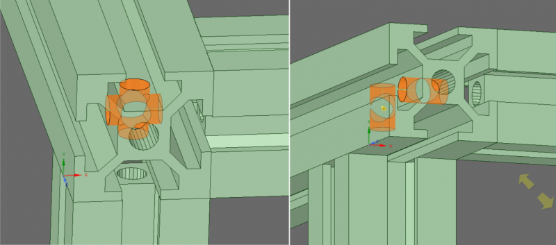
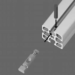
I don't see though, and that's why I seem to be reviving a stalled thread, how to connect a vertical extrusion to the already formed corner?. Drilling another cross-hole to the already existing one for the allen key would weaken too much the extrusion, unless it was a very tiny one. Please correct me if I am wrong.
I can easily imagine how a plane could be constructed in this manner. Then make two planes and connect the third extrusion (the vertical) with plates or brackets. Or use a corner cube block (expensive).
The only way to still use the tap-screw method for all the frame is to offset the vertical columns and have a second hole close to the first one on two of the plane's sides.
The comparison example in the image below:
Also about the wooden panels bolted to the frame: won't the wood (low coefficient of thermal expansion) and ALU (not low, not near wood's) just twist the frame trying to accommodate their specific expansion coefs? Moreover, due to humidity, won't wood pull on the aluminum in an unpredictable manner thus twisting the frame even more? I believe bracing with steel or aluminum is better for a metal frame.
Edit: Of course one could use T-Slot End Connectors like this one below, which would use the already existing hole:
But I have no idea where to get those, how much they cost and they also require a ball headed hex key to pre-tighten and then use the L-key to fasten.
Edited 3 time(s). Last edit at 03/02/2016 04:26AM by realthor.
RepRap Lander concept on Concept Forge
RepRap Lander concept on RepRap Forums
My Things, mostly experimental stuff
|
Re: Connecting extruded aluminium? March 05, 2016 10:13AM |
Registered: 11 years ago Posts: 5,780 |
You don't want to create a hurricane, but running a small fan to keep the warm air circulating and blowing across the heater won't hurt. I added such a system to a solidoodle printer at the makerspace recently. I used a 208V fan but operate it at 117VAC so it turns relatively slowly and very quietly. You could do the same with a DC fan- most 24V fans will start reliably and run a little slow and very quietly on 12V.
I don't think drilling a second tool access hole weakens the extrusion enough to make any difference in its performance. A lot of the stiffness comes from the outer parts of the extrusion. The center tube isn't a very large part of the extrusion's cross sectional area.
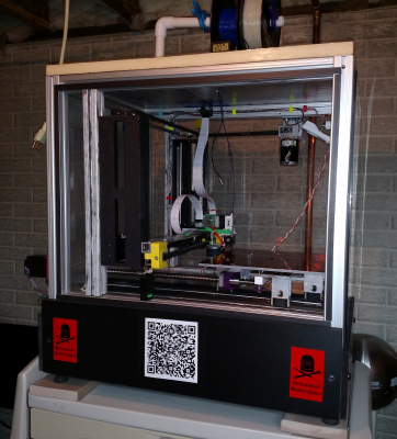
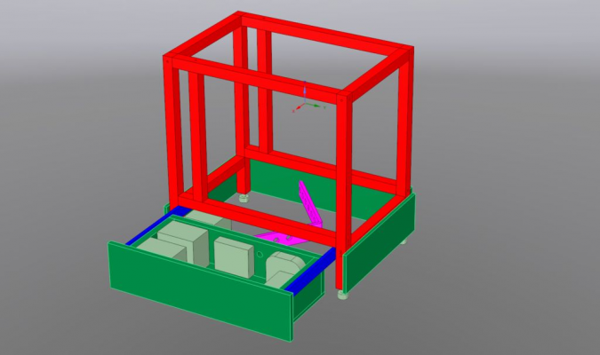
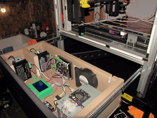
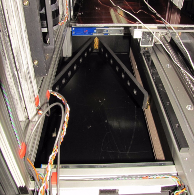
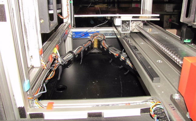
I enclosed my printer but kept everything accessible at the same time using two methods- the electronics are housed in a drawer at the bottom of the printer, and the side panels are attached using magnetic tape that seals almost air tight but allows easy removal just by pulling on them. I even put the controls inside the drawer so if the machine is displayed publicly they are out of sight which keeps curious fingers away from them. It is not obvious that the drawer is a drawer when it is closed.
In the photo you can see black strips of magnetic tape that hold the polycarbonate front panel on the machine. There are similar strips on the other sides and matching strips on the panels. The top, left side and bottom panels are 1" thick PIR foam insulation board. The top panel is screwed down and the left side and bottom panels are cut so they jam-fit in the frame without any other attachment. It has been pretty cold in my basement workroom so, I replaced the back panel with an insulation panel that has magnetic tape to help contain the heat. I'm finding that that still isn't quite keeping the build chamber temperature as high as I would like so I'm getting ready to add a heater. The black base with the QR code and the red stickers is the drawer panel.
This is how the drawer works:
Edited 2 time(s). Last edit at 03/05/2016 10:30AM by the_digital_dentist.
Ultra MegaMax Dominator 3D printer: [drmrehorst.blogspot.com]
|
Re: Connecting extruded aluminium? March 05, 2016 11:06AM |
Registered: 9 years ago Posts: 1,035 |
You have something worth of displaying publicly allright 
Why do you need the sarrus linkage at the back of the drawer...is there where the cables are routed along to the inside of the printer/power outlet?
I find the magnetic strip a neat idea.
RepRap Lander concept on Concept Forge
RepRap Lander concept on RepRap Forums
My Things, mostly experimental stuff
|
Re: Connecting extruded aluminium? March 05, 2016 12:03PM |
Registered: 11 years ago Posts: 5,780 |
Thanks! It has been a lot of work...
The folded strip at the back of the drawer keeps the cables from dragging on the table under the printer when the drawer is closed. It has lots of holes so I can lash the cables to it using velcro tape strips that make it easy to make changes should the need arise.
Here it is before wiring:
And here's what it looks like with cables in place:
The magnetic strip tape is sold as "matched pole" tape. I found that its adhesive didn't bond well to the aluminum frame of the printer so I used contact cement to attach it and have had no further problems. IRIC, I applied contact cement to the tape strips on the polycarbonate panels, too, just in case. The tape is a little expensive, but is sure does simplify things. The more you buy the cheaper it gets on a per meter basis.
Edited 2 time(s). Last edit at 03/05/2016 12:13PM by the_digital_dentist.
Ultra MegaMax Dominator 3D printer: [drmrehorst.blogspot.com]
|
Re: Connecting extruded aluminium? March 05, 2016 12:31PM |
Registered: 9 years ago Posts: 1,035 |
Lol it reminds me of the DCs I've been cabling (as an IT engineer one does a lot of work outside of the console but it has been most rewarding nevertheless). Cable management is crucial down the road when one has to chase issues. You wouldn't imagine what I could see over the years (hint) (not my own picture, we were not allowed to go with phones in there).
Anyway I hope you make enough money off that printer to be worth it the high quality components and the amount of work you've put in it.
RepRap Lander concept on Concept Forge
RepRap Lander concept on RepRap Forums
My Things, mostly experimental stuff
Anyway I hope you make enough money off that printer to be worth it the high quality components and the amount of work you've put in it.
RepRap Lander concept on Concept Forge
RepRap Lander concept on RepRap Forums
My Things, mostly experimental stuff
|
Re: Connecting extruded aluminium? March 05, 2016 03:44PM |
Registered: 11 years ago Posts: 5,780 |
I don't make money off of it. I print stuff I need with it.
Ultra MegaMax Dominator 3D printer: [drmrehorst.blogspot.com]
Ultra MegaMax Dominator 3D printer: [drmrehorst.blogspot.com]
|
Re: Connecting extruded aluminium? March 05, 2016 04:43PM |
Registered: 9 years ago Posts: 1,035 |
Quote
the_digital_dentist
I don't make money off of it. I print stuff I need with it.
Well it's kind of the same, you save on what you would have paid for somebody else to make for you. And you have control over the process.
RepRap Lander concept on Concept Forge
RepRap Lander concept on RepRap Forums
My Things, mostly experimental stuff
|
Re: Connecting extruded aluminium? March 06, 2016 02:07AM |
Registered: 9 years ago Posts: 1,699 |
So some words again from me.
The drawer is indeed a really nice idea.
I decided to keep at the Extrusion and I also decided not to safe too much money, but it will take some time. Last month I had a small car accident. Luckily no humans were hurt, but the car was old and therefore not repairable. Even though I did not caused the accident I had to spent some money for a new car so therefore the printer has to wait. By the way it is not fully designed.
I will not use the connection with only one screw as this would be too much holes I would have to drill (I have some little problems with my hands). Maybe I will use the fast connectors, but I guess not. Somebody at the German Facebook group got Extrusions which weren't cut angled. I think I will use some brackets.
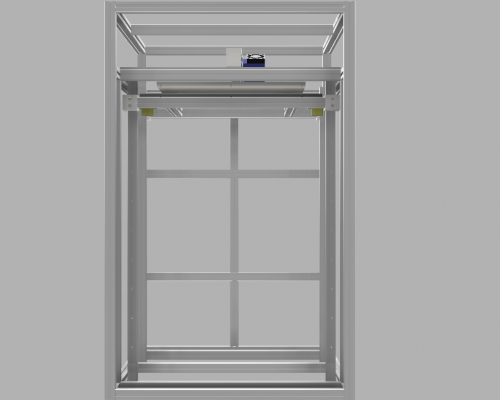
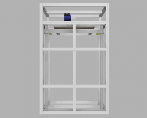
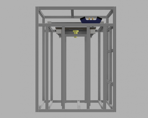
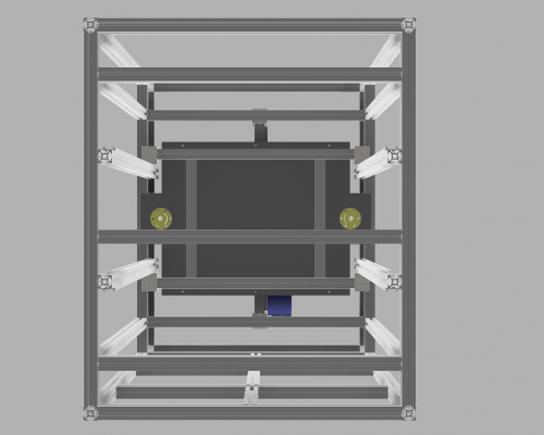
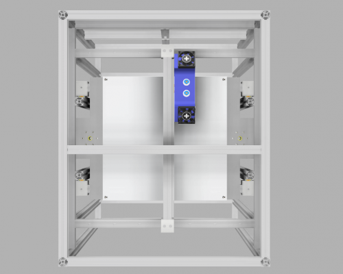
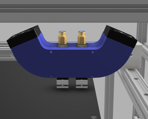
I decided to use 20x20mm Extrusion. Before you say that is too weak please have a look at the current design. The hot-end will be changed. One fan will be flipped to allow a constant airflow and a third fan will be added.
Unfortunately I did not find a suitable push fit as step-file therefore the coloring is wrong.
Slicer: Simplify3D 4.0; sometimes CraftWare 1.14 or Cura 2.7
Delta with Duet-WiFi, FW: 1.20.1RC2; mini-sensor board by dc42 for auto-leveling
Ormerod common modifications: Mini-sensor board by dc42, aluminum X-arm, 0.4 mm nozzle E3D like, 2nd fan, Z stepper nut M5 x 15, Herringbone gears, Z-axis bearing at top, spring loaded extruder with pneumatic fitting, Y belt axis tensioner
Ormerod 2: FW: 1.19-dc42 on Duet-WiFi. own build, modifications: GT2-belts, silicone heat-bed, different motors and so on. Printed parts: bed support, (PSU holder) and Y-feet.
Ormerod 1: FW: 1.15c-dc42 on 1k Duet-Board. Modifications: Aluminium bed-support, (nearly) all parts reprinted in PLA/ ABS, and so on.
|
Re: Connecting extruded aluminium? March 06, 2016 10:27AM |
Registered: 11 years ago Posts: 5,780 |
Wow! It looks like a lot of aluminum parts to cut and screw together! I guess easy and cheap duplication is no longer a high priority.
To me it looks like using two fans to cool the extruders is a bit of overkill and unnecessarily increases the size and mass of the extruder assembly. I suppose you can test it with one fan and if it works OK just reprint the fan mount. It looks like one fan, mounted on the surface facing the viewer in the last image, could easily blow air across both hot-ends.
It's too bad about the car and good that no one got hurt.
Edited 1 time(s). Last edit at 03/06/2016 10:48AM by the_digital_dentist.
Ultra MegaMax Dominator 3D printer: [drmrehorst.blogspot.com]
|
Re: Connecting extruded aluminium? March 06, 2016 10:49AM |
Registered: 9 years ago Posts: 1,699 |
There are indeed a lot of aluminium parts. To be honest I would like to achieve a stable frame with only one sort 20x20mm to get the extrusions cheaper.
Maybe I will get rid of one fan, but I am not sure if I achieve a suitable cooling. I think I will keep the design and replace one fan by a protection guard only so I can easily add a second fan if needed.
The good side looking at the car accident: I like my newer car, but it was not easy to let the old car go as it was nearly 11 years part of my life. Luckily I found someone who thinks who can fix it.
Slicer: Simplify3D 4.0; sometimes CraftWare 1.14 or Cura 2.7
Delta with Duet-WiFi, FW: 1.20.1RC2; mini-sensor board by dc42 for auto-leveling
Ormerod common modifications: Mini-sensor board by dc42, aluminum X-arm, 0.4 mm nozzle E3D like, 2nd fan, Z stepper nut M5 x 15, Herringbone gears, Z-axis bearing at top, spring loaded extruder with pneumatic fitting, Y belt axis tensioner
Ormerod 2: FW: 1.19-dc42 on Duet-WiFi. own build, modifications: GT2-belts, silicone heat-bed, different motors and so on. Printed parts: bed support, (PSU holder) and Y-feet.
Ormerod 1: FW: 1.15c-dc42 on 1k Duet-Board. Modifications: Aluminium bed-support, (nearly) all parts reprinted in PLA/ ABS, and so on.
Sorry, only registered users may post in this forum.
