|
FLSUN I3 kit review August 07, 2016 01:15PM |
Registered: 7 years ago Posts: 34 |
Hi. Longtime lurker, first time poster.
I have a couple of friends with acrylic kits (they got me hooked ) and eventually went looking for a kit. I'm an engineer by training, and have been aware of the strengths and weaknesses (literally and metaphorically) of the various styles of machine frames. I had actually 3-D'd a design with 1"x1" extrusion because I wanted the rigidity of a metal frame.
Then I saw the FLSUN kit. 20mm x 20mm frame, all parts included, for $219, free shipping. Busted. Sent in the order and in 5 days the kit showed up at my door.
I've dealt with electronic prototyping of all kinds, up to refrigerator-size and bigger things that became entire computer systems, since the early 70s, so I think I'm qualified to critique a kit.
This one is good. It's 20mm x 20mm T-slot extrusion, glossy black paint, with fittings and hardware where appropriate.All parts and pieces were included. Moreover, they **fit** together, which has not always been true for kits I've seen in the past. The parts other than the frame were either 3D printed fittings or laser-cut ~8mm acrylic pieces. The instruction manual, along with STL files for the printed pieces and parts lists came on an SD card in the box. The instruction/assembly manual was 148 pages of pictures with arrows and text for what to use and how to fit it. Total assembly time was maybe three hours, and I stretched it out because I actually savor that kind of thing. I'm taking my time getting wire routing down to how I like it and making sure that things don't get pinched in the motion, etc.
There were only the most trivial of errors in the manual. The big one was where a 350mm length was specified as "350cm". Not hard to figure that one out! The hardware screws and such were carefully put into small ziploc bags with the size of the screw (M2.5, M3, M4, etc.) marked on the bag. This is GOOD practice for a kit.
The kit came with a 12V/16A power supply included, and 1kg of PLA filament in a (still...) vacuum sealed bag. And that's where the few problems that exist begin. The packaging was very nice indeed. The outer box was sturdy, and inside was the film-wrapped extrusion on bottom, metal rods, and a group of secondary boxes. The secondary boxes contained parts sorted by type and stage of assembly. These boxes fit neatly into groups around the outside, leaving a central cavity that neatly contained the 1kg spool of filament and the power supply in its own cardboard box. In the bard's words, aye, there's the rub.
In shipping, nothing at all was damaged - except the power supply. It had been bashed on by the filament spool banging back and forth inside the central opening. It's thin metal cover had been squashed and bashed down, and one corner of the PCB at the screw-connectors end was cracked. I send an email to the online store that sells this kit, and within minutes received an automated reply that the problem had been forwarded to the appropriate people.
After that automated reply, I got ...nothing at all. It's going on two weeks now, and even after a second email to them, containing pictures of the power supply damage, I have received nothing. Zero. Zilch. Nada. Well, OK, a second automated reply, but no matter how polite their machine is, it's not as good as getting some attention to the damaged power supply.
This has kept me from actually firing the thing up. It reminds me of a joke about a cheap car, long ago: "The dials and gauges were clearly marked, well lit, and easy to read. However their utility was reduced by the fact that they were merely printed on cardboard, not actually connected up to anything."
I'm a big boy. I got a good kit of parts that went together well. I can find and hook up another power supply, but that will add another $20 - $30 to the cost of the kit. But I find it baffling to have such a very, very well executed kit of parts and instruction manual completely invalidated by the failure to stick some crumpled paper into the space between a rollaround filament spool and a power supply box.
Net evaluation:
Parts Quality: very good indeed
Kit Completeness: very good indeed
Instructions Quality: very good indeed
Customer Support: The very worst possible or imaginable.
Overall: Only buy this kit if you can cope with repairing or replacing anything that might be broken or missing. There is no customer support at all.
It's a pity. They came so close.
I have a couple of friends with acrylic kits (they got me hooked
) and eventually went looking for a kit. I'm an engineer by training, and have been aware of the strengths and weaknesses (literally and metaphorically) of the various styles of machine frames. I had actually 3-D'd a design with 1"x1" extrusion because I wanted the rigidity of a metal frame. Then I saw the FLSUN kit. 20mm x 20mm frame, all parts included, for $219, free shipping. Busted. Sent in the order and in 5 days the kit showed up at my door.
I've dealt with electronic prototyping of all kinds, up to refrigerator-size and bigger things that became entire computer systems, since the early 70s, so I think I'm qualified to critique a kit.
This one is good. It's 20mm x 20mm T-slot extrusion, glossy black paint, with fittings and hardware where appropriate.All parts and pieces were included. Moreover, they **fit** together, which has not always been true for kits I've seen in the past. The parts other than the frame were either 3D printed fittings or laser-cut ~8mm acrylic pieces. The instruction manual, along with STL files for the printed pieces and parts lists came on an SD card in the box. The instruction/assembly manual was 148 pages of pictures with arrows and text for what to use and how to fit it. Total assembly time was maybe three hours, and I stretched it out because I actually savor that kind of thing. I'm taking my time getting wire routing down to how I like it and making sure that things don't get pinched in the motion, etc.
There were only the most trivial of errors in the manual. The big one was where a 350mm length was specified as "350cm". Not hard to figure that one out!
The hardware screws and such were carefully put into small ziploc bags with the size of the screw (M2.5, M3, M4, etc.) marked on the bag. This is GOOD practice for a kit.The kit came with a 12V/16A power supply included, and 1kg of PLA filament in a (still...) vacuum sealed bag. And that's where the few problems that exist begin. The packaging was very nice indeed. The outer box was sturdy, and inside was the film-wrapped extrusion on bottom, metal rods, and a group of secondary boxes. The secondary boxes contained parts sorted by type and stage of assembly. These boxes fit neatly into groups around the outside, leaving a central cavity that neatly contained the 1kg spool of filament and the power supply in its own cardboard box. In the bard's words, aye, there's the rub.
In shipping, nothing at all was damaged - except the power supply. It had been bashed on by the filament spool banging back and forth inside the central opening. It's thin metal cover had been squashed and bashed down, and one corner of the PCB at the screw-connectors end was cracked. I send an email to the online store that sells this kit, and within minutes received an automated reply that the problem had been forwarded to the appropriate people.
After that automated reply, I got ...nothing at all. It's going on two weeks now, and even after a second email to them, containing pictures of the power supply damage, I have received nothing. Zero. Zilch. Nada. Well, OK, a second automated reply, but no matter how polite their machine is, it's not as good as getting some attention to the damaged power supply.
This has kept me from actually firing the thing up. It reminds me of a joke about a cheap car, long ago: "The dials and gauges were clearly marked, well lit, and easy to read. However their utility was reduced by the fact that they were merely printed on cardboard, not actually connected up to anything."
I'm a big boy. I got a good kit of parts that went together well. I can find and hook up another power supply, but that will add another $20 - $30 to the cost of the kit. But I find it baffling to have such a very, very well executed kit of parts and instruction manual completely invalidated by the failure to stick some crumpled paper into the space between a rollaround filament spool and a power supply box.
Net evaluation:
Parts Quality: very good indeed
Kit Completeness: very good indeed
Instructions Quality: very good indeed
Customer Support: The very worst possible or imaginable.
Overall: Only buy this kit if you can cope with repairing or replacing anything that might be broken or missing. There is no customer support at all.
It's a pity. They came so close.
|
Re: FLSUN I3 kit review October 24, 2016 04:32AM |
Registered: 7 years ago Posts: 16 |
I just finished building this kit. Also have a engineering background and just couldn't go for an acrylic frame. This does have a few easily replaceable acrylic parts used for mounts and bracing the gantry tower pieces.
The kit provides extra hardware which is handy. When finished it is a solid tank! Everything fits perfectly. My kit arrived with a bit of bruising but inside everything was tightly packed and in good shape so I didn't have to try and get the court our to pay for shipping damages unlike the OP. My main complaints about the kit revolve around the build and user manuals. They were unclear in a few places but I was able to figure things out with information from these forums. And the forum and other sources of info were listed in the manual. Minor complaints would be that the manual and any pictures don't actually show the wiring layout. This is how to place the various boards and then run all the wires from steppers and so on to the boards. If you try to run them as they show in the few pictures you find the wires are nowhere near long enough. And if you look at the rest of the pictures hoping for hints you find that nothing is actually connected lol. They must have given a kit to a photographer who made it look pretty not realistic. Oh and I had to get extra zip ties and spiral wrap to make mine all pretty lol.
After all the issues big small and imagined I would still highly reccomend this kit. It is solid, quiet, very complete and prints a wide variety of materials. I also experienced slow or no response from the manufacturer. The dealer however was very prompt and tried to help. 3dprintersonlinestore.com
|
Re: FLSUN I3 kit review October 24, 2016 04:32AM |
Registered: 7 years ago Posts: 16 |
|
Re: FLSUN I3 kit review October 24, 2016 07:09PM |
Registered: 7 years ago Posts: 10 |
... and here's a contrary opinion.
I bought this kit based on the above review. My risk was small, since I already have a good working printer (Original Prusa i3 MK2) and I also have a hardware design background. I expected to have to do a few minor tweaks to get this working. Wrong!
1) The Z axis rods are listed as 10mm in both assembly and BOM, but the kit supplied 8mm rods. This is evidently the 'new' standard according to 3DPrintersOnline.
2) The X axis L&R ends REQUIRE that both the Z axis rods AND the acme screws are fixed at both ends, but the acme rods have no top supports. This results in the ends twisting when the X-axis belt is tightened, causing the bottom X-axis carriage rod to FALL OUT of the left-side end. There is an extended top support supplied as an STL file on the SD card, but! it is designed for 10mm rods and 10mm acme screws.
3) The bottom X-axis rod is evidently too short for the ends supplied (see #2).
4) The quality of the printed parts is horrible, especially where any of the smooth linear rods is concerned. None of the rod supports actually fit properly - they're all too loose.
5) The MK5 clone hot end is a fire just waiting to occur. The instructions supplied manage to skip over the hot end assembly entirely, and the online copy shows the thermistor simply placed in the hot end without anything holding it in. This heating element is held in place with a single grub screw that applies absolutely NO clamping force around the element at all.
6) The heatbed - a MK3 (nice!) - only has 180mm of usable travel in the Y direction due to the design of the belt routing off the Y-axis stepper. Also, the heatbed support frame is acrylic, which WILL sag after a bit of use due to the MK3 heatbed being all aluminum. The wiring is insufficient gauge and yet another fire waiting to happen.
7) The frame is nice. The steppers are adequate. The RAMPS board is of questionable quality. The heatbed is a MK3.
All in all, I'm able to salvage the frame, the steppers, the heatbed (after replacing the hot leads), and the endstops. I've had to redesign all three axes, source a support frame for the heatbed, replace the hotend entirely, and buy another controller board. Now, I admit that I could probably get by with the RAMPS board supplied, but my confidence in the overall quality of the kit is so low that I'm not willing to trust it.
Edited 1 time(s). Last edit at 10/24/2016 07:11PM by markshur.
|
Re: FLSUN I3 kit review October 29, 2016 06:31PM |
Registered: 7 years ago Posts: 34 |
I expected even some moderate changes to get it into a workmanlike state. I judge that it made that standard. Different expectations.Quote
markshur
I bought this kit based on the above review. My risk was small, since I already have a good working printer (Original Prusa i3 MK2) and I also have a hardware design background. I expected to have to do a few minor tweaks to get this working. Wrong!
Didn't notice. Put in the supplied rods and bearings. They fit, and worked. It's a low end machine. If I wanted super-solid and super rigid, I'd probably design my own (which is actually in progress, and I have received the 12mm X-axis rods and bearings as well as the aluminum stock for implementing the axis). What I got works OK.Quote
1) The Z axis rods are listed as 10mm in both assembly and BOM, but the kit supplied 8mm rods. This is evidently the 'new' standard according to 3DPrintersOnline.
That would be annoying, OK. Mine don't fall out. I expect to take off the X-axis and drill/tap setscrews for the linear guide rods to fix this. This will also fix the issue with flexing inwards of the Z-guides and leadscrews when tightening the belt. I may not have hit this yet, because I have yet to print anything more than about 1/3 of Z-height capability.Quote
2) The X axis L&R ends REQUIRE that both the Z axis rods AND the acme screws are fixed at both ends, but the acme rods have no top supports. This results in the ends twisting when the X-axis belt is tightened, causing the bottom X-axis carriage rod to FALL OUT of the left-side end. There is an extended top support supplied as an STL file on the SD card, but! it is designed for 10mm rods and 10mm acme screws.
But issues like this did lead me to dump the supplied STLs into FreeCAD and 3d-trace them into FreeCAD objects so they can be reprinted with modifications.
As I said, this hasn't happened to me.Quote
3) The bottom X-axis rod is evidently too short for the ends supplied (see #2).
I did go look, and none of my rod supports are off by 2mm diameter. I suspect that you may have received a machine that had the 10mm-printed parts with the "new standard" 8mm rods. One option for a quick fix would be to Loctite some 10mm bushings on the 8mm rod ends where they go into the printed parts, or to re-print the holders after magic-CADing them. I'd be happy to help with that If I can.Quote
4) The quality of the printed parts is horrible, especially where any of the smooth linear rods is concerned. None of the rod supports actually fit properly - they're all too loose.
Yeah, I wasn't all that happy with that, either. My solution after initial proving trials is probably going to be to use some high-temp and thermally conductive epoxy to fit them in. The aluminum block could be drilled and tapped for another holder, etc. There are a number of solutions.Quote
5) The MK5 clone hot end is a fire just waiting to occur. The instructions supplied manage to skip over the hot end assembly entirely, and the online copy shows the thermistor simply placed in the hot end without anything holding it in. This heating element is held in place with a single grub screw that applies absolutely NO clamping force around the element at all.
And as, my friend with the all acrylic Prusas says, that's what that battery-powered smoke detector attached to the top of his machines is for. They're all potential fire hazards, some more than others.
Hasn't hurt me yet, but then I never intended to stretch it to the last millimeter. I was very happy and my Prusa-friend was envious of the ease of setting up the belts and tensioning, though. One man's fish is another man's poisson.Quote
6) The heatbed - a MK3 (nice!) - only has 180mm of usable travel in the Y direction due to the design of the belt routing off the Y-axis stepper.
Yeah, I didn't partlcularly like that, either. However, it does work. And the heat bed and support frame are getting some design attention, about which, see below.Quote
Also, the heatbed support frame is acrylic, which WILL sag after a bit of use due to the MK3 heatbed being all aluminum.
Maybe. This chart wire sizes and ampacities shows the ampacity of 16ga (mine is; I was worried and measured) as 22 when used as "chassis wiring", which is what this is. I've worked in power supply design for a number of years, and I'd say that 16 is OK, but nothing smaller would be. If the power was changed to 24V, the current would drop by 4, and the wires would be overkill. So for 12V, it's marginal or OK, depending on the heatbed resistance. It just has to stay under 22A, and that means the heat bed resistance has to be more than 0.545 ohms. Most of them are. Mine measures 1.2 ohms, and the wires do not get noticeably warm with the bed at max continuous heating; about which, see below.Quote
The wiring is insufficient gauge and yet another fire waiting to happen.
Frame, stepper, heatbed, yes. The RAMPS board is of mysterious quality as opposed to questionable, using the normal USA English connotations of those words. Both of mine worked without a hitch when I got them plugged up correctly.Quote
7) The frame is nice. The steppers are adequate. The RAMPS board is of questionable quality. The heatbed is a MK3.
On the control board. The board is a "BT7272A RAMPS 1.4 Plus". It's made by a Chinese company and solder under the "3DYMY" brand. They make and provide this to other makers of 3d Printer kits. I did my power supply design work, and many other things for A Major Computer Manufacturer over the course of a few decades. The board is, again, OK-ish. I have found no real quality issues from the outside, and both of mine do work as advertised. It's very tightly integrated. On the other hand, both of mine have survived mis-wiring and mis-plugging, and that made me happy.
My Prusa-friend is envious of the wide range of connections available. This puppy has dedicated headers for a bluetooth adapter, an ethernet/wifi adapter, spare SPI port, a couple of auxillary headers, second extruder, software controlled fan, spare always-on fan and probably other things I haven't found yet.
It uses plug-in motor drivers, which is good as you can replace a killed (did **I** do that???
) motor driver. The A4988 postage stamps are being replaced with the pin-compatible but bigger-current, bigger-voltage, more microsteps DRV8825 boards as soon as the new boards get here. The DRV boards are about $2.10, the A4988 are about $1.70. It uses the "2004LCD" display + SD card assembly, which is available on ebay for under $9. I like having spares available. So much that I found a supplier of the 3DYMY controller board and bought a spare. $35 - once you find them. My Prusa friend is envious that his printers had an SD on the controller, not remoted off to the front panel.
The board uses a 7805 that is capable of working from 24V, and once I found English versions of the 3DYMY specs, they say "can use 24V", which is very nice. Lower current, faster steps, more torque.
My axes work, but admittedly they are not military grade. Of course, I didn't pay for mil-spec, either. Let's talk about a couple of issues I did have and worked around. That will hit a couple of these points.Quote
All in all, I'm able to salvage the frame, the steppers, the heatbed (after replacing the hot leads), and the endstops. I've had to redesign all three axes, source a support frame for the heatbed, replace the hotend entirely, and buy another controller board. Now, I admit that I could probably get by with the RAMPS board supplied, but my confidence in the overall quality of the kit is so low that I'm not willing to trust it.
I don't consider the RAMPS board getting by. It's handy, and no defects noted yet, with two operating. It offers me some things I like, like the second extruder plug, both min and max endstop plugs, the communications headers, auxillary signal headers, and the remote display/SD cable plugs.It works well enough that I was trying to find the firmware to tinker it a bit, not least to activate that beeper on the front panel that doesn't seem to be configurable. I looked for the ICSP programming port and .. uh-oh, there isn't one.
However, all the ICSP signals are on the SD card ribbon cable header with the exception of "reset", which does not seem to be brought off-board. Oh, well. I soldered a single square pin to one side of the "reset" tactile switch, and was able to read and write the binaries of the ATMEGA2560. So I can archive the binaries, as well as update firmware. The firmware is MARLIN as it was supplied to me. Took some sleuthing to find that. But I can now implement the Arduino IDE and make tinkering with the config.
I had other issues bother me enough to want to correct them. I do not like the Z-axis endstop/min switch implementation at all. I was working on a micrometer-adjust setup for the Z-switch on the frame when I found the Crocker differential IR Z-probe. That thing's GREAT. I modified some PCB stock to let me hang the IR probe from the fan on the front of the hot end. Major, major improvement in Z-axis leveling and accuracy.
One reason to buy this one instead of acrylic frame units was the aluminum frame. I was disappointed in finding an acrylic bed support. That will sag, as you note. However, there are some other things happening that will put that off for a while.
First, my heaters will not get above 97C in free air, with bed heat current on 100% of the time. This thing really needs an insulator under the heat bed. It needs an aluminum heat spreader, which the second of mine has, but the first does not. I found a guy here in town that sells ceramic-fiber felt insulation in square feet. I now have two one-square-foot slabs. The are being changed to (from the top surface):
- glass
- aluminum spreader
- heat bed
- ceramic blanket
- blanket support
Four-point leveling is a misery. I designed some three-point enhancements. The third point hole in the heat bed is marginal, especially being between +12 and ground. I drew up some rails made from 1/6" aluminum angle, nominally 1"x1" size, a Home Depot/Lowes stock item. One leg is cut down from 1" to 6mm/1/4" to make it a very un-equal angle.The wide side has 4.1mm holes drilled at 104.5mm from the center of the angle's length (that is at each end) and 6mm in from both the corner side and the non-corner side. There is a fifth 4.1mm hole 6mm in from the middle on the corner side of the angle. Make four identical.
The bed stack is assembled onto two of the rails. The rails run down the sides of the bed, not front and back, and attached with bed mounting screws to the non-corner edge of the rail. This makes the rail about 16mm wider on each side, which I think will clear everything. (I'm about to find that out soon as I get some workshop time.) The other pair of rails are assembled to the acrylic bed frame, along the sides, with the corner-side of the rail out and pointed down. This leaves three holes on each rail that can be aligned vertically on either side of the heat bed/frame. An M4-50 comes up through the bottom/frame rails, has a spring put over it, and has the top bed/rails settled on top and is held in place on top of the heatbed rail with an M4 knurled thumb-nut and lock thumbnut. Two go on the ends on one side of the heatbed, one in the center of the other side. This gives three point leveling, but with the adjusters on top, not under, the bed, and all three adjusters lock-able.
Like I say, we'll see as soon as I get some workshop time.
I also mounted the power supply, a front panel illuminated power switch, and an IEC power inlet on 2"x2" aluminum angle at the left front and back corners to alleviate some of the issues with AC wiring. The display is mounted on the front right corner on some nylon spacers to get it far enough forward to clear the bed at max-forward position. The controller card is on a laser-cut acrylic panel on the back of the right side, where I could get at plugging and unplugging wires.
|
Re: FLSUN I3 kit review November 01, 2016 04:16PM |
Registered: 7 years ago Posts: 10 |
A couple of clarifications.
Re the 8mm/10mm issue, the printed parts supplied are for 8mm rods, but the print quality is so poor they might as well be designed for 9mm. Yes, there is that much excessive clearance - my comment about the bottom X rod falling out is not exaggerated. The STL files are all for 10mm rods, so you cannot simply reprint the parts with the files supplied, and if I'm going to have to CAD up new files I might as well fix the design so it actually works.
Re the RAMPs, I've already admitted that it is probably okay. However, clone RAMPs boards vary widely in quality, and one of the known failure symptoms on poor quality boards is a catastrophic failure of the flammable variety. I already have a spare 4x Smoothie and GLCD I can use for this build, so this RAMPS goes into the spare parts bin until I can give it a proper QC check and BVT. I may not have as much hardware experience as you do, but I do have 10 years previous experience as a product design engineer in embedded processing for industrial and machine controls to draw from.
Counting the clone V5 that came with the kit as a total loss is not a big deal since I have a spare E3D V6-Lite (original, not clone) from my Prusa MK1 to MK2 upgrade. However, even if I didn't have a ready replacement I wouldn't trust the one from the kit under any circumstances - the design deficiencies are *that* bad.
One additional thing I failed to mention is that the PSU is inadequate for the parts supplied. The kit comes with a 200W PSU (12 @ 16.6A). The MK3 heat bed draws anywhere from 8A to 12A, the hot end 2.5A, each stepper is rated for 1.5A, so you have a potential peak draw of 18A to 22A even before you add in any of the controller and display electronics. A 300W PSU is the minimum for this build and this may account for your heatbed's inability to reach a usable ABS temp. 4mm cork tile is a good alternative for insulation if you don't want to replace the acrylic carrier. I'm tempted to cover the MK3 with a sheet of adhesive PEI since the MK2 has shown that it works well for my prints. Adding a BLTouch to the hot end mount allows for grid compensation and helps minimize the leveling requirements.
As soon as I get some free time I'll post some pics of the mods that I've done to this build. I'm still working on redoing the Z axis and X carriage assemblies and this is not a high priority project, so it may take me a few weeks to complete the conversion.
|
Re: FLSUN I3 kit review November 01, 2016 07:39PM |
Registered: 7 years ago Posts: 34 |
Makes sense. I can stuff the STLs into Freecad and "trace" them if that would help you. It might be worth looking for some suitable bushings for a temp fix til you could print new fittings. I did correspond with an FLSun buyer whose nozzle carriage had drooped so that the nozzle would not fit in. A friend printed her a new one from the supplied STLs and it worked for her. The quality of the printing is likely to be ... variable...Quote
markshur
Re the 8mm/10mm issue, the printed parts supplied are for 8mm rods, but the print quality is so poor they might as well be designed for 9mm. Yes, there is that much excessive clearance - my comment about the bottom X rod falling out is not exaggerated. The STL files are all for 10mm rods, so you cannot simply reprint the parts with the files supplied, and if I'm going to have to CAD up new files I might as well fix the design so it actually works.
Again, reasonable. If you have spares, it makes sense to use them. I just haven't run into issues with these boards yet.Quote
Re the RAMPs, I've already admitted that it is probably okay. However, clone RAMPs boards vary widely in quality, and one of the known failure symptoms on poor quality boards is a catastrophic failure of the flammable variety. I already have a spare 4x Smoothie and GLCD I can use for this build, so this RAMPS goes into the spare parts bin until I can give it a proper QC check and BVT.
It's a pleasure to deal with someone who's experienced.Quote
I may not have as much hardware experience as you do, but I do have 10 years previous experience as a product design engineer in embedded processing for industrial and machine controls to draw from.
We'll see. Of course, I did mount a battery-powered smoke alert on top of the frame, too.Quote
Counting the clone V5 that came with the kit as a total loss is not a big deal since I have a spare E3D V6-Lite (original, not clone) from my Prusa MK1 to MK2 upgrade. However, even if I didn't have a ready replacement I wouldn't trust the one from the kit under any circumstances - the design deficiencies are *that* bad.
The supplies I have are hanging in there. I may not have as high a current bed as you're seeing. Or just be lucky. Could go either way.Quote
One additional thing I failed to mention is that the PSU is inadequate for the parts supplied. The kit comes with a 200W PSU (12 @ 16.6A). The MK3 heat bed draws anywhere from 8A to 12A, the hot end 2.5A, each stepper is rated for 1.5A, so you have a potential peak draw of 18A to 22A even before you add in any of the controller and display electronics. A 300W PSU is the minimum for this build and this may account for your heatbed's inability to reach a usable ABS temp. 4mm cork tile is a good alternative for insulation if you don't want to replace the acrylic carrier. I'm tempted to cover the MK3 with a sheet of adhesive PEI since the MK2 has shown that it works well for my prints. Adding a BLTouch to the hot end mount allows for grid compensation and helps minimize the leveling requirements.
On beds, insulation, etc.: I have just about completed a bed and carrier redesign. The major thrust was to get reliable and non-wandering z-axis adjustment, and that led through some things. As it stands now the design has two 1/8"/3mm sheets of aluminum of 220x245 outer dimensions. One is hole-drilled to be the Y-axis carrier bed, the other is drilled only for the adjusters and heater bed. The 245mm dimension goes across the X direction, and protrudes about 12mm on each side of the original carrier. On one side of the bed, there's a hole outside the heater bed footprint in the middle of the 220mm length for a spring adjuster, and on the other side a tab for spring adjusters on each end of the 220mm dimension. This will let me put three adjusting knobs on top of the carriage, not on the bottom like those silly wingnuts. With an aluminum plate for stiffness each place, the heater bed can be stacked with insulation under the heater, an aluminum heat spreader if the aluminum heating bed isn't used, then the heater. I found some 1/8" ceramic wool blanket that will do this nicely. The adjusters are some M4-thread thumbnuts with matching upper lock nuts. I'll see if I can post some drawings.]
EDIT: sorry, I forgot I already described this. Need to get pictures up.
Good, I'd like to see them.Quote
As soon as I get some free time I'll post some pics of the mods that I've done to this build. I'm still working on redoing the Z axis and X carriage assemblies and this is not a high priority project, so it may take me a few weeks to complete the conversion.
Edited 1 time(s). Last edit at 11/01/2016 07:40PM by R.G..
|
Re: FLSUN I3 kit review November 01, 2016 09:31PM |
Registered: 7 years ago Posts: 16 |
I would be curious when you guys purchased your kits as there appears to be a lot of upgrades and improvements made over each. I believe this is supposed to be a new design so perhaps this is more an indication or either a work in progress or parts bin picking or whoever is handy at the time. For example my power supply is rated higher 320w(new and improved sticker? :-)) and the rods I have are 8 mm and the caps top and bottom were a very snug fit and required a bit of surgery.
Your remark about the design deficiencies of the supplied extruder has me curious. What exactly are they? In regards to the comment about grub screws mine had two. The Chinese version is a larger diameter and would have a slightly larger thermal mass making it more stable (in theory) for temperature.
While I was expecting/dreading typical Chinese quality for me the kit was quite a bit better than that low standard. That's why you have me wondering if this is a work in progress. I was expecting a all metal frame and was annoyed to see use of acrylic for mounts and end stops on a "metal" framed printer. Sort of defeats the gains made from the extrusions. Was the drooping extruder mount on this model or another?
|
Re: FLSUN I3 kit review November 02, 2016 12:16PM |
Registered: 7 years ago Posts: 34 |
As a preface to what I'm about to say, the idea that Chinese-made goods are low quality because they're Chinese is a misconception caused by Western businessmen. In my day job I have worked directly with Chinese manufacturers for nearly two decades. They are as concerned about producing high-quality goods as any manufacturer. They were limited by their low technological base back in the 80s and 90s, but no more.
What really started the Chinese=low quality thing is Western businessmen trying to exploit the low labor rates to get a price advantage. Western businessmen know full well that their customers will (as a gross generalization) spend huge amounts of time trying to save every last penny, buy the cheapest one, then grouse and carp about the low quality - and then do it all again. So Western businessmen squeezed their Chinese suppliers for every last penny of low product cost. This did two things. One was to run any USA manufacturers out of business or into Chinese manufacturing, and the other was to produce the image that Chinese-made was low quality. This was a replay of the experience with Japanese-made goods in the 60s, 70s, and 80s, until people noticed that those pesky Japanese cars just ran and ran forever, didn't rattle and clunk like USA made cars and were in general very high quality.
I know from experience that Chinese manufacturing can be very good indeed, and that the Chinese are businessmen. If you demand quality and pay a fair price for it, quality is what you get. There, I feel better now.
Your higher rated power supply, for instance, may be a newly-acquired addition based on field reports of the old one, or it may be a re-sticker-ing. But if it's a re-sticker, it's based on actual testing that it works at higher output power than the sticker said. As I mentioned earlier, my "16.5A" power supply has no problems with the printer load. I don't know if my printer uses lower current or if the power supply is simply out-performing.
As it happens, I measured my two printers. One has 10mm rods, one has 8mm, and both were a snug fit in the top caps. So I just didn't notice the issue. Agile manufacturing has some issues, including needing very tight control of changes, and I did watch with some amusement how my manufacturing-line-engineer counterparts got white hair early trying to make it work.
I have one single-grub-screw version and a double in the other extruder. The deficiencies of the extruder that I see are:
- it is highly dependent on the quality of the 3-d printed X-axis carriage for alignment
- it is marginally cooled compared to some other (and much higher-priced) extruders
- it does not provide easy ways to modify it to include other things, like a second filament/extruder, z-axis probe (one of my issues!) better and more specific cooling, and a few other nits
I personally think that the extruder supplied with the kit is a good fit to what I **think** the intent was - to provide an entry-level machine that worked, but had no bells and whistles to drive up the price. The extruder provided can and does work as intended, but it does not have a huge margin of performance for 24-7 operation, super high temp operation, odd filaments, and so on. The kit contains the STL for the extruder/X-axis carriage, so it's entirely possible to dump this into a 3-d editor and make a fancier extruder, which the kit will then extrude, reprap style pulling itself up by its bootstraps.
Overall - my opinion (and opinions are like ... um, noses?... everybody has one and they all cost the same) is that it is marginal. However, I was beaten over the head repeatedly in the mid 1980s by lectures and mandatory training on "How the Japanese do it", with the result that "meets requirements" is the only reasonable definition of "quality" in manufactured goods. And "marginal" is the disparaging term for "just meets requirements". It meets requirements for a low-cost 3d printer with some fancies. I view the fancies as the aluminum frame that can be added to with things bolted anywhere on the frame. In my mind, that's a good deal.
Today, >>all<< manufacturing is a work in progress. I can tell you this from personal experience. It's the hot issue in "integrated supply chain" theory.
I was mildly annoyed at the acrylic motor mounts. But I'm no stranger to a hacksaw and drill. When the printers are proven out, I intend to put some 1/8" / 3mm aluminum bits in there to solid-up the motor mounts. Acrylic is strong enough for the application, but will eventually creep, which was the problem with the entirely-acrylic printers. To me, the parts that offended me are easy enough to replace. Works for me.
Acrylic end stops are really not an issue for X and Y limits. The mechanical load is so low that the provided stops will last forever without creeping. The z-axis limit does not make me happy for two reasons. First, it's hard to adjust, and very fine adjustment of the z axis is critical to good printing. Second, it is prone to moving about as the clamp is a low-precision thing that moves the switch as it's adjusted.
I cured this by buying a superior solution. I bought one of David Crocker's differential IR z-probes and adapted it to fit on the extruder fan. I can now get single-step repeatability on z-axis homing everywhere on the print surface. Cost $30, and is a very high end addition.
The acrylic Y-bed is a long term issue. It will creep over time and temperature. No biggie. I have a hacksaw and drill.
While I'm at that, I'm going to fix the four-point leveling, converting to three-point, and also the need for an insulating layer under the heater bed.
Is there a place on this forum to post pictures?? I have some screen shots of the 3d design for the bed and leveller changes.
Edited 1 time(s). Last edit at 11/02/2016 05:11PM by R.G..
What really started the Chinese=low quality thing is Western businessmen trying to exploit the low labor rates to get a price advantage. Western businessmen know full well that their customers will (as a gross generalization) spend huge amounts of time trying to save every last penny, buy the cheapest one, then grouse and carp about the low quality - and then do it all again. So Western businessmen squeezed their Chinese suppliers for every last penny of low product cost. This did two things. One was to run any USA manufacturers out of business or into Chinese manufacturing, and the other was to produce the image that Chinese-made was low quality. This was a replay of the experience with Japanese-made goods in the 60s, 70s, and 80s, until people noticed that those pesky Japanese cars just ran and ran forever, didn't rattle and clunk like USA made cars and were in general very high quality.
I know from experience that Chinese manufacturing can be very good indeed, and that the Chinese are businessmen. If you demand quality and pay a fair price for it, quality is what you get. There, I feel better now.
There are several things going on here. First is the tendency of Chinese manufacturers to be very NON-integrated. If they need power supplies, they buy from a power supply company and include that. If they need metal castings, they sub out the casting to a metal caster. This is what USA manufacturers have come to view as the very, very best in "integrated supply chain" tactics. It allows for very "agile manufacturing", which is another thing I was beaten over the head with as a design engineer. So products **can** be improved very quickly as needs change.Quote
KingDWS
I would be curious when you guys purchased your kits as there appears to be a lot of upgrades and improvements made over each. I believe this is supposed to be a new design so perhaps this is more an indication or either a work in progress or parts bin picking or whoever is handy at the time. For example my power supply is rated higher 320w(new and improved sticker? :-)) and the rods I have are 8 mm and the caps top and bottom were a very snug fit and required a bit of surgery.
Your higher rated power supply, for instance, may be a newly-acquired addition based on field reports of the old one, or it may be a re-sticker-ing. But if it's a re-sticker, it's based on actual testing that it works at higher output power than the sticker said. As I mentioned earlier, my "16.5A" power supply has no problems with the printer load. I don't know if my printer uses lower current or if the power supply is simply out-performing.
As it happens, I measured my two printers. One has 10mm rods, one has 8mm, and both were a snug fit in the top caps. So I just didn't notice the issue. Agile manufacturing has some issues, including needing very tight control of changes, and I did watch with some amusement how my manufacturing-line-engineer counterparts got white hair early trying to make it work.
The heater block assembly is a very common item, probably made in huge quantities by several companies, but not FLSun. I'm guessing that they go buy several thousand at a time from a number of suppliers. Suppliers of subsystems are added to or removed from the "qualified supplier" list based on performance of the finished subsystems. This technique was pioneered by USA automobile makers, and is how most remaining USA industry works.Quote
Your remark about the design deficiencies of the supplied extruder has me curious. What exactly are they? In regards to the comment about grub screws mine had two. The Chinese version is a larger diameter and would have a slightly larger thermal mass making it more stable (in theory) for temperature.
I have one single-grub-screw version and a double in the other extruder. The deficiencies of the extruder that I see are:
- it is highly dependent on the quality of the 3-d printed X-axis carriage for alignment
- it is marginally cooled compared to some other (and much higher-priced) extruders
- it does not provide easy ways to modify it to include other things, like a second filament/extruder, z-axis probe (one of my issues!) better and more specific cooling, and a few other nits
I personally think that the extruder supplied with the kit is a good fit to what I **think** the intent was - to provide an entry-level machine that worked, but had no bells and whistles to drive up the price. The extruder provided can and does work as intended, but it does not have a huge margin of performance for 24-7 operation, super high temp operation, odd filaments, and so on. The kit contains the STL for the extruder/X-axis carriage, so it's entirely possible to dump this into a 3-d editor and make a fancier extruder, which the kit will then extrude, reprap style pulling itself up by its bootstraps.
Overall - my opinion (and opinions are like ... um, noses?... everybody has one and they all cost the same) is that it is marginal. However, I was beaten over the head repeatedly in the mid 1980s by lectures and mandatory training on "How the Japanese do it", with the result that "meets requirements" is the only reasonable definition of "quality" in manufactured goods. And "marginal" is the disparaging term for "just meets requirements". It meets requirements for a low-cost 3d printer with some fancies. I view the fancies as the aluminum frame that can be added to with things bolted anywhere on the frame. In my mind, that's a good deal.
See above rant.Quote
While I was expecting/dreading typical Chinese quality
That is my assessment as well.Quote
for me the kit was quite a bit better than that low standard.
.Quote
That's why you have me wondering if this is a work in progress. I was expecting a all metal frame and was annoyed to see use of acrylic for mounts and end stops on a "metal" framed printer. Sort of defeats the gains made from the extrusions
Today, >>all<< manufacturing is a work in progress. I can tell you this from personal experience. It's the hot issue in "integrated supply chain" theory.
I was mildly annoyed at the acrylic motor mounts. But I'm no stranger to a hacksaw and drill. When the printers are proven out, I intend to put some 1/8" / 3mm aluminum bits in there to solid-up the motor mounts. Acrylic is strong enough for the application, but will eventually creep, which was the problem with the entirely-acrylic printers. To me, the parts that offended me are easy enough to replace. Works for me.
Acrylic end stops are really not an issue for X and Y limits. The mechanical load is so low that the provided stops will last forever without creeping. The z-axis limit does not make me happy for two reasons. First, it's hard to adjust, and very fine adjustment of the z axis is critical to good printing. Second, it is prone to moving about as the clamp is a low-precision thing that moves the switch as it's adjusted.
I cured this by buying a superior solution. I bought one of David Crocker's differential IR z-probes and adapted it to fit on the extruder fan. I can now get single-step repeatability on z-axis homing everywhere on the print surface. Cost $30, and is a very high end addition.
The acrylic Y-bed is a long term issue. It will creep over time and temperature. No biggie. I have a hacksaw and drill.
While I'm at that, I'm going to fix the four-point leveling, converting to three-point, and also the need for an insulating layer under the heater bed.
Is there a place on this forum to post pictures?? I have some screen shots of the 3d design for the bed and leveller changes.
It was the XYZ version, not the Kossel/Delta. Yes, this one. They had a bad print. A reprint of the provided file fixed it. Mine both came OK.Quote
Was the drooping extruder mount on this model or another?
Edited 1 time(s). Last edit at 11/02/2016 05:11PM by R.G..
|
Re: FLSUN I3 kit review November 02, 2016 08:18PM |
Registered: 7 years ago Posts: 16 |
I would be curious when you guys purchased your kits as there appears to be a lot of upgrades and improvements made over each. I believe this is supposed to be a new design so perhaps this is more an indication or either a work in progress or parts bin picking or whoever is handy at the time. For example my power supply is rated higher 320w(new and improved sticker? :-)) and the rods I have are 8 mm and the caps top and bottom were a very snug fit and required a bit of surgery.
Your remark about the design deficiencies of the supplied extruder has me curious. What exactly are they? In regards to the comment about grub screws mine had two. The Chinese version is a larger diameter and would have a slightly larger thermal mass making it more stable (in theory) for temperature.
While I was expecting/dreading typical Chinese quality for me the kit was quite a bit better than that low standard. That's why you have me wondering if this is a work in progress. I was expecting a all metal frame and was annoyed to see use of acrylic for mounts and end stops on a "metal" framed printer. Sort of defeats the gains made from the extrusions. Was the drooping extruder mount on this model or another?
Your remark about the design deficiencies of the supplied extruder has me curious. What exactly are they? In regards to the comment about grub screws mine had two. The Chinese version is a larger diameter and would have a slightly larger thermal mass making it more stable (in theory) for temperature.
While I was expecting/dreading typical Chinese quality for me the kit was quite a bit better than that low standard. That's why you have me wondering if this is a work in progress. I was expecting a all metal frame and was annoyed to see use of acrylic for mounts and end stops on a "metal" framed printer. Sort of defeats the gains made from the extrusions. Was the drooping extruder mount on this model or another?
|
Re: FLSUN I3 kit review November 08, 2016 09:21PM |
Registered: 7 years ago Posts: 21 |
First post. I recently bought this kit. This is my first 3d printer, though I did help a buddy build a delta printer about 2 years ago. Our old ladies had a falling out so I never got to see it print and finally decided to build my own. I liked the price point and really wanted a metal frame. It arrived last Thursday and I spent 5 hrs that night assembling and another 4.5 hrs Friday night . I tried to be meticulous, I fix Mercedes as a day job, and can be a bit obsessive about things like this. It didn't seem very difficult and the PDF while not stellar, did point out everything I needed to build it. There were a few times where I had to figure out something that wasn't really clear but I never got stuck on anything.
I have to say I'm really impressed with this kit. I'm a newbie and don't really have a frame of reference but this machine successfully printed a 20 mm cube on the second try. Considering that I wasn't even really sure everything was set up with the software, I was ecstatic. At the 220$ price point I truly expected to have to sort out a bunch of issues before being able to print. I just followed the instructions as best as I understood them and the dang thing worked. The first print didn't stick and in a couple of layers was globbed up on the nozzle. I cleaned it off and tried again. Shazam! Twenty minutes later there was a 20 mm cube on the bed.
My test cube seemed a little under printed so eventually I figured out how to calibrate the extruder. The 95 steps per mm had to be bumped to 148 to get 100 mm of filament when requested. There is a fan on the extruder. It doesn't respond to the fan speed slider in Repetier Host. It just seems to run full speed all the time the printer is on. A second fan is included in the kit and its shaped more like a blower motor more than just a fan. I think its to cool the stepper drivers on the board but there are no attaching parts or instructions. They don't specify mounting positions for the ramps board, control interface board, or wiring. I ended up hanging both off of the right side of the lower frame and routing the wiring accordingly. There was a lot of extraneous wire so I cut most excess out and soldered the harnesses shorter. This prevented a huge rats nest of wires near the board.
I do have issues with Repetier Host. It won't render the 3D view on my laptop. I'm pretty certain its an issue with the video drivers on my laptop. I also have an issue on longer prints. Repetier Host lags really badly and the printer does too. If I just minimize the window it jumps back to life and prints without lagging.
The kit came with two small spools of PLA. Both seem to print ok, but again, no frame of reference. I've got more on the way from eBay. The majority of one spool was spent of printing a spool holder. It wasn't a beautiful flawless print, but it is 100% functional. I'm sure there is still a lot of fine tuning I can do but I couldn't be happier.
Summary, I think this is a great kit. My expectations have been surpassed.
|
Re: FLSUN I3 kit review November 08, 2016 11:35PM |
Registered: 7 years ago Posts: 16 |
I see you had about the same issues I did. Mostly the head scratching for a few minutes trying to figure out if that's what they mean or am I misunderstanding type of problem. Those manuals are definitely not written by a native English speaker. The extruder calibration was the first thing I did as well and it was set to 60 and took 145ish to get 100 on mine as well. A few other guys and myself found the center of our build plates had a slight indentation in the center. Just enough to a make things be annoying and not stick well. Most ended up with using a glass plate to get around it.
One really good thing is a series of calibrations here on the forum. I just searched for calibration and found it. It goes through a bunch of different exercises to get everything from Temps to speeds closer. Really worth trying. That and if you have it printing go to Thingiverse and grab the files to print thumb wheels to use instead of those wing nuts. Much easier to get the bed set, that and a 8 thou feeler gauge instead of the paper (it's more stable than paper etc etc, I have a spare set cuz wife won't let me work on our m-class lol). The thumb wheels really make it easy to align the bed fast.
One really good thing is a series of calibrations here on the forum. I just searched for calibration and found it. It goes through a bunch of different exercises to get everything from Temps to speeds closer. Really worth trying. That and if you have it printing go to Thingiverse and grab the files to print thumb wheels to use instead of those wing nuts. Much easier to get the bed set, that and a 8 thou feeler gauge instead of the paper (it's more stable than paper etc etc, I have a spare set cuz wife won't let me work on our m-class lol). The thumb wheels really make it easy to align the bed fast.
|
Re: FLSUN I3 kit review November 09, 2016 05:52AM |
Registered: 8 years ago Posts: 1,671 |
|
Re: FLSUN I3 kit review November 09, 2016 10:15AM |
Registered: 7 years ago Posts: 34 |
I posted my updated commentary on the FLSun instructions at the link below. It's a translation from the originals to text that I thought was more appropriate.
Enhanced FLSun instruction comments
I once tried to learn a little Mandarin as my job required working with Chinese businessmen. I thought it only polite to share some of the burden of the language differences. It led me to a huge appreciation of the difficulty that native speakers of Chinese have in learning English. I cannot imagine how difficult it was for the author of the FLSun instructions to get them up to the level they are. I applaud their efforts and will gladly help with any small improvements I can make.
|
Re: FLSUN I3 kit review November 15, 2016 08:18AM |
Registered: 7 years ago Posts: 21 |
I've got my first real complaint with this printer. The set screw that holds the heater cartridge in the hot end doesn't reliably do its job. I've had the cartridge come out twice. The first time I noticed that Repetier host was pausing to heat the extruder. It normally doesn't do that so I investigated and found the cartridge dangling and glowing red hot in the middle of a test print!!!! I cleaned everything up and reassembled the hot end. The second time I left a 5 hr print unattended for a couple of hours. I return to it to find the heater cartridge out of the hot end and laying in the print, ruining it.
This obviously has to be addressed before I continue using this printer. I have wondered about using red RTV silicone to glue it into place. Is this a good practice? It stands to reason that you would want to be able to remove the heater cartridge for service and repair situations on the hot end. However, if the cartridge and hot end need to be permanently affixed and treated as an assembly, I can deal. What say the masses? I cant be the first person with this problem. Are there other accepted solutions I'm unaware of?
This obviously has to be addressed before I continue using this printer. I have wondered about using red RTV silicone to glue it into place. Is this a good practice? It stands to reason that you would want to be able to remove the heater cartridge for service and repair situations on the hot end. However, if the cartridge and hot end need to be permanently affixed and treated as an assembly, I can deal. What say the masses? I cant be the first person with this problem. Are there other accepted solutions I'm unaware of?
|
Re: FLSUN I3 kit review November 15, 2016 08:39AM |
Registered: 7 years ago Posts: 34 |
My experience with anything that gets noticeably hot is that it's going to have to be replaced at some point. Household irons and car engines are exceptions, but I suspect that their lifetimes are just longer. I suspect that hot end blocks are in the same category.
That being said, the bare aluminum block design for hot ends is a minimal "design" that hardly qualifies for the term in the sense of it's a bit of laboratory construction that has not been hardened up to stand the rigors of either the industrial or especially consumer world. It really needs something like a stainless steel band/clip around the block to close the open ends of the cartridge and thermistor bore, and to ensure that the cartridge and thermistors can't slip out the wired ends of their bore. It also needs a thermal cutout something above the actual extruder temp to make it less prone to melting and starting fires.
We're in the infancy of 3D printers. All the hot end blocks I've seen on commercial machines have these same failings of design. That's a natural consequence of the whole concept of an extrusion printer having barely moved from experimentation to widespread use. It's not a mature design yet. I'm an EE by trade, but the ME's I worked with beat me over the head with some concepts of how things ought to be designed to remove the obvious safety and functional issues. And thermistor or cartridges coming dislodged in the hot end block are safety issues, big time.
I'm not happy with the really loose fit of the cartridge and thermistor in the bores of the hot end block, not only on the FLSun printer, but all printers with similar designs. It's not just this one. I'd also like to see some kind of thermal goo surrounding the heater and thermistor to make the heat transfer into the aluminum block better, but that's not as much of a safety issue.
Upon some thought and web searching, it looks like this issue has been looked at a little. One design I saw had a clamping arrangement for the heat cartridge, another a setscrew for the thermistor. A little redesign could put in an M2.5 tapped hole to hold a slotted washer over the "wire" end of the thermistor and cartridge holes to keep them from falling out.
There's a lot more thought about this. Here's one good idea: glue them in with sodium silicate "glue". Probably this ought to be the first step in fixing the issue. A high-temp silicone would work as well. For a while.
But anything that gets hot, especially in a 21% oxygen gas atmosphere, will eventually need replacing.
Edited 1 time(s). Last edit at 11/15/2016 09:01AM by R.G..
|
Re: FLSUN I3 kit review November 15, 2016 01:48PM |
Registered: 7 years ago Posts: 21 |
I was actually using a heat transfer paste in the heater's bore. Its one of the reasons I didn't want to just go for RTV. I assume that the RTV will have far inferior heat transfer characteristics. Of course having the heat transfer immediately into my print when the cartridge comes loose is also not ideal. I like the circlip idea. I have a pretty good metal fab shop at home. My equipment is not aimed at such fine work but I can probably pull something off along that line..
|
Re: FLSUN I3 kit review November 16, 2016 10:13AM |
Registered: 7 years ago Posts: 34 |
I really wish I had a pretty good metal fab shop in my home!!
There are self-setting silicone rubbers good to over 500F available at auto parts stores. That's probably what you were talking about as "red RTV". They're used for gasketing in car engines. None of the RTVs are good heat transfer materials. Well, better than air, but not good in general. What thermal paste were you using? I'm familiar with the semiconductor heat sink goos, but they are not rated for temps in the 200C+ region.
I did find some "muffler repair adhesives" that might glue a heater in. They're sodium silicate based stuff, probably with mineral filler. I don't know how hard it would be to get a heater out of them. They might make a heater block + cartridge a single replaceable unit. And that might be OK, maybe.
I wasn't even trying to design something as fancy as a circlip in the holes. Just a plate over the end of the thermistor and heater holes with room for the wires to get out and not the body. I first envisioned a rectangular spring clip around most of the block's sides, but a simple plate with holes for the wires and one fixing screw would probably be simpler.
While we're on the topic of heater blocks, I'm in the process of trying to design up a heater block with an added hole for a 280C thermal fuse. I didn't know they came that high, but I did find a source. A 4.3mm hole in the aluminum block would let you slip in a cutoff and stop current to the heater if the thermistor allowed a runaway. Might prevent a fire.
|
Re: FLSUN I3 kit review November 16, 2016 10:35PM |
Registered: 8 years ago Posts: 1,671 |
|
Re: FLSUN I3 kit review November 21, 2016 04:40PM |
Registered: 7 years ago Posts: 10 |
Quote
Duckmang
I've got my first real complaint with this printer. The set screw that holds the heater cartridge in the hot end doesn't reliably do its job. I've had the cartridge come out twice. The first time I noticed that Repetier host was pausing to heat the extruder. It normally doesn't do that so I investigated and found the cartridge dangling and glowing red hot in the middle of a test print!!!! I cleaned everything up and reassembled the hot end. The second time I left a 5 hr print unattended for a couple of hours. I return to it to find the heater cartridge out of the hot end and laying in the print, ruining it.
This obviously has to be addressed before I continue using this printer. I have wondered about using red RTV silicone to glue it into place. Is this a good practice? It stands to reason that you would want to be able to remove the heater cartridge for service and repair situations on the hot end. However, if the cartridge and hot end need to be permanently affixed and treated as an assembly, I can deal. What say the masses? I cant be the first person with this problem. Are there other accepted solutions I'm unaware of?
This is precisely why I stated that "The MK5 clone hot end is a fire just waiting to occur." Your best option is to buy a quality *real* E3D V6 and throw the one supplied with the kit in the trash.
Edited 2 time(s). Last edit at 11/21/2016 04:42PM by markshur.
|
Re: FLSUN I3 kit review November 22, 2016 12:43AM |
Registered: 7 years ago Posts: 21 |
I went ahead and used some red RTV to help hold the heater in the hot end. It seems to have a double effect, holding the cartridge and the set screw both. Its had about 25-30 hours on it so far and seems to be holding up well. I've been checking it after every few hours and nothing is moving but this check will remain part of the routine.
I upgraded the power supply this week. 20$ on ebay will buy a 33A 400 watt unit that quite obviously came down the same assembly line as the OE 20A unit. The heated bed runs at over a volt higher with the up-rated supply. I also ordered in a pair of 45mm linear bearings to replace the 24mm units on the Z axis. The Z carriage is designed for 45mm so I have to wonder why 24mm units were supplied. They did work but the wiggle test says the new longer bearings are ever so slightly more rigid when applying torsion to the X carriage.
Looking to increase rigidity of the X axis I pondered a great many approaches to prevent or reduce twisting of the Z mounts when tightening the X belt. When I closely studied the rods and mounting I noted that the upper rod could bottom out in the right carriage and there is a small hole in the left carriage to accommodate a 3mm set screw on the upper rod. This allows one to use the upper rod to final tension an already snug X belt by spreading the carriages and locking the rod in the left carriage. I've now got my X belt taught enough to strum a low note without any load in the z screws. It would be nice if they would have detailed this in the build instructions.
I have to say I'm still pretty enamored with this machine. A few cheap upgrades and a couple of tweaks have it working really well. I've put close to 2 KG of filament through it so far without a single clog. I completed two 5 hr prints that was one of my main reasons for wanting a 3d printer as well as another 10hr print just today. At this point it seems this machine's limit is my ability to tune it to the filament currently on the spool.
|
Re: FLSUN I3 kit review November 22, 2016 07:29PM |
Registered: 7 years ago Posts: 34 |
Very worthwhile tidbit.Quote
Duckmang
[...] some red RTV [...] holding the cartridge and the set screw both.[...] holding up well.
Also good tidbits. I'll add those to the enhanced instructions file.Quote
>20$ on ebay will buy a 33A 400 watt unit
>pair of 45mm linear bearings to replace the 24mm units on the Z axis
>3mm set screw on the upper rod [...] to final tension an already snug X belt by spreading the carriages and locking the rod in the left carriage[...] It would be nice if they would have detailed this in the build instructions.
|
Re: FLSUN I3 kit review November 23, 2016 03:55PM |
Registered: 7 years ago Posts: 34 |
I just finished putting the Z-axis top caps with the Z-guide rod holders into Freecad. I got STLs of two different ones, a shallow one only 12mm deep, and a deep one that's 40mm deep and could be used to capture the Z lead screws too.
The holes are 10mm diameter. However, I can now change that in the CAD model and produce STLs with 8mm pockets.
However, while I was doing that it occurred to me to look up standard metric metal and plastic tubing. Sure enough, 10mm OD tubing with 1mm thick walls is a standard item. One could push a length of 10mm x 1mm tubing into the caps with the 10mm holes and have a snug fit for 8mm rods.
The deeper top cap could also be lengthened to capture the leadscrew. Perhaps just as easily, the T8 leadscrew stock is available in long lengths for low prices, so one could order a meter of it and hacksaw off enough for two longer Z-screws.
Capturing the Z-rods and leadscrews leads to some other issues. Now they all have to be parallel or something will bind. It is possible that leaving them waving in the air was a fix for not having a good solution for the kit builder getting them all accurately parallel. An accurately machined frame and supports could do that, but "accurately machined" and "low price kit" are antithetical. 3D printed parts are a great partial solution to that, but not as accurate as machined metal parts, or as accurate as laser-cut acrylic.
Edited 1 time(s). Last edit at 11/24/2016 10:05AM by R.G..
|
Re: FLSUN I3 kit review November 25, 2016 06:57PM |
Registered: 7 years ago Posts: 34 |
|
Re: FLSUN I3 kit review November 30, 2016 08:03PM |
Registered: 7 years ago Posts: 21 |
As a 3D newbie I read as much as I can about the subject and I see a fair bit of "cheap kit" bashing. So I felt compelled to try to tweak and adjust my flsun as best possible. My biggest concern being the Y axis. I felt like I had to level the bed too often. Looking into the causes I noted that the Y axis rests on the front and rear extrusions. I also noted that depending on which corner you're looking at that these two extrusions could be flush, proud, or below the mating extrusion. It became obvious that this is a source of Z dimension error in the Y axis. I tried to loosen the angle brackets and tighten them with a clamp holding the pieces. This worked until I tried to do the same to the other end, which would invariably twist the first out of position.
This "problem" looks to be relatively easily solved. The corners need to be braced through two different dimensions. So I dug through my scrap and came up with a piece 1" by 1/2" "U" channel that could be cut into four 40mm pieces. I then drilled 2 holes in each 10mm inboard from the corners to center the bolts in the 20mm extrusions with the overhand towards the inside. The corners were rounded over to prevent any scrapes and snags and then each piece was bolted over the joint where the extrusions meet. This locks both pieces into the same plane. The corner bracket is snugged into place as the brace is tightened to keep one from binding the other. Thankfully the kit came with an excess of hardware and the surplus was used with the new bracing brackets. You can see the results in the attached pic.
Quite pleased with my bracing I proceeded to level the bed and start a test print. The second jerk of the Y axis and my Y belt adjuster split. Doh! It looked barely adequate to begin with and my futzing with the Y belt must have been too much for it. Not daunted, off to the shop again. A new shackle was fabbed out of steel and drilled for the adjuster and spindle. I was a little generous with the dimensions and had to give it the business on the disc grinder to get it to fit in the room designed for it. Back together again, this time without wincing as I tightened the Y belt tighter than I dared before.
Now its test print time. I printed my 30 x 30 mm cube. Out with the calipers. My Y dimension and X dimensions were 0.03 mm apart. My diagonal dimensions were 0.08 mm apart. I feel pretty darned good about that but I don't know how good or bad that really is for a "cheap kit".
|
Re: FLSUN I3 kit review December 01, 2016 09:06AM |
Registered: 7 years ago Posts: 34 |
Good debugging!Quote
Duckmang
Looking into the causes I noted that the Y axis rests on the front and rear extrusions. I also noted that depending on which corner you're looking at that these two extrusions could be flush, proud, or below the mating extrusion. It became obvious that this is a source of Z dimension error in the Y axis. I tried to loosen the angle brackets and tighten them with a clamp holding the pieces. This worked until I tried to do the same to the other end, which would invariably twist the first out of position.
This "problem" looks to be relatively easily solved. The corners need to be braced through two different dimensions. So I dug through my scrap and came up with a piece 1" by 1/2" "U" channel that could be cut into four 40mm pieces. I then drilled 2 holes in each 10mm inboard from the corners to center the bolts in the 20mm extrusions with the overhand towards the inside. The corners were rounded over to prevent any scrapes and snags and then each piece was bolted over the joint where the extrusions meet. This locks both pieces into the same plane. The corner bracket is snugged into place as the brace is tightened to keep one from binding the other.
I noticed the twist on the Y-axis frame when I was assembling mine, and did the first steps on a granite counter top. With the extrusions and corner braces attached and not tightened, I gently snugged up the corners in a criss-cross pattern, tightening them just a little at a tlme, and got it flat to the counter top.
I think the original designer's idea was that the cut-off ends of the extrusion would be forced against the sides of the mating extrusion in the corners and hold it square. That works fine if the extrusions are really cut with square ends and the sides of the extrusions are really straight - which may or may not be true.
But a secondary brace on each corner would be a terrific help in keeping it rigid and square! The "rigid" is probably more important than "square".
As a possible extension of your idea, a triangular brace on each corner would add both rigidity and squareness. A 2" x 2" triangle of 1/8" to 1/4" aluminum in each corner with two screws into the slots underneath it would really let one snug up the frame on a flat surface and tweak it in to be flat and square, AND probably stay that way.
|
Re: FLSUN I3 kit review December 01, 2016 01:34PM |
Registered: 7 years ago Posts: 21 |
I had originally built mine on a glass table top and like you tightened everything lying flat upon it. I just don't see how the angle brackets can keep it that way, and my experience is that they don't. Anyone building this kit should plan to do something similar to myself or the great suggestion of angle brackets. I don't think there is any significant deflection in the tower while printing but I'm planning to eventually find some nice material to triangulate it to the lower frame. I want to be able to pick the printer up on one corner and have no deflection at all. My brackets solved a problem but didn't get the overall rigidity where I want it. Given the below bargain price of the kit I'm not at all remorseful to spend a bit more in upgrades.
|
Re: FLSUN I3 kit review December 01, 2016 04:34PM |
Registered: 7 years ago Posts: 34 |
You know, it might work to make some triangular feet. Imagine taking an equilateral triangle of, say 1/8" aluminum, and bending it 90 degrees on a line perpendicular to a side at the center, leading to the opposite point. Make 4. Mount them in the outside channel of the extrusion with one point down, on all 4 corners. This ought to stiffen the corners. A lot. With a gusset to stiffen the frame from parallelogram distortion and keep the corners in a plane, and triangular twisting stiffeners, it ought to start getting pretty rigid.
|
Re: FLSUN I3 kit review December 01, 2016 04:59PM |
Registered: 7 years ago Posts: 16 |
The base frame is ok when you have it on a level surface when printing. If even one of the feet is say off the edge then it will rack enough to put your zero out. Simply putting it back on the surface restores/fixes that. If you simply keep it on the flat surface and periodically tighten up the screws in the brackets as it settles in after a few hours of operation it stays straight. While it could benefit from corner gussets the issue seems to be more of the hardware used ie stretch and movement. If you cross drilled the gussets through the 2020 you might end up with something actually permanent.
Then only movement in my frame is the gantry. That would also benefit from much larger gussets and would have far greater end effect on print accuracy.
Then of course we have all those wonderful acrylic parts that bend warp and wear in on this "all metal" printer. That's where the time spent replacing those would show the most gain. And probably the easiest mod would be to use proper t - nuts instead of the supplied hex nuts. The bearing surface is not great and you can see them slowly digging further into the 2020 over time which means yet another round of tightening everything again.
|
Re: FLSUN I3 kit review December 02, 2016 09:41AM |
Registered: 7 years ago Posts: 34 |
The hardware could be a contributor, I guess. You mention hex nuts. Mine were supplied with M4 square stainless nuts, not hex nuts. They are smaller than the recommended hardware, all right. But they did seem to seat in pretty well. Time will tell.
I wish I had "blueprinted" the acrylic parts as I assembled the printer. Some time spent measuring would have resulted in drawings to replicate the acrylic in aluminum.
I've already done this for the Y axis carriage, as I mentioned earlier. That resulted in knowing the Y-axis guide spacing, which is 90% of what you need to know about the Y-axis rod supports in acrylic. I've also derived the Z-axis rod and leadscrew spacing from converting the STL into FreeCAD models. That's enough to reverse-engineer the Z-motor and rod mounts. That only leaves the Z-frame gussets, LCD face, and LCD/controller mounts. I never used the provided LCD and controller mounts, going to a custom design directly. So most of the acrylic could be reversed pretty easily.
The problem with replacing the acrylic parts is the normal one of spotting and drilling holes in aluminum that are accurate enough to fit once drilled. Maybe a laser-cut sheet of hole locations with holes sized for transfer punches would be a good replacement aid.
Help. I can't stop. :-)

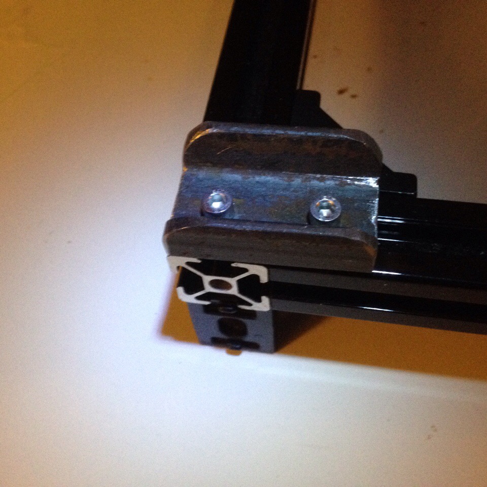
Sorry, only registered users may post in this forum.