Help me improve rigidity of frame
Posted by karandex
|
Help me improve rigidity of frame November 11, 2016 12:50AM |
Registered: 13 years ago Posts: 98 |
Hi
I am not new to building 3d printers but this is first time i am building one from aluminum extrusion
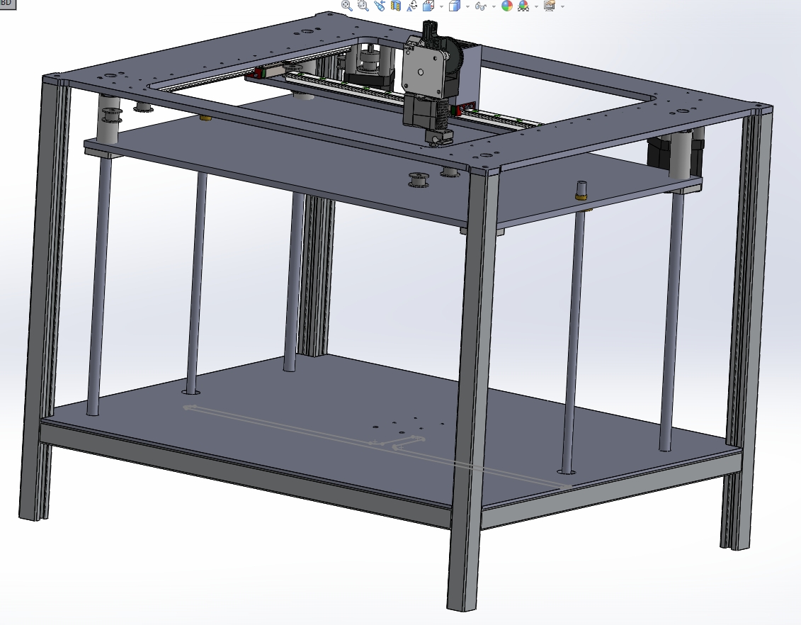
My design is inspired by 3dprinterlife elipse3dv2.
Its got top 6mm plate where mgn12 rails of length 300mm are mounted (2 for y axis and 1 for x axis)
The whole top plate is currently supported by 4 2020 extrusion. I have already build a test machine with acrylic ( that machine dont have horizontal extrusion as shown in design. Its wobbling a lot.
Top plate dimentions is coming to be 500x410mm
I have few questions
Should i go for 3030 for extrusions?
is there any other way to make this design more rigid like cross braces etc. I am expected to have panels inside the slots of extrusion to cover the sides and back , so adding truss in middle will ruin that plan which i am okey because i can always mount panels on outside with t nuts
Edited 1 time(s). Last edit at 11/11/2016 12:51AM by karandex.
I am not new to building 3d printers but this is first time i am building one from aluminum extrusion
My design is inspired by 3dprinterlife elipse3dv2.
Its got top 6mm plate where mgn12 rails of length 300mm are mounted (2 for y axis and 1 for x axis)
The whole top plate is currently supported by 4 2020 extrusion. I have already build a test machine with acrylic ( that machine dont have horizontal extrusion as shown in design. Its wobbling a lot.
Top plate dimentions is coming to be 500x410mm
I have few questions
Should i go for 3030 for extrusions?
is there any other way to make this design more rigid like cross braces etc. I am expected to have panels inside the slots of extrusion to cover the sides and back , so adding truss in middle will ruin that plan which i am okey because i can always mount panels on outside with t nuts
Edited 1 time(s). Last edit at 11/11/2016 12:51AM by karandex.
|
Re: Help me improve rigidity of frame November 11, 2016 05:23AM |
Registered: 8 years ago Posts: 601 |
|
Re: Help me improve rigidity of frame November 11, 2016 09:05AM |
Registered: 7 years ago Posts: 34 |
Look up the term "gusset".
That frame can be made incredibly rigid by adding triangular gussets to each right-angle intersection. In the case of the intersection of two 2020 frame members, a gusset bolted to the outside of each intersection will add a huge amount of stiffness. These can be as simple as triangles of aluminum, bolted into the outside slots of the frame members. This leaves the inside slots for your use in the machine.
Stiffening plates for intersections are standard accessories for aluminum extrusions, and a common item in the catalogs of sellers of such extrusions.
I can do pictures if needed, but I think you will see the idea.
|
Re: Help me improve rigidity of frame November 11, 2016 07:25PM |
Registered: 11 years ago Posts: 5,780 |
Wobbling is a result of things flexing. Larger cross section members will flex less, but directly connecting the vertical members to the relatively thin top plate will probably cause the top plate to flex. Those long vertical members can apply a lot of leverage to the top plate.
I know a lot of people use it, but I think that 2020 is too small for anything but small printers. My printer is made from 1.5" 8020 type extrusions in a cubic type frame- see the link in my sig below- and it is absolutely rock solid without and bolstering of any kind. I also used fully support linear guides in the X and Y axes and fully supported round rails in the Z axis which all but eliminates flex in the rails as a source of print quality problems. The bed is a piece of 1/4" cast aluminum tooling plate supported on a three point leveling system. The whole assembly is so rigid that I do not have to relevel the bed unless I take it apart for maintenance or to make mechanical changes.
I am working on a CoreXY printer that will be made the same way- here's the XY stage that will set into the rest of the frame on a shelf that will allow it to be removed and replaced without requiring any adjustments.
I buy the 1.5" 8020 at local scrap yards for the aluminum recycling price- about $2-2.50/lb. Sometimes it has a little paint on it, sometimes holes in random places, but neither affects its performance, and it's a LOT cheaper than buying the stuff new (or buying 2020). I cut the frame members a few mm longer than needed with a band saw, then mill them square and to final matched lengths. I join the frame members by tapping the center holes and using 5/16-18 screws to hold them together. When I bolt the pieces together they form square joints without shims or other adjustment. Details of the joining technique are in the Instructable.
Ultra MegaMax Dominator 3D printer: [drmrehorst.blogspot.com]
I know a lot of people use it, but I think that 2020 is too small for anything but small printers. My printer is made from 1.5" 8020 type extrusions in a cubic type frame- see the link in my sig below- and it is absolutely rock solid without and bolstering of any kind. I also used fully support linear guides in the X and Y axes and fully supported round rails in the Z axis which all but eliminates flex in the rails as a source of print quality problems. The bed is a piece of 1/4" cast aluminum tooling plate supported on a three point leveling system. The whole assembly is so rigid that I do not have to relevel the bed unless I take it apart for maintenance or to make mechanical changes.
I am working on a CoreXY printer that will be made the same way- here's the XY stage that will set into the rest of the frame on a shelf that will allow it to be removed and replaced without requiring any adjustments.

I buy the 1.5" 8020 at local scrap yards for the aluminum recycling price- about $2-2.50/lb. Sometimes it has a little paint on it, sometimes holes in random places, but neither affects its performance, and it's a LOT cheaper than buying the stuff new (or buying 2020). I cut the frame members a few mm longer than needed with a band saw, then mill them square and to final matched lengths. I join the frame members by tapping the center holes and using 5/16-18 screws to hold them together. When I bolt the pieces together they form square joints without shims or other adjustment. Details of the joining technique are in the Instructable.
Ultra MegaMax Dominator 3D printer: [drmrehorst.blogspot.com]
|
Re: Help me improve rigidity of frame November 21, 2016 03:55PM |
Registered: 13 years ago Posts: 98 |
Thanks for the reply
I am planning to build the machine for potentially selling as a robust work horse of a 3d printer , also now looking at that most of the part are independent of the build size of the machine
[www.thingiverse.com]
I Really liked the design, but i dont get it how the rails are attached to the extrusions. There are no 4040 m3 t nuts for it.
Another one i am looking at [imgur.com]. i am only taking idea for the xy from this machine . I know i can build a good corexy with rails but the z axis is my only concern. A
I saw the livestream of tom on markforged and looking at 10mm(?) of aluminum plate as cantilever gave me quite a confidence , but i will be save and use single motor belt driven 2 leadscrew system.
|
Re: Help me improve rigidity of frame November 22, 2016 04:56AM |
Registered: 13 years ago Posts: 98 |
|
Re: Help me improve rigidity of frame December 02, 2016 10:29AM |
Registered: 8 years ago Posts: 1,671 |
|
Re: Help me improve rigidity of frame May 12, 2017 01:01PM |
Registered: 8 years ago Posts: 776 |
Quote
the_digital_dentist
Wobbling is a result of things flexing. Larger cross section members will flex less, but directly connecting the vertical members to the relatively thin top plate will probably cause the top plate to flex. Those long vertical members can apply a lot of leverage to the top plate.
hiya dd good to see you're still here. i've created a page about mechanical rigidity and could really use your input, particularly links to that thing you did with the drilling of extrusion and right-angle joining it. karandex, i used your post as one of the examples, it's a really good question, hope you don't mind.
[reprap.org]
help and extra sections in there welcomed. does anyone remember that all-aluminum design of bed support, with quad bearing blocks mounted to an L-shaped plate? i so can't remember where i saw it.
Sorry, only registered users may post in this forum.