Riki200
Posted by lkcl
|
Re: Riki200 August 05, 2017 09:45AM |
Registered: 8 years ago Posts: 776 |
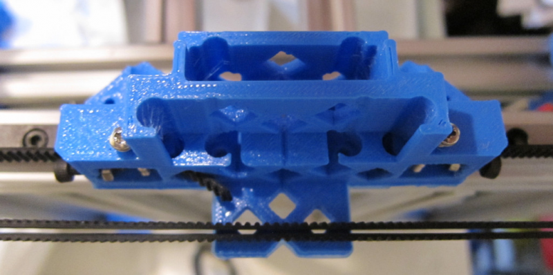
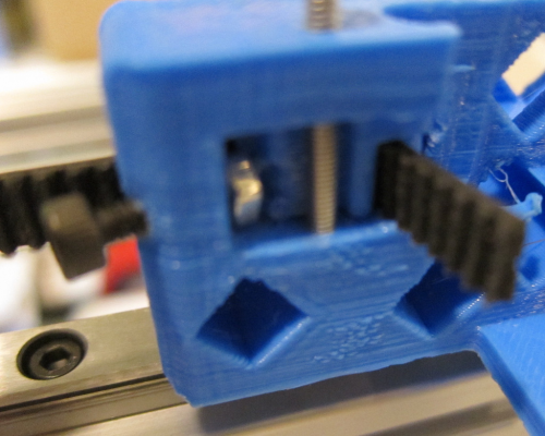
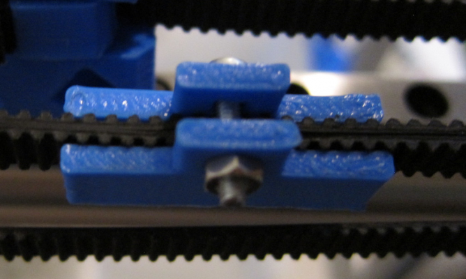
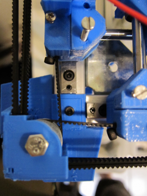
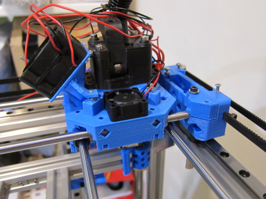
ok so after some experimentation - bear in mind that this is an interim design so that i can get up-and-running printing PETG and PC parts - i settled on a belt attachment system that is adjustable at both ends.
the reason for double-end adjustment is after the comments (gratefully received) about how hard it would be to align this type of design, where there are FOUR belt ends to align (per belt!) each of which truly matters as far as ensuring that the *pair* of belts per axis are both properly tensioned and also aligned.
also the belt clamp, which is a very simple affair (and also light-weight but also long, to ensure minimum belt wobble) does not contain teeth on one side, again so as to permit the two belts to not be forcibly-aligned only on 2mm (one tooth) boundaries. clamping the belt down hard is sufficient to keep them stuck together and not move. the extra length on the belt clamp is required because the "pull" is, being on one belt only, actually slightly off centre-of-gravity of the combined two belts. therefore there is a small amount of "twist" which is minimised by having the clamp be longer. it's quite obvious when the belts are slack: i'm hoping that under tension the "twist" doesn't occur.
this is quite a high-risk design to be honest: i'm not totally happy with it. but i need something operational and this was the simplest option that gets "something working from where the design was at the first phase which didn't work".
|
Re: Riki200 first print! August 09, 2017 02:12AM |
Registered: 8 years ago Posts: 776 |
first print that's worthy of the name, with a LOT of calibration still to be done and also without a cooling fan holder. i suspect the blobs are where there is no "ooze retract" yet properly calibrated: the blobs are at the exact points where each layer begins. the slight bowing is down to there being no cooling fanholder, and the stringing effect on the top layer is because i haven't yet worked out how to configure skeinforge to slow down on doing the top layers.
in all however i am delighted and relieved that this can now be considered to be a 'working' printer.
in all however i am delighted and relieved that this can now be considered to be a 'working' printer.
|
Re: Riki200 August 09, 2017 02:19AM |
Registered: 8 years ago Posts: 776 |
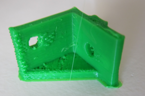
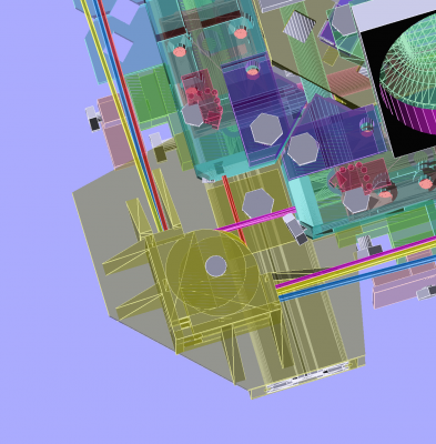
this is where i made a mistake in the right idler corner. i have the CAD simulation "perfect".... but i had used 1mm belt thicknesses. also i had misaligned the bearings by something like 0.5mm placement, so no wonder it came out like this. *fortunately* it merely causes belt-stretch, it's *not* on the critical path (from the drive motor). the drive motor side *is* correctly at right-angles, thank goodness.
i may have to fine-tune this a bit, adjust by about 0.5mm - belts to the motor pulleys are actually okay: it's the idlers that aren't.
i may have to fine-tune this a bit, adjust by about 0.5mm - belts to the motor pulleys are actually okay: it's the idlers that aren't.
|
Re: Riki200 August 09, 2017 02:26AM |
Registered: 8 years ago Posts: 776 |
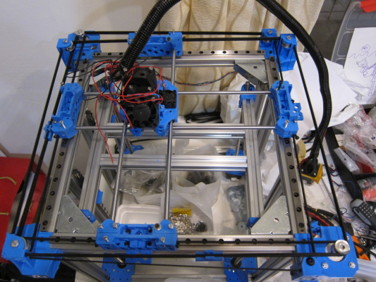
here's a top view showing the complete layout. the black tube is the flex3drive's flexible driveshaft (850mm), and it's a G2 variant from a couple years ago.
just showing how things fit together. the x and y ends are chamfered so that they fit together even in the corners
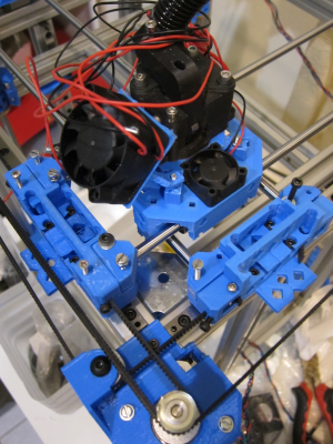
showing the carriage and in particular the fanholder for the extruder. the only way that was even possible to create was because of pyopenscad, polysurface and the spline-curve generator i used. starting from a circle i progressively added rectangles of different sizes and placed them at different angles, to get the airflow directed down to the extruder. it can fit down through a gap that's 25mm x 20mm and it bends about 60 degrees just at the end.
to do that in any other CAD system would be... hell. with a pyopenscad and supporting libraries it's done in about 50 lines of code.
|
Re: Riki200 August 09, 2017 09:33AM |
Registered: 11 years ago Posts: 5,780 |
It's always satisfying to get that first print off a new machine. First prints always look like crap because we want to see it print and can't wait until everything is tweaked... Besides, how else would we know what has to be tweaked? I'm sure you'll get it tuned up.
Ultra MegaMax Dominator 3D printer: [drmrehorst.blogspot.com]
Ultra MegaMax Dominator 3D printer: [drmrehorst.blogspot.com]
|
Re: Riki200 August 09, 2017 09:52AM |
Registered: 8 years ago Posts: 776 |
Quote
the_digital_dentist
It's always satisfying to get that first print off a new machine. First prints always look like crap because we want to see it print and can't wait until everything is tweaked... Besides, how else would we know what has to be tweaked? I'm sure you'll get it tuned up.
thanks dd. the one with the z-height set like crap went in the bin...

oh - that was at.... 150mm/sec btw. it's a small part, so wouldn't be totally at that speed. main focus has to be the cooling fan.
what absolutely amazes me though is how quiet this thing is! the noisiest bit is the twin 40mm fans for the hotend. do you know of any better (quieter but powerful) fans / blowers by any chance? i could go up to 50mm but it has to be crunched down through a space 25 x 20mm to get access to the E3Dv6 circular vanes
|
Re: Riki200 August 10, 2017 10:05AM |
Registered: 8 years ago Posts: 776 |
daiyhm, after the taobao clone rattling backwards and forwards making a godawful racket, i left the room briefly, came back and thought, "argh! ohnoo! the 3hr print job's stopped!" but nooo it was just too quiet to notice  although.... in this video it doesn't seem that way, the twin 40mm fans must have some sort of resonance that the microphone picks up
[youtu.be]
 although.... in this video it doesn't seem that way, the twin 40mm fans must have some sort of resonance that the microphone picks up
[youtu.be]
|
Re: Riki200 August 11, 2017 07:00AM |
Registered: 8 years ago Posts: 776 |
[youtu.be]
quick video showing the new cooling fan duct, which takes *twin* 25mm fans at the *top* of the carriage, and is shaped like a pair of trousers for a really fat alien the "legs" merge together into a ring, similar to the mendel90 fan duct. it was supposed to be designed for not needing any support whilst printing, but some of the angles are around 70 degrees, which is just a bit too much. manual support which can be snapped off has done the trick.
quick video showing the new cooling fan duct, which takes *twin* 25mm fans at the *top* of the carriage, and is shaped like a pair of trousers for a really fat alien
 the "legs" merge together into a ring, similar to the mendel90 fan duct. it was supposed to be designed for not needing any support whilst printing, but some of the angles are around 70 degrees, which is just a bit too much. manual support which can be snapped off has done the trick.
|
Re: Riki200 August 12, 2017 07:02PM |
Registered: 6 years ago Posts: 90 |
Looks like we're on the same track (kinda), but you're much further along than I am.
[forums.reprap.org]
Edited 1 time(s). Last edit at 08/12/2017 07:10PM by gtj.
[forums.reprap.org]
Edited 1 time(s). Last edit at 08/12/2017 07:10PM by gtj.
|
Re: Riki200 August 13, 2017 02:15AM |
Registered: 8 years ago Posts: 776 |
Quote
gtj
Looks like we're on the same track (kinda), but you're much further along than I am.
[forums.reprap.org]
ooo i reaallly wanted to use carbon-fibre rods, keeps weight down. but bear in mind they're definitely not "precision made". when i looked at that i was going to use i think it was... 8 mm solid carbon fibre (it's easy to get hold of) and create some tiny Polycarbonate V-rollers with 6x3x2.5mm twin bearings in them, 3 per rod, one of them spring-loaded to create the required tension without needing precision tolerance. this i can still do as an upgrade later on what i've already got here.
i'm not really further along.... it's just that i have to have a working intermediary
 i'll be converting over to ultimaker-style as well... *sigh*....
|
Re: Riki200 August 13, 2017 03:27AM |
Registered: 8 years ago Posts: 776 |
whoops put this under the wrong topic! 
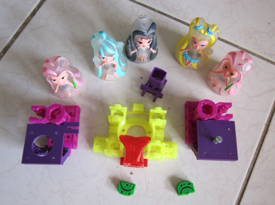
so those are light-sprites at the top (of course)... the main carriage (yellow) is PETG after a bad experience with a fan failure ended up melting the extruder... *sigh*... the part-cooling fan is also in PETG (red) as it will be a little bit close to the printbed. the fan ducts are all done with pyopenscad / polysurface, spec'd out with simple one-liner functions to create circles (or squares) as required, then passed to the spline-generating function (another one-liner).
still TBP: the z rod end holders and the y idler. at some point i will replace *all* the parts so that this can be sold as a (verified!!!) kit from HK/Taiwan/China-sourced parts.
Edited 1 time(s). Last edit at 08/13/2017 03:44AM by lkcl.
|
Re: Riki200 August 14, 2017 06:30AM |
Registered: 8 years ago Posts: 776 |
okaaay deep breath time: the double-back-to-back belts idea is a bust (a recoverable one, but still a bust).
basically what happens is that round say a 625 bearing the first belt is travelling say 90 degrees on a diameter of 8mm, that means pi/2 * 8mm of travel, but the second belt back-to-back with it, which is at appx *9.5* mm due to the 1st belt being approx 1.5mm thick, tries to travel pi/2 * 9.5mm *for the same change in angle*. that's not so much of a problem for the idlers but for the GT2 gears it's a *massive* problem.
so what happens is that the inner belt goes slack as it is "pulled" too far round by the outer belt. now, this could be solved in a couple of ways:
(1) slacken off the outer belt. not an option
(2) put silicon spray or oil on the backs of the belts so that they slide round corners. not keen on this.
(3) add extra bearings which take the outer belt, offset by 1.5mm from the inner, so that the outer belt remains completely parallel:
so, green idlers are slightly offset from black (by thickness of belt). red is the belt clamp.
now, the thing is: this adds *four* extra bearings (two per axis), is another redesign of what is in effect an intermediary design, so i'm going to call this one a day, use it (as it does actually work) to print the parts for the next one, which will be ultimaker-style just like yours, gtj.
|
Re: Riki200 August 15, 2017 03:44AM |
Registered: 8 years ago Posts: 5,232 |
WOW 
That would be a deep fall from a uniquely ( still overly complex IMHO ) design to a well aged Ultimaker design. I guess, you won't go the carbon rod route, like gtj?
Are you really sure, there is no other way to save the clamped dual belt-design? What if you place the two belts on top of each other?
( Actually I got confused how the belts are routed now, after all these sketches )
|
Re: Riki200 August 15, 2017 03:56AM |
Registered: 8 years ago Posts: 776 |
Quote
o_lampe
WOW
That would be a deep fall from a uniquely ( still overly complex IMHO ) design to a well aged Ultimaker design.
not quite: i still want to use pulleys, to halve the tension on the belt. it is better to find out why you *don't* do things a certain way.
Quote
I guess, you won't go the carbon rod route, like gtj?
later, yes - i really want to try that out.
Quote
Are you really sure, there is no other way to save the clamped dual belt-design?
yes.... by using benson's original approach:
Quote
What if you place the two belts on top of each other?
then that would mean having to use an intermediary closed-loop belt (just as in the original etch-a-sketch) or to have dual GT2-6 drivegears per motor shaft. which makes me nervous as the NEMA17 drive shafts are short for a reason.
plus the interlacing would be quite complex - doable but i've had enough of it. the belt lengths are also not symmetric, and you still get the clamp rotating by about 5 degrees, even when it's 50mm long.
Quote
( Actually I got confused how the belts are routed now, after all these sketches )
 basically as in benson's sketch except without those "outrigger" bearings for the outer belt. that was... a mistake.
so.... onwards....
|
Re: Riki200 August 15, 2017 09:38AM |
Registered: 6 years ago Posts: 90 |
|
Re: Riki200 August 16, 2017 11:02PM |
Registered: 6 years ago Posts: 14 |
Ok, started to think a bit about Benson's "Ultimaker-style" belt concept... augmented with some info I gathered from the Riki200 page.
Unfortunately I had to make some assumptions as the BOM link doesn't seem to be working (same with the other links to hands.com).
When I read about the intention to use a 40:1 gear from the NEMA17 to the rod that moves the gantry belts, I was wondering whether the motors can keep up with the speed required to be able to print fast enough - also since stepper motors lose torque at higher speeds (see e.g. page 2 of this NEMA17 datasheet.
So I created a little calculator and pre-filled it with the numbers I could come up with from the information I gathered.
Note that I didn't even put in the 40:1 gear ratio but left it as 2:1 to account for just the pulley arrangement proposed by Benson being driven directly by the motor.
Still, the results are, for the proposed 400mm/s print speed, a rather staggering 1200RPM for the motor, which (in the PDF above) suggests, at best and at the proposed 24V, a torque of only ~44% of the holding torque (which is already lower than the 2:1 gain obtained by the pulley arrangement itself).
Keep in mind that I am by no means an expert and may also have errors in my calculator, so please let me know if you find bugs or other errors in this line of reasoning. I also have to admit that I am a little confused by the torque/speed plots on that PDF as they start out at way lower numbers than the Holding Torque numbers given in the table on page 1.
Edited 1 time(s). Last edit at 08/16/2017 11:05PM by chrigel.
|
Re: Riki200 August 17, 2017 01:50AM |
Registered: 8 years ago Posts: 776 |
Quote
chrigel
Ok, started to think a bit about Benson's "Ultimaker-style" belt concept... augmented with some info I gathered from the Riki200 page.
Unfortunately I had to make some assumptions as the BOM link doesn't seem to be working (same with the other links to hands.com).
ha - let's fix that....
Quote
When I read about the intention to use a 40:1 gear from the NEMA17 to the rod that moves the gantry belts,
which isn't the case. the 40:1 wormdrive is in the flex3drive - in the extruder only.
Quote
I was wondering whether the motors can keep up with the speed required to be able to print fast enough - also since stepper motors lose torque at higher speeds (see e.g. page 2 of this NEMA17 datasheet.
So I created a little calculator and pre-filled it with the numbers I could come up with from the information I gathered.
oo nice!
Quote
Note that I didn't even put in the 40:1 gear ratio but left it as 2:1 to account for just the pulley arrangement proposed by Benson being driven directly by the motor.
Still, the results are, for the proposed 400mm/s print speed, a rather staggering 1200RPM for the motor, which (in the PDF above) suggests, at best and at the proposed 24V, a torque of only ~44% of the holding torque (which is already lower than the 2:1 gain obtained by the pulley arrangement itself).
Keep in mind that I am by no means an expert and may also have errors in my calculator, so please let me know if you find bugs or other errors in this line of reasoning. I also have to admit that I am a little confused by the torque/speed plots on that PDF as they start out at way lower numbers than the Holding Torque numbers given in the table on page 1.
ok so the actual numbers to use are:
* 400 steps/rev (0.9 deg) steppers
* 1.68A motors ( i think these are 44oz.in ones: i got the highest torque 0.9deg NEMA17s possible) spec OK42STH38-1684MA
* 20T-40T closed loop belt providing 2:1 gearing
* 2:1 pulley ratio
so that's *four* to one gearing total. which at 2400mm/sec exceeds the maximum speed listed on the graphs. hmmm.... that's bad.
soOoo.... from what you're saying, it would appear that the 2:1 pulley ratio *and* 20T-40T gearing is not a good idea. hmmm....well, i do have some 84oz.in 2A 200 steps/rev (1.8 deg) steppers i could try out if things do get hairy, but it does sound like i need to cut the pulleys. in theory i could do direct-drive (5mm coupling) of the NEMA17s to the planned 400mm long 5mm shaft but that means it sticks out an awful long way, meaning a lot of plastic a heck of a long way away from rigid metal.
ok - thank you chrigel. i'm... relieved someone's paying attention

|
Re: Riki200 August 17, 2017 03:22AM |
Registered: 6 years ago Posts: 14 |
Quote
lkcl
Quote
chrigel
When I read about the intention to use a 40:1 gear from the NEMA17 to the rod that moves the gantry belts,
which isn't the case. the 40:1 wormdrive is in the flex3drive - in the extruder only.
So I misunderstood the highlighted part of that page?
Quote
http://reprap.org/wiki/Riki200
Concept 3
The concept here is to use twin belts per axis with 340mm 5mm OD rods connecting the two, in a "standard" industrial layout. However a pulley system is to be introduced which will halve the force per belt section as well as double the accuracy. A 40:1 GT2 gear on the 5mm rod will also be deployed along with a closed loop belt, to give extra accuracy.
...or should this read "A 40:20 = 2:1 GT2 gear on the 5mm rod"?
Quote
lkcl
ok so the actual numbers to use are:
* 400 steps/rev (0.9 deg) steppers
* 1.68A motors ( i think these are 44oz.in ones: i got the highest torque 0.9deg NEMA17s possible) spec OK42STH38-1684MA
* 20T-40T closed loop belt providing 2:1 gearing
* 2:1 pulley ratio
so that's *four* to one gearing total. which at 2400mm/sec exceeds the maximum speed listed on the graphs. hmmm.... that's bad.
Thanks, I updated the calculator. You probably meant 2400RPM instead of 2400mm/sec there.
Any chance we could get links to the motor datasheet and the 20T-40T gearing you're looking at? A quick search on the web didn't bring up anything useful... or I should probably just wait until you fix that BOM link.
Quote
lkcl
[snip]it does sound like i need to cut the pulleys. in theory i could do direct-drive (5mm coupling) of the NEMA17s to the planned 400mm long 5mm shaft but that means it sticks out an awful long way, meaning a lot of plastic a heck of a long way away from rigid metal.
Sorry for the noob question, but what do you mean by "direct-drive (5mm coupling)"? Couldn't the motor driving the rod sit more or less centered between the two belts driven by the rod? Such as:
pulley-to-gantry-belt
         |
         |
         |
         |
       gear/belt+pulley
         |       |
         |     motor
         |     motor
         |
pulley-to-gantry-belt
Quote
lkcl
ok - thank you chrigel. i'm... relieved someone's paying attention
Glad to be helpful, I find this a very interesting project - partly because I'm one of your future customers

Edited 2 time(s). Last edit at 08/17/2017 03:28AM by chrigel.
|
Re: Riki200 August 17, 2017 03:35AM |
Registered: 6 years ago Posts: 14 |
|
Re: Riki200 August 17, 2017 03:38AM |
Registered: 8 years ago Posts: 776 |
Quote
chrigel
...or should this read "A 40:20 = 2:1 GT2 gear on the 5mm rod"?
yes. you want to edit it?
Quote
Thanks, I updated the calculator. You probably meant 2400RPM instead of 2400mm/sec there.
Any chance we could get links to the motor datasheet and the 20T-40T gearing you're looking at? A quick search on the web didn't bring up anything useful... or I should probably just wait until you fix that BOM link.
should be done.... except i haven't run "make" yet - it takes a hell of a long time. best to be honest is if you do a git clone of the repository. what you're asking for is auto-generated output (at a later stage of the project) - i cloned a previous project, that's why the links are in there in the first place.
datasheet: pffh. china spec'd motor
 *might* be possible to find it from that P/N. if you do let me know, i'll add it to the python source.
Quote
Sorry for the noob question, but what do you mean by "direct-drive (5mm coupling)"? Couldn't the motor driving the rod sit more or less centered between the two belts driven by the rod? Such as:
a motor cannot sit in the middle of the rod and be direct-drive unless the rod is going right through the *middle* of the motor. i.e. the motor has a 200mm shaft coming out the back and a 200mm long shaft coming out the front.
google "5mm coupling nema 17" and you'll find it.
Quote
Glad to be helpful, I find this a very interesting project - partly because I'm one of your future customers
ha, cool

|
Re: Riki200 August 17, 2017 04:03AM |
Registered: 8 years ago Posts: 776 |
Quote
chrigel
Instead of removing the pulley system, couldn't you choose a 1:1 gearing (if available)? That way we'd keep the advantage of the belt tension being halved.
yehyeh i was just mulling that idea over. the main thing is, i wanted people to be able to do high-accuracy with this design as well, meaning the possibility of running at much slower speeds, using e.g. 0.15mm E3D experimental nozzles, where you actually start to get artefacts from micro-stepping showing up in the print if you have a 1:1 ratio.
i think you're right, chrigel: just dropping in a pair of GT2-6mm-20T gears, one on the motor and one on the pulley, keeping the closed-loop belt, would do the trick.
the only thing that concerns me is, there's going to be one hell of a lot of force on the bearings (and the plastic holding them), so i might have to follow the_digital_dentist's advice and use a solid block to hold the bearings that the 400mm long 5mm rod goes through.
i'll also need to put the motor on an adjustable "thing" otherwise if people swap out GT2-6mm-40T for GT2-6mm-20T they'd have to use a different length closed-loop belt.
|
Re: Riki200 August 17, 2017 08:50AM |
Registered: 8 years ago Posts: 776 |
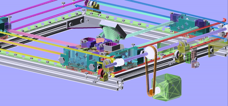
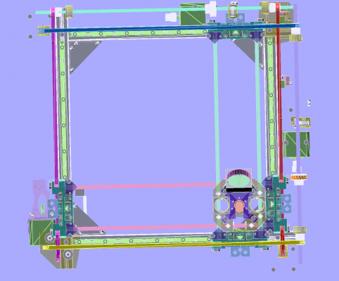
ok so this is interlacing belts with pulleys on the x/y-ends. i've moved the motors to 1/3 the way along the rods so that they can be attached on a sliding gantry to the z-uprights for the printbed. that way the GT2-6mm-40T could be replaced with a GT2-6mm-20T.
the belt interlacing is very very specific and there is about 1.5mm clearance in places. i've also turned the frame through 90 degrees so that the attachment points, some of which were quite a long way away from metal, now have metal support underneath them within around 25mm or less. the 5mm rods themselves will also help stop any plastic twisting.
sooo.... i'm reasonably happy with the belt, pulley and rod positioning: now it's just a matter of filling in the 3D-printed parts....
|
Re: Riki200 August 18, 2017 02:25AM |
Registered: 6 years ago Posts: 14 |
About the 1:1 gear option:
Wow, that's fantastic. You know, I am more and more looking forward to owning this printer myself ...really appreciate your efforts to make it as versatile and capable as possible!
Yes, that's what I was trying to illustrate with my crappy ASCII graphic above... sorry, should've been more clear. Judging from your last screenshot, I see you're also still planning to implement the 2:1 pulley system proposed by Benson for the gantry belts. Great you can use the vertical printbed's z-uprights for fixing the motors at adjustable distances.
Here are some of my thoughts on this topic:
The top shows your current belt layout (at least as I understand it), the bottom shows an alternative. Left are the front, right the side views of the layouts.
So... if we could shift the belt planes out of the frame so they don't intersect the gantry rails, I think this could have the following mechanical advantages:
Now for the disadvantages:
3. Increased printer volume due to extending rods past the frame and the gantry belts running outside the frame rather than on top.
4. The gantry belts now have to have their fixed end points outside the frame as well (see point C).
I think your genius way of interlacing the belts should still be possible with this variant...
Edited 1 time(s). Last edit at 08/18/2017 02:33AM by chrigel.
Quote
lkcl
[...] the main thing is, i wanted people to be able to do high-accuracy with this design as well, meaning the possibility of running at much slower speeds, using e.g. 0.15mm E3D experimental nozzles, where you actually start to get artefacts from micro-stepping showing up in the print if you have a 1:1 ratio.
Wow, that's fantastic. You know, I am more and more looking forward to owning this printer myself
 ...really appreciate your efforts to make it as versatile and capable as possible!
Quote
lkcl
i think you're right, chrigel: just dropping in a pair of GT2-6mm-20T gears, one on the motor and one on the pulley, keeping the closed-loop belt, would do the trick.
Yes, that's what I was trying to illustrate with my crappy ASCII graphic above... sorry, should've been more clear. Judging from your last screenshot, I see you're also still planning to implement the 2:1 pulley system proposed by Benson for the gantry belts. Great you can use the vertical printbed's z-uprights for fixing the motors at adjustable distances.
Quote
lkcl
the only thing that concerns me is, there's going to be one hell of a lot of force on the bearings (and the plastic holding them), so i might have to follow the_digital_dentist's advice and use a solid block to hold the bearings that the 400mm long 5mm rod goes through.
Here are some of my thoughts on this topic:
The top shows your current belt layout (at least as I understand it), the bottom shows an alternative. Left are the front, right the side views of the layouts.
So... if we could shift the belt planes out of the frame so they don't intersect the gantry rails, I think this could have the following mechanical advantages:
- Since the z-position of the gantry rods is now limited by the rod itself and not its pulley diameter, it can be lower (compare measurements A and B ). This allows the yellow and green printed plastic parts to be reduced in height.
- By having the motor-driven, 400mm long 5mm rod now being positioned *below* the plane of the gantry rods, we get the following effects:
- Even more reduction of the green parts' height.
- The main force of the gantry belt tension can now be absorbed by compressing the green parts against the 2020 aluminium frame rather than by flexing green "towers" (compare forces D and F).
- The top of the green "towers" now only have to withstand 1x belt tension instead of 2x (compare belt forces at points D and E).
Now for the disadvantages:
3. Increased printer volume due to extending rods past the frame and the gantry belts running outside the frame rather than on top.
4. The gantry belts now have to have their fixed end points outside the frame as well (see point C).
I think your genius way of interlacing the belts should still be possible with this variant...
Edited 1 time(s). Last edit at 08/18/2017 02:33AM by chrigel.
|
Re: Riki200 August 18, 2017 03:01AM |
Registered: 8 years ago Posts: 776 |
Quote
chrigel
Wow, that's fantastic. You know, I am more and more looking forward to owning this printer myself...really appreciate your efforts to make it as versatile and capable as possible!
well it's more by accident than by design - often the way it goes, y'know?

Quote
Yes, that's what I was trying to illustrate with my crappy ASCII graphic above... sorry, should've been more clear. Judging from your last screenshot, I see you're also still planning to implement the 2:1 pulley system proposed by Benson for the gantry belts. Great you can use the vertical printbed's z-uprights for fixing the motors at adjustable distances.
yes, keeping the pulley system... partly because i've already done the x/y-end design, but also because you reminded me that there's less belt tension per segment under load.
Quote
Here are some of my thoughts on this topic:
The top shows your current belt layout (at least as I understand it), the bottom shows an alternative. Left are the front, right the side views of the layouts.
So... if we could shift the belt planes out of the frame so they don't intersect the gantry rails, I think this could have the following mechanical advantages:
i'm already using both those layouts. to interlace the belts the planes have to be inverted relative to each other in a very specific way.
ok so here's a top photo: you can see that the belts are mostly not intersecting the gantry rails, with the exception being at the ends. i did a video as well (at the end) to show you, it's *very* specific.
also, you can't reduce the height of the x/y-ends because they have to take (and clamp) the x and y carriage rods... which are slightly offset (12mm). the pulley bearings are *also* offset (by appx... 14mm) and so what i've done, to make sure that there's plastic behind each, is inverted them. so, x-end the pulley bearings are low and the carriage rods (and their clamps) are high, and the y-end it's the opposite way round.
Quote
Now for the disadvantages:
3. Increased printer volume due to extending rods past the frame and the gantry belts running outside the frame rather than on top.
4. The gantry belts now have to have their fixed end points outside the frame as well (see point C).
I think your genius way of interlacing the belts should still be possible with this variant...
genius?? pffh. persistence and a blithe willingness to proceed without checking what i'm doing in advance?? is that what it's called these days?
 no, it's not really genius: there's a certain way that the physical limitations can be achieved, and that defines where to go from there.
anyway: the rods and gantry belts are already well outside the frame. by something like 40mm in places. that's why i made the frame-top like a table side-view (or the symbol for pi with a lower cross-brace added), so that there's bits of gantry that can be used to stabilise the "outrigger" corner-pieces for the idler bearings (etc.)
[youtu.be]
|
Re: Riki200 August 18, 2017 03:57AM |
Registered: 6 years ago Posts: 14 |
Quote
lkcl
i'm already using both those layouts. to interlace the belts the planes have to be inverted relative to each other in a very specific way.
ok so here's a top photo: you can see that the belts are mostly not intersecting the gantry rails, with the exception being at the ends. i did a video as well (at the end) to show you, it's *very* specific.
[snip]
[youtu.be]
Wow, you're quick... thanks a lot for the video explainer, I wouldn't have seen how specific and complicated all the corners really are! Have to think about that one, so far I am still not 100% convinced you couldn't do *both* belts as the "inverted" belt layout - but I do trust your judgement as you're the one who has the 3D simulation in front of you
 ...I guess I'll have to watch the video a couple of times more
  ...really appreciated.
|
Re: Riki200 August 18, 2017 03:59AM |
Registered: 6 years ago Posts: 14 |
|
Re: Riki200 August 18, 2017 04:23AM |
Registered: 8 years ago Posts: 776 |
Quote
chrigel
Wow, you're quick...
just happened to wake up at the right time...

Quote
thanks a lot for the video explainer, I wouldn't have seen how specific and complicated all the corners really are! Have to think about that one, so far I am still not 100% convinced you couldn't do *both* belts as the "inverted" belt layout - but I do trust your judgement as you're the one who has the 3D simulation in front of you...I guess I'll have to watch the video a couple of times more
...really appreciated.
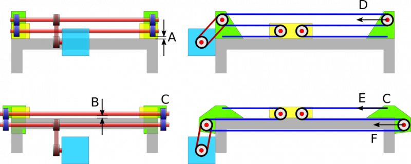
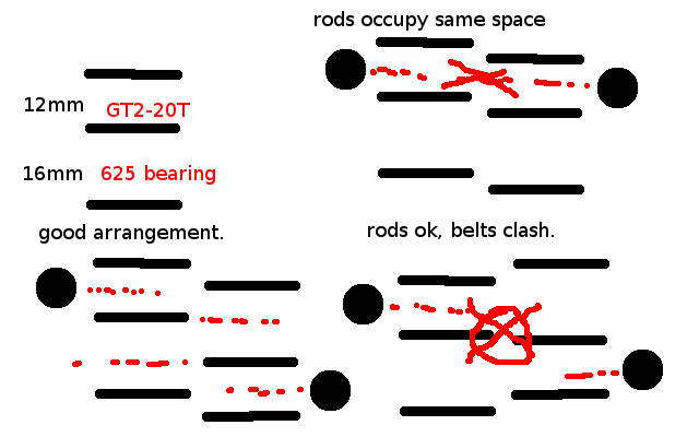
no problem. this should help. top left shows the belt separation: 12mm for the GT2-6mm-20T, 16mm for the 625 bearing. so it's *not* symmetrical. top right: if you don't invert one of them then the x and y rods try to occupy the same physical space. so you *must* offset them.
bottom left: good arrangement. one belt is inverted, the 12mm spacing fits in between the 16mm spacing of the other, and the x and y rods are offset by about... 14mm.
bottom right: BAD arrangement. one belt is inverted and LIFTED rather than LOWERED, such that the MIDDLE section of EACH belt tries to occupy the same physical space.
the ONLY reason this happens is because of the asymmetrical size of the GT2-20T and the 625 bearing. if i used a 20T idler @ 12mm it would not be a problem. but i am using 625 bearings because they cost less than dedicated idlers, and there's quite a few of them (8 - 2 on each of the 4 x/y-ends).
|
Re: Riki200 August 18, 2017 09:02AM |
Registered: 6 years ago Posts: 90 |
Quote
lkcl
* 400 steps/rev (0.9 deg) steppers
* 1.68A motors ( i think these are 44oz.in ones: i got the highest torque 0.9deg NEMA17s possible) spec OK42STH38-1684MA
ok - thank you chrigel. i'm... relieved someone's paying attention
I'm paying attention.

I've been on the hunt for for the same stepper except with dual shafts but the only ones I can find are these...
[www.digikey.com]
$60 US though. I may have to do the offset stepper with the short belt as well although I've been looking for a set of zero-backlash bevel gears to avoid the extra belt. No luck so far.
|
Re: Riki200 August 18, 2017 10:38AM |
Registered: 8 years ago Posts: 776 |
Quote
gtj
I'm paying attention.
I've been on the hunt for for the same stepper except with dual shafts but the only ones I can find are these...
[www.digikey.com]
$60 US though. I may have to do the offset stepper with the short belt as well although I've been looking for a set of zero-backlash bevel gears to avoid the extra belt. No luck so far.
yehyeh now you know why people use couplers. much cheaper to use standard off-the-shelf steppers. btw take a look on omcstepperonline's web site, they do actually have datasheets iirc.
|
Re: Riki200 August 19, 2017 02:29AM |
Registered: 8 years ago Posts: 5,232 |
Hmmm, I still don't get the argument for the Benson belt gear reduction?
You want to use it to reduce belt tension, but at the same time the belt is longer. Where do you see an advantage? Belt stretch would be the same, right?
The additional idlers don't improve matters either.
To increase steps/mm for better accuracy, you can simply use a pulley gear reduction between stepper and rod.
Edited 1 time(s). Last edit at 08/19/2017 02:30AM by o_lampe.
Sorry, only registered users may post in this forum.
