Riki200
Posted by lkcl
|
Re: Riki200 August 19, 2017 05:23AM |
Registered: 8 years ago Posts: 776 |
Quote
o_lampe
Hmmm, I still don't get the argument for the Benson belt gear reduction?
You want to use it to reduce belt tension, but at the same time the belt is longer. Where do you see an advantage? Belt stretch would be the same, right?
yes, sorry, i keep saying "belt tension" but it's actually only under acceleration that that really matters. force on the belt (producing stretch) is proportional to acceleration, and acceleration is proprtional to the square-root of the speed. physics equations: "v^2 = u^2 + 2 a s" and "F=ma"
but not only that, you now have *two* belt segments to take up the load,
hmm ok so let's go through it.
scenario 1: 1 belt, travel speed 100mm/sec, head acceleration target 3000 mm /sec.
belt acceleration is directly proportional, belt undergoes acceleration of 3000 mm / sec.
scenario 2: 1-pulley belt, same targets.
consider one belt. belt now does 200 mm / sec for the 100 mm / sec target. corresponding belt acceleration goes up FOUR fold but the mass is HALVED (because it's shared over 2 pulleys).
therefore acceleration force on the whole belt is DOUBLED compared to a no-pulley scenario.
is that actually right??
Quote
The additional idlers don't improve matters either.
yes you're correct about that: there's an awesome post by someone with a telephone number for a userid on here, i'll try to find it... ah! got it! [forums.reprap.org]
here he describes how if you're using rubbish-for-idlers the amount of "play" which introduces tolerance inaccuracies can really *really* add up.
Quote
To increase steps/mm for better accuracy, you can simply use a pulley gear reduction between stepper and rod.
indeed. damn. damn damn damn. well, i've got a pulley system in place so that's ok, but damnit i'm half-way through the pulley design.
need some help here. i think what i'll do is ask on a physics forum if the assessment above is correct. EDIT: [physics.stackexchange.com] let's see what happens....
Edited 1 time(s). Last edit at 08/19/2017 05:37AM by lkcl.
|
Re: Riki200 August 19, 2017 08:25AM |
Registered: 8 years ago Posts: 776 |
well... what happened was we had some blithering idiot get stroppy because i don't have a high enough reputation to insert images into questions. rather than ask questions which would be useful he simply dived in with a -1 moderation. so *sigh* i've been forced into the stupid position of DELETING the question and asking it a second time. [physics.stackexchange.com]
|
Re: Riki200 August 19, 2017 09:04AM |
Registered: 6 years ago Posts: 6 |
Sure. But I'm not sure why we're calculating belt acceleration. As long as the belt's mass is small compared to the mechanical parts, it doesn't matter much.Quote
lkcl
scenario 1: 1 belt, travel speed 100mm/sec, head acceleration target 3000 mm /sec.
belt acceleration is directly proportional, belt undergoes acceleration of 3000 mm / sec.
Tension due to print-head and gantries:
Let's assign an effective mass of 1kg. We're looking at a worst case where the print head is all the way over to one side, so accelerating it falls entirely on one belt, while the two belts share the load of accelerating the gantry; thus this effective mass represents the print-head mass plus half the X (or Y) gantry mass; if you have actual numbers for this, multiply the result...
For a mass of 1kg and an acceleration of 3m/s/s, the total force on the carriage must be 3 N. Since there's only one belt segment taking the load, that segment sees a tension of 3 N, and the opposing segment has zero tension. (The top segment has either 3 N or 0, depending whether you're accelerating away from or towards the motor.)
(In reality, you probably have the belt tensioned up a bit more, so it might be 5 N in the direction of acceleration, and 2 N opposing it, or some such.)
Tension due to belt mass:
(Note: I'm consistently using "top" to refer to the long segment that goes the whole way across -- even though you actually have this on top for one axis, and on the bottom for the other.)
I'm having trouble finding a mass per unit length figure for 2mm pitch GT2 belts; I did find 8mm pitch, 12mm wide belts are 0.057 kg/m, so we could guess 1/8 of that (1/4 thickness, 1/2 width), or 0.015 kg/m. I'm gonna guess at some belt lengths here... call the "top" segment 0.5m (0.008 kg), and the sum of the "lower" segments 0.4m (0.006 kg); for the pulley case, the "middle" segments would also sum to 0.4m (0.006 kg).
Then since both the bottom segments of the belt are accelerating with the carriage, and the top segments are accelerating the same rate in the opposite direction, we have an additional 0.014 kg at 3m/s/s, for an extra 0.042 N of force -- see, negligible!
Agreed on belt speed, but I don't understand where you're coming up with acceleration; it seems like it should be double. But anyway, belt acceleration doesn't matter. Repeating the above...Quote
scenario 2: 1-pulley belt, same targets.
consider one belt. belt now does 200 mm / sec for the 100 mm / sec target. corresponding belt acceleration goes up FOUR fold but the mass is HALVED (because it's shared over 2 pulleys).
Tension due to print-head and gantries:
Effective mass of 1kg, again. For an acceleration of 3m/s/s, the total force on the carriage must still be 3 N. Since there's now two belt segments sharing the load, each segment now sees a tension of 1.5 N, and the opposing segments have zero tension. (Like before, the "top" segment has either 1.5N or 0, depending whether you're accelerating away from or towards the motor.)
Tension due to belt mass:
We've now got three segments/pairs of segments. The "bottom" segments, being fixed to the frame, are not accelerating at all. The middle segments, as before, are accelerating in the same direction as the carriage, only now accelerating twice as fast; the "top" segment is accelerating in the opposite direction, and likewise twice the acceleration. So we have the same 0.014kg as before, now at 6 m/s/s, so 0.084 N -- again, this is negligible, about 5% of the 1.5 N. (And even if you're right about the 4x, still about 10%.) No need to get into that level of detail, and if we did, we'd also want to calculate the rotational inertia of the motor, shafts, pulleys -- too much work for too little difference in the result.
|
Re: Riki200 August 19, 2017 09:26AM |
Registered: 8 years ago Posts: 776 |
Quote
benson
Sure. But I'm not sure why we're calculating belt acceleration. As long as the belt's mass is small compared to the mechanical parts, it doesn't matter much.
ok, sorry, i misworded things (btw thanks for chipping in here). really i should be asking about the *force* exerted on the belt (which we may assume to be evenly distributed, all things considered).
thus F = ma, force is proportional to acceleration, and, if the print-head is accelerating that means that a *force* is exerted on the belt. so i wasn't talking about the actual acceleration of any given belt section (i.e. its velocity) i was referring to the *force* being applied by the accelerating print-head.
Quote
Tension due to print-head and gantries:
Let's assign an effective mass of 1kg. We're looking at a worst case where the print head is all the way over to one side, so accelerating it falls entirely on one belt, while the two belts share the load of accelerating the gantry; thus this effective mass represents the print-head mass plus half the X (or Y) gantry mass; if you have actual numbers for this, multiply the result...
For a mass of 1kg and an acceleration of 3m/s/s, the total force on the carriage must be 3 N. Since there's only one belt segment taking the load, that segment sees a tension of 3 N, and the opposing segment has zero tension. (The top segment has either 3 N or 0, depending whether you're accelerating away from or towards the motor.)
ah... i think you might be referring to a non-pulley system here... ah yes, section on pulley system below.
Quote
(In reality, you probably have the belt tensioned up a bit more, so it might be 5 N in the direction of acceleration, and 2 N opposing it, or some such.)
true. yes. that differential (nicely exaggerated by the 5N-2N) is what gives you the "bounce" problems you see in prints with high acceleration settings.
Quote
Tension due to belt mass:
(Note: I'm consistently using "top" to refer to the long segment that goes the whole way across -- even though you actually have this on top for one axis, and on the bottom for the other.)
I'm having trouble finding a mass per unit length figure for 2mm pitch GT2 belts; I did find 8mm pitch, 12mm wide belts are 0.057 kg/m, so we could guess 1/8 of that (1/4 thickness, 1/2 width), or 0.015 kg/m. I'm gonna guess at some belt lengths here... call the "top" segment 0.5m (0.008 kg), and the sum of the "lower" segments 0.4m (0.006 kg); for the pulley case, the "middle" segments would also sum to 0.4m (0.006 kg).
Then since both the bottom segments of the belt are accelerating with the carriage, and the top segments are accelerating the same rate in the opposite direction, we have an additional 0.014 kg at 3m/s/s, for an extra 0.042 N of force -- see, negligible!
yes - i'm ignoring actual weight of the belt. makes life a lot easier.
Quote
Agreed on belt speed, but I don't understand where you're coming up with acceleration; it seems like it should be double. But anyway, belt acceleration doesn't matter. Repeating the above...Quote
scenario 2: 1-pulley belt, same targets.
consider one belt. belt now does 200 mm / sec for the 100 mm / sec target. corresponding belt acceleration goes up FOUR fold but the mass is HALVED (because it's shared over 2 pulleys).
seems like... that's what needs to be checked.
Quote
Tension due to print-head and gantries:
Effective mass of 1kg, again. For an acceleration of 3m/s/s, the total force on the carriage must still be 3 N. Since there's now two belt segments sharing the load, each segment now sees a tension of 1.5 N, and the opposing segments have zero tension. (Like before, the "top" segment has either 1.5N or 0, depending whether you're accelerating away from or towards the motor.)
okaaay... y'know... i sorta thought it should be like that when i first thought about this. i'm really not sure why v^2 = u^2 + 2as would show a square law as opposed to a linear relationship.
Quote
Tension due to belt mass:
We've now got three segments/pairs of segments. The "bottom" segments, being fixed to the frame, are not accelerating at all. The middle segments, as before, are accelerating in the same direction as the carriage, only now accelerating twice as fast; the "top" segment is accelerating in the opposite direction, and likewise twice the acceleration. So we have the same 0.014kg as before, now at 6 m/s/s, so 0.084 N -- again, this is negligible, about 5% of the 1.5 N. (And even if you're right about the 4x, still about 10%.) No need to get into that level of detail, and if we did, we'd also want to calculate the rotational inertia of the motor, shafts, pulleys -- too much work for too little difference in the result.
again i'm ignoring belt mass as being negligeable, so that makes sense.
so, yes, the critical case is the print-head acceleration, set to be e.g. 3N, and the two segments simply... divide that up between them. so it *is* half the force (stretch) for any given speed. the actual belt's speed (the fact that some sections travel at twice the speed) doesn't come into play.
ohhh..... riiight, okaaay, so the belt's speed only comes into play if the BELT's mass is significant. THAT would be where the pulley system would have a quadruple effect, but we already concluded that the belt's mass is negligeable, so it's okay.
does that sound about right?
|
Re: Riki200 August 19, 2017 09:26AM |
Registered: 6 years ago Posts: 6 |
Aha, I finally figured out where you're getting the 4x acceleration. You're using the formula v^2 = u^2 + 2*a*s, but that's not a particularly helpful equation for understanding this; it's for considering an acceleration (a) applied over a certain distance (s). You can use it here, sure, but it's really the long way around.
First you have to figure the distance over which the acceleration occurs, or at least some relationship between this distance in the pulley vs. no-pulley case. I think you assumed they were equal, maybe? But really, in the pulley case, the acceleration happens over twice the distance. After all, if you accelerate while moving the belt the same distance, the pulley system is accelerating the print-head over half the distance, so of course the force comes out higher.
First you have to figure the distance over which the acceleration occurs, or at least some relationship between this distance in the pulley vs. no-pulley case. I think you assumed they were equal, maybe? But really, in the pulley case, the acceleration happens over twice the distance. After all, if you accelerate while moving the belt the same distance, the pulley system is accelerating the print-head over half the distance, so of course the force comes out higher.
|
Re: Riki200 August 19, 2017 09:31AM |
Registered: 6 years ago Posts: 6 |
Pretty much -- I still think it's double, not quadruple (See post I wrote at the same time as yours...), but either way, yep, that effect only matters if you care about the belt's mass.Quote
lkcl
ohhh..... riiight, okaaay, so the belt's speed only comes into play if the BELT's mass is significant. THAT would be where the pulley system would have a quadruple effect, but we already concluded that the belt's mass is negligeable, so it's okay.
does that sound about right?
|
Re: Riki200 August 19, 2017 10:14AM |
Registered: 8 years ago Posts: 776 |
Quote
benson
Pretty much -- I still think it's double, not quadruple (See post I wrote at the same time as yours...), but either way, yep, that effect only matters if you care about the belt's mass.Quote
lkcl
ohhh..... riiight, okaaay, so the belt's speed only comes into play if the BELT's mass is significant. THAT would be where the pulley system would have a quadruple effect, but we already concluded that the belt's mass is negligeable, so it's okay.
does that sound about right?
yehyeh, which we don't. the "stretch" force i think we agree though is only double [edit: halved!!
 ]. whew ok so i don't have to throw away the parts i've already printed up, or the design work done of the past week...
  thank youuu benson, really appreciated.
Edited 1 time(s). Last edit at 08/19/2017 01:20PM by lkcl.
|
Re: Riki200 August 19, 2017 02:54PM |
Registered: 6 years ago Posts: 20 |
lkcl, I don't believe your layout will work if you are really getting a mechanical advantage.
From the black and tackle wiki page Block and Tackle. Take a look at the "Mechanical Advantage" section.
"Ideal mechanical advantage correlates directly with velocity ratio. The velocity ratio of a tackle is the ratio between the velocity of the hauling line to that of the hauled load. A line with a mechanical advantage of 4 has a velocity ratio of 4:1. In other words, to raise a load at 1 metre per second, the hauling part of the rope must be pulled at 4 metres per second."
and
"The increased force produced by a tackle is offset by both the increased length of rope needed and the friction in the system. In order to raise a block and tackle with a mechanical advantage of 6 a distance of 1 metre, it is necessary to pull 6 metres of rope through the blocks"
So if you really had a mechanical advantage in your layout, in order to move the carriage 10 mm you will have to move 20 mm of belt at the drive pulley (for a 2 to 1 mechanical advantage). Where would the extra 10 mm of belt go ? Since it wraps back to the idler on the opposite side of the carriage, your carriage would become unconstrained whenever you try to move it (with the drive pulley).
You really will be much better off attaching the belts to the carriage and using a pulley gear reduction between stepper and drive rod like o_lampe suggested.
Also, why use 4 rods to carry the carriage ? Four rods just adds friction, complexity, weight and cost. You only need one rod on each axis.
|
Re: Riki200 August 19, 2017 03:56PM |
Registered: 8 years ago Posts: 776 |
Quote
xyze
lkcl, I don't believe your layout will work if you are really getting a mechanical advantage.
From the black and tackle wiki page Block and Tackle. Take a look at the "Mechanical Advantage" section.
"Ideal mechanical advantage correlates directly with velocity ratio. The velocity ratio of a tackle is the ratio between the velocity of the hauling line to that of the hauled load. A line with a mechanical advantage of 4 has a velocity ratio of 4:1. In other words, to raise a load at 1 metre per second, the hauling part of the rope must be pulled at 4 metres per second."
yes. so in this case with only a single pulley it'll be twice the speed not four times. velocity ratio of 2.
Quote
and
"The increased force produced by a tackle is offset by both the increased length of rope needed and the friction in the system.
indeed. i do not expect to be able to take full advantage of the otherwise "ideal" conditions offered by a theoretically perfect velocity ratio of 2.0
Quote
In order to raise a block and tackle with a mechanical advantage of 6 a distance of 1 metre, it is necessary to pull 6 metres of rope through the blocks"
So if you really had a mechanical advantage in your layout, in order to move the carriage 10 mm you will have to move 20 mm of belt at the drive pulley (for a 2 to 1 mechanical advantage).
correct.
Quote
Where would the extra 10 mm of belt go ?
into the pulley at the opposite end, which is going in the opposite direction. which is exactly balanced.
Quote
Since it wraps back to the idler on the opposite side of the carriage, your carriage would become unconstrained whenever you try to move it (with the drive pulley).
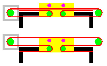
ah no, it won't. the amount by which one pulley moves produces slack that is exactly and precisely taken up by the pulley on the other end. benson's diagram helps illustrate:
ignore the top image, focus on the bottom one. you have three "levels" of belt. the top one is a fixed length. assume that left-side levels 2 and 3 are the same length (for convenience) and right-side levels 2 and 3 likewise. left side lengths plus right side lengths equals... a fixed amount. i.e. regardless of the position of the carriage, all belt segments will add up to *exactly* the same amount. the sections round the idlers won't change either.
with the total belt length being independent of the carriage *position*, there is no slack, at any time.
Quote
You really will be much better off attaching the belts to the carriage and using a pulley gear reduction between stepper and drive rod like o_lampe suggested.
well, i'm happy to experiment in order to find out (and am keeping the closed-loop pulley in place as well). what i will do is offer an option to unplug one 0.9 deg/step motor and drop in a 1.8 deg/step motor instead, and to also be able to move the belt from a GT2-6mm-40T to a GT2-6mm-20T on the same 360mm 5m OD shaft. so there will be the option to either have a 2.5:1 mechanical advantage of a pulley gear reduction (40T on the 350mm shaft, 16T on the NEMA17) *and* a 0.9 deg/step motor *AND* a 2:1 pulley velocity ratio - a whopping TEN to one mechanical advantage over standard 3D printers - or you could throw most of that out the window and go for speed, speed, speed instead, by putting in an 84 oz.in 2A 1.8 deg/step motor, use a GT2-20T on the motor and use the GT2-20T on the driveshaft, and still have a 2:1 mechanical advantage due to the pulleys.
that kind of flexibilty is something i'd really like to be able to offer people with this design.
i've completed and printed the x/y-ends, and installed the bearings. i'm almost done with 2 of the corner pieces, and will start printing those out tomorrow. 360mm 5mm OD rods, GT2-6mm-40T and 200mm closed-loop belts should be arriving next week from Shenzhen by way of Hong Kong
i want to see what happens, josef. i'm curious. i've tried several different designs, learned a lot (and documented it) so that the mistakes (and occasional successes) are here for other people to learn from and also take part in.
Quote
Also, why use 4 rods to carry the carriage ? Four rods just adds friction, complexity, weight and cost. You only need one rod on each axis.
i don't really know exactly why, but i wasn't comfortable with a couple of things. one was the asymmetrical nature of two-rod crossbars, despite there being some convenience of access and changing of hot-ends. i didn't feel comfortable with having a flex3drive and a large cooling fan cowling resting on only two 6mm rods, and i didn't want to go to 8mm because the vertical separation is larger..
with twin rods i felt that a larger carriage could be used without the risk of the plastic twisting if it had to be large. the carriage is almost 80mm square in order to accommodate twin 25mm cooling fans. yes it has the disadvantage that i can't get the damn hot-end out without a lot of disassembly: i'll live with that for a first version: i've already had to make some modifications where the carriage slots on top of the bearings and will have to be attached with cable-ties.
also i was concerned that at the planned target speed of operation (400mm / sec) that single rods would simply not be enough, that there could be vibration or bounce introduce at high acceleration which single rods couldn't cope with.
it just felt overall... like... a safer option.
but, honestly, much of this is just "i have no idea, aside from educated guess-work i'm just going ahead anyway to see what happens", and thankfully there are some really fantastic people helping out, the more glaring errors have at least been caught

|
Re: Riki200 August 20, 2017 11:13AM |
Registered: 8 years ago Posts: 776 |
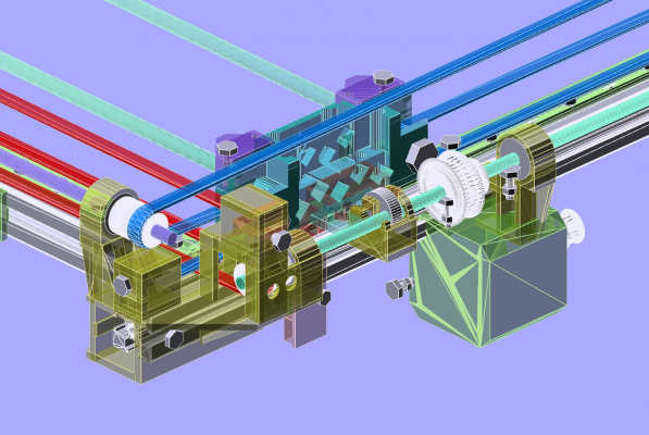
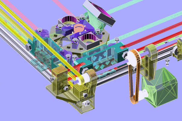
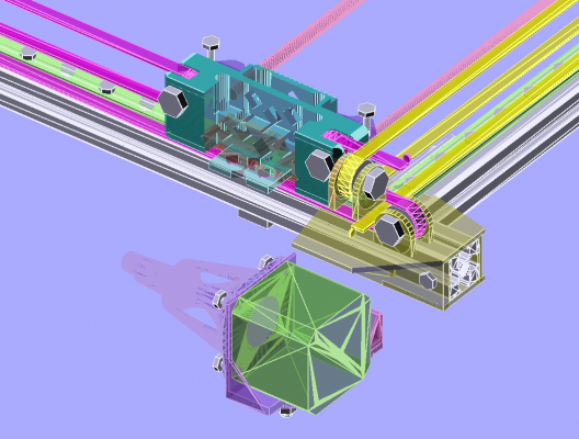
ok so rapid progress, parts (5mm OD 360mm rods, GT2-6mm-40T, 200mm closed loop belts) should be arriving next week, here's a screendump of each of the four corners.
first corner contains rod-end holders for the GT2-6mm-20T so have bearings embedded (hidden behind white GT2-6mm-20T's). access ports (circular) added to get access to the left-hand GT2's grub screws (just in case). belts are held in place with "gnashers" that are on M3 20mm screws, so every belt section can be adjusted by up to around... 5mm. TODO, the NEMA17 holder (NEMA17 is the wrong orientation in this picture).
second corner, this one has a render of the 200mm closed loop belt on the GT2-6mm-40T to the NEMA17 (which has been properly positioned). there is also a bearing holder within 40mm of the GT2-6mm-40T so that the tension from the closed loop belt doesn't bend the 360mm long 5mm rod. this corner holds the other end of one of the rods (yellow bolt) with associated GT2-6mm-20T, but the other axis just has a 625 bearing (red belt) around which the belt is wrapped.
third corner, is still TODO. this one has idler 625 bearings (only) and you can still see the belt-ends hanging in mid-air where there will be adjustable gnashers. underneath is the static extruder NEMA17 with an older G2 Flex3Drive driveshaft housing.
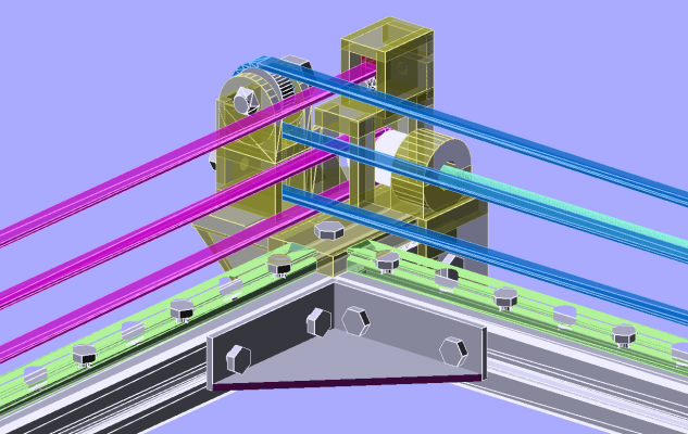
fourth corner, just taken from a different angle just to be diffferent. yes that's really a 50mm steel corner bracket (normally used in wood-working!), it's surprisingly effective. this corner is a near-mirror-image of the second, so has a mix of GT2-6mm-20T (plus 625 bearing) holder for the 5mm rod (purple belt) and a straight 625 bearing idler around which the (blue) belt is wrapped.
i'm pretty happy with these, i should be able to begin verifying the STLs, do a final check stand-alone, and begin 3D printing the first of these corner pieces tomorrow. i already have all four x/y-ends and the mid-point rod-holders done. i do however have to redo the carriage, and also want to refine the space-age alien fan cowling for the hot-end cooling: it could do with expanding somewhat to increase airflow a bit.
lots to do...

|
Re: Riki200 August 21, 2017 10:28PM |
Registered: 6 years ago Posts: 14 |
Quote
o_lampe
Hmmm, I still don't get the argument for the Benson belt gear reduction?
You want to use it to reduce belt tension, but at the same time the belt is longer. Where do you see an advantage? Belt stretch would be the same, right?
I was wondering that myself lately. So I'll try to formulate the problem in mathematical terms, assuming the belt obeys Hooke's law for springs. Also assuming that the belts' length for the pulley case is twice the one for the no-pulley case and that mass and friction of the additional pulleys and belt lengths can be ignored.
m  ... gantry mass (equal for both cases)
a  ... gantry acceleration (equal for both cases)
k  ... rate, spring constant or force constant of the belt
Fg = m * a ... force on the gantry due to acceleration (equal for both cases)
Fb ... force on the belt end (i.e. at the motor)
Xb ... belt stretch due to Fb
Xg ... gantry positioning error due to Xb
So far so good. Now for the equations - please check them yourself, my brain hasn't had coffee today

# No-pulley case
Fb = Fg
Xb = -Fb / k = -Fg / k
Xg = -Fg / k

# Pulley case:
Fb = Fg / 2        ... force on the belt is halved due to pulley
Xb = -2 * Fb / k   ... twice the belt length -> 2 springs in series with the same force
Xg = Xb / 2        ... the gantry moves only half the belt's amount
Xg = -2 * Fb / (2 * k) = -Fb / k   ... substituted Xb from above
Xg = -Fg / (2 * k) ... substituted Fb from the top
This suggests the Xg (gantry positioning error due to belt stretch) is halved for the pulley case compared to the no-pulley case for the same gantry acceleration. Where have I gone wrong?
Edited 3 time(s). Last edit at 08/22/2017 08:12PM by chrigel.
|
Re: Riki200 August 22, 2017 03:57AM |
Registered: 8 years ago Posts: 776 |
Quote
chrigel
This suggests the Xg (gantry positioning error due to belt stretch) is halved for the pulley case compared to the no-pulley case for the same gantry acceleration. Where have I gone wrong?
yippeee! you haven't... and that's the point. that's the bit where we want to find out if it's really true, and then further see if that actually reduces "ringing". that's the real test.
right now i'm running with acceleration figures of 3500mm/sec^2 and even at 80mm/sec it produces definite noticeable bulges at corners and subsequent wall-ripple. i don't care because i get fast functional prints.
but when converting over to the pulley system i *should* be able to *halve* that acceleration number, and have the doubled-up belts take the stretch/strain.
that's assuming of course that any problems *are* isolated to the belt, rather than being tolerances in the plastic of the carriage causing the extruder nozzle to ring / wobble about, etc. etc.
l.
|
Re: Riki200 August 23, 2017 04:03PM |
Registered: 8 years ago Posts: 776 |
ok so i'm pretty much done with the design work, here's some 3D CAD screenshots... y'know... the bright primary colours *really* help distinguish different parts from each other...
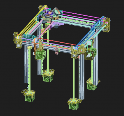
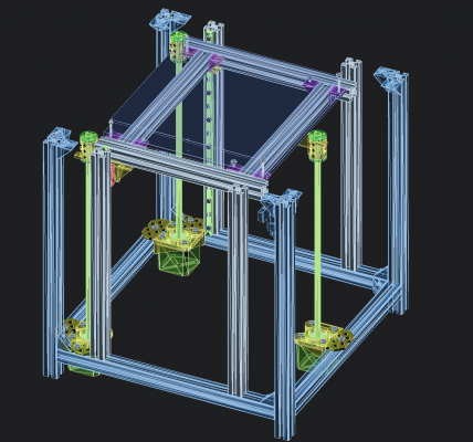
this one's just to show the overall look. the cross-bracing hasn't been rendered, but it's there to rigidise the entire frame. currently i am investigating... don't laugh... coat hanger wire! it's really very strong, 2.5mm steel, bit of a pain to bend into shape. the important thing will be putting something in between each piece of steel to push them apart, create the tension that stiffens up the entire frame.
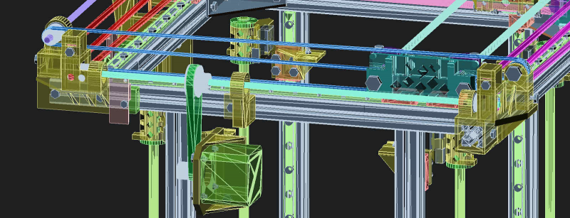
mainly this one is to show how the x and y motors go on. they're attached to the z-uprights (adjustable distance to get the right closed-loop tension), and it will be possible to simply detach the NEMA17, turn it through 180 degrees and reattach it, swapping over to the other pulley to change the ratio from 2.1 to 1:1. replacing the GT2-20T with a GT2-16T on the NEMA17 would get you 2.5:1 or 1.25:1 so it's really very flexible.
anyway i have all the parts printed out, now, i'm just waiting for the 360mm 5mm OD rods, 200mm closed loop belt and the GT2-40T gears, and i can do assembly and testing. the back-to-back belts.... damn. they're starting to wear out very very fast, and i'm keeping them in service by putting coconut oil in between them...
|
Re: Riki200 August 24, 2017 04:51AM |
Registered: 8 years ago Posts: 776 |
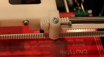
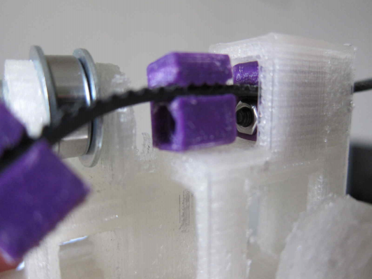
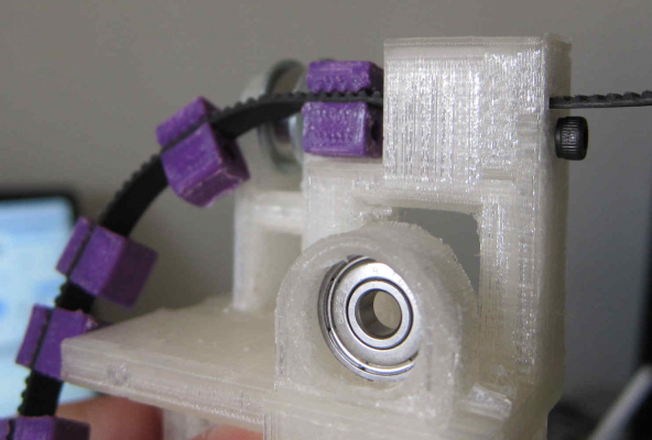
ok these are the belt clamps, quite a simple arrangement: a cube with a 1.5mm cutout and octagons 0.78mm wide for teeth, then an M3 bolt hole and a hex-nut indentation in it. the idea is to slot the belt into it, then use the roof of its holder to make sure that tension on the belt doesn't prise the cube apart. the cut for a belt slot goes nearly all the way through, leaving only about 0.8mm of plastic separating top half and bottom half.
doing this sort of thing was inspired by nophead's mendel90 belt tensioner, which is a *pushing* mechanism and also it's a curve (D-shape) on the mendel90. this is a *pulling* mechanism: the bolt goes *through* the block and pulls it with the nut from the other side. the mendel90 pushes the D-shape away, with the belt wrapped around it, so is a pain because you have to get the allen key in just where there's a tight belt stopping you from turning it more than 270 degrees at a time:
with the "pulling" trick you can see that the belt tensioning can be done from the *end*, where the slack (end) part of the belt doesn't get in the way.
i have *eight* of these (!) because there are 4 belts. luckily it's possible to slacken off th GT2-6mm-20T gears on the 360mm 5mmOD rods instead of having to alter the tension, in order to get belt-pair alignment!
Edited 1 time(s). Last edit at 08/24/2017 04:59AM by lkcl.
|
Masking tape as a flexible air-duct September 01, 2017 08:19AM |
Registered: 8 years ago Posts: 776 |
|
Re: Riki200 September 01, 2017 02:12PM |
Registered: 8 years ago Posts: 776 |
ok so chrigel, i'm updating the Makefile as you find things, so that you can be (yay!) literally the first other person to grab the source code and get up and running with this... completely unique 3D CAD development technique. which would be nice. as it's kinda weird being the only person in the world who uses it.
so the latest mistake i spotted, was, in the git clone .git/config i had the wrong URL. i've been pushing to the *old* printer's repo (the sandwich200) not the new one i put in the new html page, all this time. doh! so the next thing to check will be, can you actually now clone it? there's normally some sort of command that has to be run to make (static) HTML repos clonable... apparently this is "simple"... [nicolasgallagher.com]
so i should just try my own instructions, really, shouldn't i ok so doing the git clone [hands.com] and wow that's a big damn repo for a 3D printer, what did i do hmmm... i'll find out soon enough if i did something silly like add an STL file to it...
it's taking a while so i'll do the "make download" shortly.
so the latest mistake i spotted, was, in the git clone .git/config i had the wrong URL. i've been pushing to the *old* printer's repo (the sandwich200) not the new one i put in the new html page, all this time. doh! so the next thing to check will be, can you actually now clone it? there's normally some sort of command that has to be run to make (static) HTML repos clonable... apparently this is "simple"... [nicolasgallagher.com]
so i should just try my own instructions, really, shouldn't i
 ok so doing the git clone [hands.com] and wow that's a big damn repo for a 3D printer, what did i do hmmm... i'll find out soon enough if i did something silly like add an STL file to it...
it's taking a while so i'll do the "make download" shortly.
|
Re: Riki200 September 02, 2017 08:18AM |
Registered: 6 years ago Posts: 14 |
Awesome lkcl, thanks for getting the git link working. Cloning it was a breeze.
Then the dreaded "make download" failed again of course, on the URL http://mutley3d.com/DLoads/FlexSTL.rar as mutley3d.com doesn't exist any more and there are no downloads at the new flex3drive.com page.
I asked Jason from Flex3Drive for the G2 extruder STL files but he emailed me G3 STLs instead (maybe because G2 isn't sold any more?).
So I thought, maybe you could just upload the extruder STL files to some site (e.g. hands.com) where your Makefile could find them, but Jason mentioned in an email that Flex3Drive will themselves make the STL files available shortly after figuring out the licensing And in the meanwhile he asked me not to distribute the files elsewhere ...Sooo until that issue is resolved, I don't think anyone can re-create your work, at least without contacting Flex3Drive themselves and asking for the STLs.
Now of course, I tried to "make" the Riki200 anyway and interestingly, the build failed *not* because of the missing STLs but instead at a missing "foursplit_spline" import... maybe a file you haven't added to the repo yet?
One more question, on the G2 vs. G3 extruders: Which one will you be using for the Riki200?
Then the dreaded "make download" failed again of course, on the URL http://mutley3d.com/DLoads/FlexSTL.rar as mutley3d.com doesn't exist any more and there are no downloads at the new flex3drive.com page.
I asked Jason from Flex3Drive for the G2 extruder STL files but he emailed me G3 STLs instead (maybe because G2 isn't sold any more?).
So I thought, maybe you could just upload the extruder STL files to some site (e.g. hands.com) where your Makefile could find them, but Jason mentioned in an email that Flex3Drive will themselves make the STL files available shortly after figuring out the licensing And in the meanwhile he asked me not to distribute the files elsewhere
 ...Sooo until that issue is resolved, I don't think anyone can re-create your work, at least without contacting Flex3Drive themselves and asking for the STLs.
Now of course, I tried to "make" the Riki200 anyway and interestingly, the build failed *not* because of the missing STLs but instead at a missing "foursplit_spline" import... maybe a file you haven't added to the repo yet?
One more question, on the G2 vs. G3 extruders: Which one will you be using for the Riki200?
|
Re: Riki200 September 02, 2017 10:13AM |
Registered: 8 years ago Posts: 776 |
Quote
chrigel
Awesome lkcl, thanks for getting the git link working. Cloning it was a breeze.
great.
Quote
Then the dreaded "make download" failed again of course, on the URL http://mutley3d.com/DLoads/FlexSTL.rar as mutley3d.com doesn't exist any more and there are no downloads at the new flex3drive.com page.
I asked Jason from Flex3Drive for the G2 extruder STL files but he emailed me G3 STLs instead (maybe because G2 isn't sold any more?).
ok drop that in place instead, it doesn't matter. the critical bit is this, in v3/flex3drive.py:
class Flex3DriveG2Base(STLObject):
    def __init__(self):
        STLObject.__init__(self,
                    "flexstl/g2/ExtruderBase.stl",
                                 BOM_3D,
                    )
make sure that there's at least... _some_ file there, even if it's blank, and if it's not the same just put in "self.visible(False)" to make it disappear temporarily ok?
Quote
So I thought, maybe you could just upload the extruder STL files to some site (e.g. hands.com) where your Makefile could find them, but Jason mentioned in an email that Flex3Drive will themselves make the STL files available shortly after figuring out the licensing And in the meanwhile he asked me not to distribute the files elsewhere...Sooo until that issue is resolved, I don't think anyone can re-create your work, at least without contacting Flex3Drive themselves and asking for the STLs.
they can - just do as above, temporarily.
Quote
Now of course, I tried to "make" the Riki200 anyway and interestingly, the build failed *not* because of the missing STLs but instead at a missing "foursplit_spline" import... maybe a file you haven't added to the repo yet?
ah that means i've been editing the files and not run "make upload" in the 3dcase directory (where make download gets these files from).
no i will NOT be adding copies of library files to a git repo. you do not do that: it is extremely bad practice. instead, dependencies are managed in the way i've done them... i just haven't kept them up-to-date because you're literally the only other person in the world using this.
so, anyway, i've just updated again, so do that "make download" again, ignoring (again) the unrar error
Quote
One more question, on the G2 vs. G3 extruders: Which one will you be using for the Riki200?
neither. a direct drive extruder with a direct-drive adapter: [flex3drive.com]
my *personal* one uses a G2 because that's what i have available. however i have a direct-drive adapter on order and will be making a direct-drive extruder to fit it. i will also be replacing the Flex3DriveG2ClampE3D part. probably. see class Flex3DriveG2Base in v3/flex3drive.py
btw i've just added a .vimrc file (so do a git pull), you can hit "+" in vi to get it to run "python riki200_model.py" automatically. very useful for automatic updating of the model. edit, hit "+", openscad automatically refreshes. another edit, "+".
the macro also includes "saving the current file" before running the command. so watch out for that.
l.
|
Re: Riki200 September 02, 2017 07:07PM |
Registered: 8 years ago Posts: 776 |
ok so basic instructions, edit riki_model.py and look for show_zassembly = True and so on. this is such a CPU-intensive model that i had to make ways to cut certain portions. that's done with those booleans. even so, on a quad-core i7 3.5ghz machine, openscad only manages an opengl frame rate of one SECOND per frame on the main xy assembly.
that's also unacceptable and also stuff gets in the way so there's another way to render: an example is in flex3drive.py. this trick only works in the main directory due to the way python imports work:
that's basically exactly the same as what's in riki_model.py.
so after loading those vimrc macros you can:
the "+" macro does something similar but always executes riki_model.py instead of the current file.
anyway on the checkedout version i just confirmed it works.
if you want to generate the STL files, which takes a looong time, look towards the end of riki_model.py, for printer.generate_stls() and uncomment it but also change the booleans to True for everything. the BOM is also auotgenerated, and if you used "make" it's turned into a PDF. you'l need enscript and ps2pdf for that to work though.
that's also unacceptable and also stuff gets in the way so there's another way to render: an example is in flex3drive.py. this trick only works in the main directory due to the way python imports work:
if __name__ == '__main__':
        #c = Flex3DriveCarriagePlotCoolingFanHolder()
        c = Flex3DriveG2Base()
        u = c.obj()
        scad_render_to_file(u, "riki200_model.scad")
        #c.generate_stls()
that's basically exactly the same as what's in riki_model.py.
so after loading those vimrc macros you can:
- vi flex3drive.py
- make some edits
- hit the "comma" key which does a save and executes the CURRENT file.
the "+" macro does something similar but always executes riki_model.py instead of the current file.
anyway on the checkedout version i just confirmed it works.
if you want to generate the STL files, which takes a looong time, look towards the end of riki_model.py, for printer.generate_stls() and uncomment it but also change the booleans to True for everything. the BOM is also auotgenerated, and if you used "make" it's turned into a PDF. you'l need enscript and ps2pdf for that to work though.
|
Re: Riki200 September 05, 2017 10:45PM |
Registered: 6 years ago Posts: 14 |
Thanks for the updates.
On the topic of missing STLs:
Whatever you did in the last commits, after the update and "make download", everything seems to be working - I haven't had the need for empty (or different) STL files so far, which is good.
Sorry, I wasn't aware that "foursplit_spline.py" was a library. Anyway, it's not a problem any more.
Regarding the G2 vs. G3 extruders:
Interesting. I didn't realise until now that the G3 (not sure whether this applies to the G2 as well) probably isn't really suitable as it has the hot end fan hanging off the bottom - which looks to my untrained eye as it'd likely be interfering with your carriage. Now I also understand why you created that fancy fan duct ...
...
...anyway, that'll mean the G3 STL files I have aren't good either as they don't even include the Direct Drive Adapter models as far as I have seen. Since it looks rather like a very "short" NEMA motor with a driveshaft mount at its top, I guess it shouldn't be too hard to model
Thanks, found it. For anyone wanting to look at the whole thing (except the side panels), this is what I used:
 ... looks like a leftover from the Sandwich200. Also note that initially (or after resetting the view in OpenSCAD), the whole thing is upside-down, i.e. the z-axis is inverted or, in other words, higher values for z mean further down the Riki200 model.
Also I was able to generate the STLs and BOM PDF, yay!
And yes, it is definitely slow to look at... ...but what can you do, it just is quite a complex model! One thing I (as a complete noob) do miss about OpenSCAD is the ability to click on an element in the 3D view, highlight or hide it, tell me what it is and ideally where I can find it in the source... but that's probably better addressed to the OpenSCAD community.
Edited 1 time(s). Last edit at 09/05/2017 10:51PM by chrigel.
On the topic of missing STLs:
Quote
lkcl
make sure that there's at least... _some_ file there, even if it's blank, and if it's not the same just put in "self.visible(False)" to make it disappear temporarily ok?
Whatever you did in the last commits, after the update and "make download", everything seems to be working - I haven't had the need for empty (or different) STL files so far, which is good.
Quote
lkcl
no i will NOT be adding copies of library files to a git repo. you do not do that: it is extremely bad practice.
Sorry, I wasn't aware that "foursplit_spline.py" was a library. Anyway, it's not a problem any more.
Regarding the G2 vs. G3 extruders:
Quote
lkcl
my *personal* one uses a G2 because that's what i have available. however i have a direct-drive adapter on order and will be making a direct-drive extruder to fit it. i will also be replacing the Flex3DriveG2ClampE3D part. probably. see class Flex3DriveG2Base in v3/flex3drive.py
Interesting. I didn't realise until now that the G3 (not sure whether this applies to the G2 as well) probably isn't really suitable as it has the hot end fan hanging off the bottom - which looks to my untrained eye as it'd likely be interfering with your carriage. Now I also understand why you created that fancy fan duct
 ...
......anyway, that'll mean the G3 STL files I have aren't good either as they don't even include the Direct Drive Adapter models as far as I have seen. Since it looks rather like a very "short" NEMA motor with a driveshaft mount at its top, I guess it shouldn't be too hard to model

Quote
lkcl
ok so basic instructions, edit riki_model.py and look for show_zassembly = True and so on. this is such a CPU-intensive model that i had to make ways to cut certain portions. that's done with those booleans.
Thanks, found it. For anyone wanting to look at the whole thing (except the side panels), this is what I used:
    stow = False
    show_belts = True
    show_box = True
    show_zassembly = True
    show_plotxy = True
    show_bed = True
    show_panels = False
...the first "stow" line had me confused for a second, as it was set to True  ... looks like a leftover from the Sandwich200. Also note that initially (or after resetting the view in OpenSCAD), the whole thing is upside-down, i.e. the z-axis is inverted or, in other words, higher values for z mean further down the Riki200 model.
Also I was able to generate the STLs and BOM PDF, yay!
And yes, it is definitely slow to look at...
 ...but what can you do, it just is quite a complex model! One thing I (as a complete noob) do miss about OpenSCAD is the ability to click on an element in the 3D view, highlight or hide it, tell me what it is and ideally where I can find it in the source... but that's probably better addressed to the OpenSCAD community.
Edited 1 time(s). Last edit at 09/05/2017 10:51PM by chrigel.
|
Re: Riki200 September 05, 2017 11:03PM |
Registered: 8 years ago Posts: 776 |
Quote
chrigel
Thanks for the updates.
On the topic of missing STLs:
Quote
lkcl
make sure that there's at least... _some_ file there, even if it's blank, and if it's not the same just put in "self.visible(False)" to make it disappear temporarily ok?
Whatever you did in the last commits, after the update and "make download", everything seems to be working - I haven't had the need for empty (or different) STL files so far, which is good.
awesome.
Quote
Quote
lkcl
no i will NOT be adding copies of library files to a git repo. you do not do that: it is extremely bad practice.
Sorry, I wasn't aware that "foursplit_spline.py" was a library. Anyway, it's not a problem any more.
yehyeh sorry. good.
Quote
Regarding the G2 vs. G3 extruders:
Quote
lkcl
my *personal* one uses a G2 because that's what i have available. however i have a direct-drive adapter on order and will be making a direct-drive extruder to fit it. i will also be replacing the Flex3DriveG2ClampE3D part. probably. see class Flex3DriveG2Base in v3/flex3drive.py
Interesting. I didn't realise until now that the G3 (not sure whether this applies to the G2 as well) probably isn't really suitable as it has the hot end fan hanging off the bottom - which looks to my untrained eye as it'd likely be interfering with your carriage. Now I also understand why you created that fancy fan duct...
yay! someone else understands what i've been doing and why! achievement!

Quote
...anyway, that'll mean the G3 STL files I have aren't good either as they don't even include the Direct Drive Adapter models as far as I have seen. Since it looks rather like a very "short" NEMA motor with a driveshaft mount at its top, I guess it shouldn't be too hard to model
there's a NEMA-17 already in the model *grumble* i seem to have added the STL file *grumble* that'll have to go... no the G3 is a totally different product and design from the direct-drive adapter so it's a bit unfair to say "the archive doesn't even include it".
no i will need to develop a direct-drive extruder which will sit on that carriage, then you would simply (optionally) drop in the Direct-Drive adapter and get some weight-reduction.
Quote
Quote
lkcl
ok so basic instructions, edit riki_model.py and look for show_zassembly = True and so on. this is such a CPU-intensive model that i had to make ways to cut certain portions. that's done with those booleans.
Thanks, found it. For anyone wanting to look at the whole thing (except the side panels), this is what I used:
    stow = False
    show_belts = True
    show_box = True
    show_zassembly = True
    show_plotxy = True
    show_bed = True
    show_panels = False
...the first "stow" line had me confused for a second, as it was set to True... looks like a leftover from the Sandwich200.
yehyeh, there's quite a lot i haven't yet removed.
Quote
Also note that initially (or after resetting the view in OpenSCAD), the whole thing is upside-down, i.e. the z-axis is inverted or, in other words, higher values for z mean further down the Riki200 model.
yeah there's some offsetting i did and haven't got round to moving it back to origin, it was something to do with the function-based moving around of parts for when the "stow" option was or was not set...
Quote
Also I was able to generate the STLs and BOM PDF, yay!
briiilliant.
Quote
And yes, it is definitely slow to look at......but what can you do, it just is quite a complex model!
yehyeh. that's why all those options are there - to cut out bits. don't generate STL files unless you absolutely need to. and also do the trick of using "self.set_visible(False)" or call that same function on any object instance. then also you can create and instantiate your own objects, with your own python file (cut/paste how it's done in flex3drive.py), just remember to respect python import rules i.e. don't try the trick in a subdirectory e.g. v3 and expect "import fred" where fred.py is in the *parent* directory. create the file *in* the parent directory then use "from v3.foo import bar" instead.
Quote
One thing I (as a complete noob) do miss about OpenSCAD is the ability to click on an element in the 3D view, highlight or hide it, tell me what it is and ideally where I can find it in the source... but that's probably better addressed to the OpenSCAD community.
yyyeahhh they'd need to have sub-assemblies marked by name, first, in order to do that, either as an argument to things like union() or even cube() etc. this is partly why i make significant use of colour.
bottom line, you can follow the source code, play with the booleans, add some more if you want to, insert "self.set_visible(False)" at various points and generally mess about.
damn you're right, a name would be extremely useful. you want to raise that as a feature-request?
l.
|
Re: Riki200 September 06, 2017 03:59AM |
Registered: 6 years ago Posts: 14 |
Quote
lkcl
Quote
chrigel
...anyway, that'll mean the G3 STL files I have aren't good either as they don't even include the Direct Drive Adapter models as far as I have seen. Since it looks rather like a very "short" NEMA motor with a driveshaft mount at its top, I guess it shouldn't be too hard to model
there's a NEMA-17 already in the model *grumble* i seem to have added the STL file *grumble* that'll have to go... no the G3 is a totally different product and design from the direct-drive adapter so it's a bit unfair to say "the archive doesn't even include it".
Sorry, again I wasn't clear enough: What I meant was the STL package Jason from Flex3Drive emailed me in response to my request for the G2 extruder STLs. So he sent the G3 STL package (the "archive" I was referring to because it was a RAR file), in which I couldn't find anything that looks like the Direct Drive Adapter they have on their web page. But since that adapter looks like a shortened NEMA-17 motor (or *should* look like one, as it is arguably designed to replace the same), hopefully modelling it won't be too hard if it can be based on the existing NEMA-17 model that you already have there. Ah yes, just saw that it's part of the git repo.
I can try and create a patch to remove it from there and add it to the "make download" target instead if that's what you want... bear with me though, while I know Mercurial somewhat, git is still quite new to me... but I guess it's never too late to learn!
Quote
lkcl
... i will need to develop a direct-drive extruder which will sit on that carriage, then you would simply (optionally) drop in the Direct-Drive adapter and get some weight-reduction.
Now I am a bit confused - do you mean that the standard Riki200 will have a NEMA-17 sitting on the carriage instead of the Direct-Drive adapter? To save those 65GBP?
Or maybe I am wrong in my understanding of the available options here, which I *think* are:
1. NEMA-17 axis connected directly to your custom-developed direct-drive extruder, both on the carriage.
2. NEMA-17 mounted on the frame, its axis driving a flexible drive shaft which powers the Flex3Drive Direct-Drive adapter (40:1 worm gear) which is then connected to your custom-developed direct-drive extruder.
3. Same as 2, but using a ready-made, complete extruder (including the 40:1 gear) from Flex3Drive (such as the G3) instead of the Direct-Drive-plus-custom-extruder... but we've ruled that out already because of the fan (see above).
Currently, I am thinking option 2 would be preferable because of the weight, just as you said.
Edited 1 time(s). Last edit at 09/06/2017 04:00AM by chrigel.
|
Re: Riki200 September 07, 2017 07:07PM |
Registered: 8 years ago Posts: 776 |
Quote
chrigel
Sorry, again I wasn't clear enough: What I meant was the STL package Jason from Flex3Drive emailed me in response to my request for the G2 extruder STLs. So he sent the G3 STL package (the "archive" I was referring to because it was a RAR file),
yehyeh. because it's a totally different product, totally different design. if you'd asked about e.g. the kossel-mini flex3drive he would have sent you that set of design files instead... and you still would not have received anything which contained the *completely* separate product's design files for the Direct Drive Adapter product.
Quote
in which I couldn't find anything that looks like the Direct Drive Adapter they have on their web page. But since that adapter looks like a shortened NEMA-17 motor (or *should* look like one, as it is arguably designed to replace the same), hopefully modelling it won't be too hard if it can be based on the existing NEMA-17 model that you already have there. Ah yes, just saw that it's part of the git repo.
well.. the simplest thing to do would be to either find someone else's "short" NEMA17 STL file.... or just... cheat: use the "resize" function!
Quote
I can try and create a patch to remove it from there and add it to the "make download" target instead if that's what you want...
Quote
bear with me though, while I know Mercurial somewhat, git is still quite new to me... but I guess it's never too late to learn!
you should easily be able to find a tuturial by searching "git for mercurial users". that should give you a chart of equivalent commands. one you'll need though is "git-format-patch" in combination with "git log" to find the revision number of the commit(s). you can then email me the files it creates.
Quote
Quote
lkcl
... i will need to develop a direct-drive extruder which will sit on that carriage, then you would simply (optionally) drop in the Direct-Drive adapter and get some weight-reduction.
Now I am a bit confused - do you mean that the standard Riki200 will have a NEMA-17 sitting on the carriage instead of the Direct-Drive adapter? To save those 65GBP?
it *can* have a NEMA17 sitting on the carriage. people *can* save 65 GBP if they so choose.
Quote
Or maybe I am wrong in my understanding of the available options here, which I *think* are:
1. NEMA-17 axis connected directly to your custom-developed direct-drive extruder, both on the carriage.
2. NEMA-17 mounted on the frame, its axis driving a flexible drive shaft which powers the Flex3Drive Direct-Drive adapter (40:1 worm gear) which is then connected to your custom-developed direct-drive extruder.
3. Same as 2, but using a ready-made, complete extruder (including the 40:1 gear) from Flex3Drive (such as the G3) instead of the Direct-Drive-plus-custom-extruder... but we've ruled that out already because of the fan (see above).
Currently, I am thinking option 2 would be preferable because of the weight, just as you said.
both 1 *and* 2. then later option (4) - custom-make an extruder which uses the PARTS of a flex3drive product (pick one).
|
Re: Riki200 September 07, 2017 11:50PM |
Registered: 8 years ago Posts: 776 |
ok so i went to visit my friend in HK who will be making a riki200 (latest version) and he'd tracked down the parts needed to modify the v2: 360mm long 5mm OD rods for driveshafts, GT2-6mm-40T and some GT2-6mm-200mm long closed loop belts.
i'm also going to take the disassembly opportunity to convert over to a triple leadscrew z-arrangement where previously it was 4. the first question was, "is 4 really needed" and the answer's no not really, the second was "will it be cheaper to do" and the answer's "yes".
i originally wanted 4 because when it comes to auto-z-levelling 4 would be easier on the software. each lead screw was therefore placed symmetrically exactly in the corners of a perfect square, with the printbed's centre being exactly the same point as the square formed by the 4 leadscrews. i overruled this after thinking that software can always be written

|
Re: Riki200 September 08, 2017 05:30AM |
Registered: 8 years ago Posts: 776 |
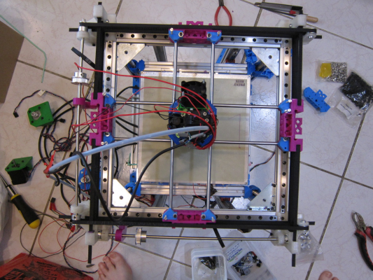
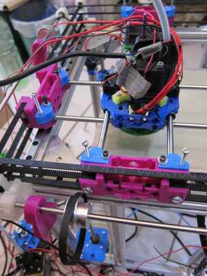
okaay so this is what the top looks like, now. not too much in the way of mistakes - nothing that will completely stop the printer from running in order to print replacement parts. the 360mm long 5mm OD rods however are bending an awwwful lot - far more than i'm happy with, so i will need double 625 bearings, one either side of the GT2-6mm-20T. it's the pressure on the GT2-6mm-20T from the belts that's causing the rod to bend.
a couple places where belts rub... motor support needs a cutaway... generally nothing major
a couple places where belts rub... motor support needs a cutaway... generally nothing major
|
Riki200 v3 FIrst print! September 09, 2017 09:46PM |
Registered: 8 years ago Posts: 776 |
Success!
[youtu.be]
ok i say "success" but it's running so fast that it's outside the rated speed of a NEMA17 motor. i will be flipping over to 1:1 on the closed loop belt now and trying that out.
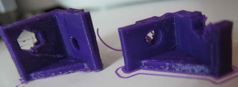
one on the LEFT was done at a sane speed: this completed fine. min jerk speeds were set quite low. one on the RIGHT was set at insane speeds (180mm/sec), acceleration (4000 mm / sec ^2) and min-jerk (1000 mm / min or 16 mm / sec). apart from the fact that the 180mm/sec times two for the pulleys times two for the closed loop was outside of the rated speed of a NEMA17 the quality came out BETTER than the slower speed one: less corner-bulging by a long long way.
i think this is down to just letting the printer sort itself out instead of trying to slow down in corners. this can only really be done with this printer because the carriage is lighter (no NEMA17 mounted on it) and the belts are doubled-up so take half the strain each. consequently the kinds of "ringing" you'd normally expect to see simply... isn't there.
close inspection of both printed parts shows that there is actually a small amount of "ringing" but bizarrely the first part (slower) is worse!
|
Re: Riki200 v3 FIrst print! September 10, 2017 02:22AM |
Registered: 8 years ago Posts: 5,232 |
|
Re: Riki200 v3 FIrst print! September 10, 2017 02:49AM |
Registered: 8 years ago Posts: 776 |
Quote
o_lampe
You already run it with 24V?
I'm sure there is a golden spot in gear ratio. Maybe try 30:20 tooth ratio?
yehyeh 24v. i have some GT2-16T around somewhere so could get close to that. it's a bit of a pain to disassemble though, requires undoing and re-tensioning all 8 belt tensioners.
|
Re: Riki200 v3 FIrst print! September 10, 2017 05:59AM |
Registered: 8 years ago Posts: 5,232 |
|
Re: Riki200 v3 FIrst print! September 10, 2017 06:16AM |
Registered: 8 years ago Posts: 776 |
Quote
o_lampe
You mentioned the belt tension would bend the rod.
is bending, yes.
Quote
Maybe it's the right time to split the 5mm rod and use dual bearings and flexible couplings?
This way you could make it more maintenance friendly and stiffer the same time.
huh. it sounds like a good idea... except... *thinks*... i like the easier maintanence bit... except... those 5mm OD rods were incredibly cheap, from a market in HK. literally sawn off while-you-wait and came with free burrs to cut your fingers on.
adding couplings adds cost, but also doesn't solve the problem that, really, the rods shouldn't be bending in the first place. basically it means that i haven't put dual bearings in, and/or that i didn't put the belt close enough to the bearing(s). you can see from the pictures and video, i put the GT2-6mm-20T the opposite way round so that the bit you tighten up givesa good 10mm separation between belt and bearing: i should have made that the other way round and then it wouldn't matter so much.
the only thing is, 2 bearings is going to be *really* awkward to get the GT2-6mm-20T in between, regardless of what coupling is used. hmm....
Sorry, only registered users may post in this forum.
