Leadscrew driven XY gantry printer?
Posted by klcjr89
|
Leadscrew driven XY gantry printer? March 21, 2018 09:23PM |
Registered: 6 years ago Posts: 207 |
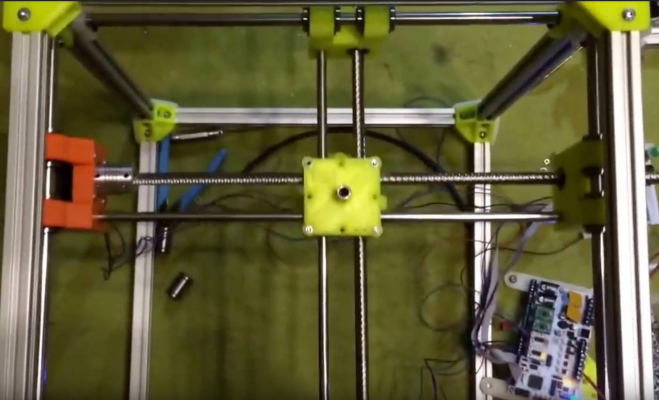
I have been thinking about which way I want to go in designing my next printer. I found this video on YouTube: [youtu.be] Picture if you can't watch the video:
Which shows a leadscrew driven crossed bar XY gantry.
I think I want to implement this design, except without moving the mass of the motors like in the video above shows.
I had an all leadscrew driven axes i3 style printer and it worked very well. It printed and traveled very fast even with TR8x8 leadscrews which is attributed to the 120kHz step frequency I had set in Smoothieware, low inertia motors, and 24V power.
I sold this printer and am wanting to build something from scratch this time.
Using the leadscrews got rid of ringing and ghosting artifacts (especially on the moving bed with 1/4" Mic-6 bed). There was no backlash with the leadscrews using these adjustable Delrin nut blocks:
I ruled out ballscrews long ago due to their increased size, weight, and harmonics transferred through the ballnut.
Is there anything I should watch out for or any 'gotchas'?
Unlike my other threads on the other designs I've posted, I have decided I want to keep the gantry fixed and at the top of the printer, with the bed moving in Z to keep the amount of moving wires to a minimum.
I will incorporate the_digital_dentist's three point leveling for the bed.
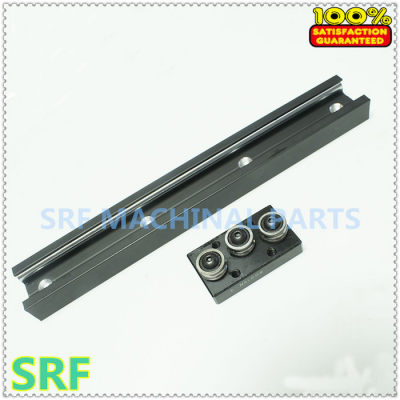
I am evaluating using these linear guides which I've only seen SublimeLayers use on a delta printer: Note, this image is a Chinese clone, in my build I would be using the genuine LM76 (USA) ones.
These use three bearings, two fixed and one on an eccentric. This style of linear guide has been proven on CNC machines and plasma tables.
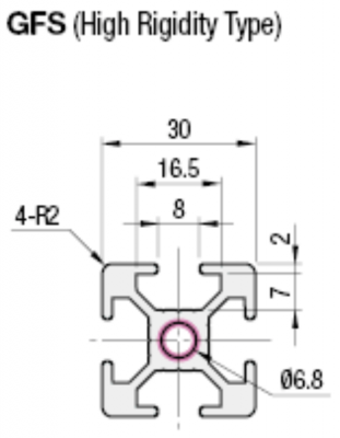
Planned extrusions will be Misumi 30x30mm GFS series (thicker cross section).
Edited 19 time(s). Last edit at 03/22/2018 01:10PM by klcjr89.
|
Re: Leadscrew driven XY gantry printer? March 22, 2018 04:54AM |
Registered: 8 years ago Posts: 5,232 |
|
Re: Leadscrew driven XY gantry printer? March 22, 2018 08:40AM |
Registered: 6 years ago Posts: 90 |
Quote
o_lampe
Quote
I think I want to implement this design, except without moving the mass of the motors like in the video above shows.
Will be interesting to see, how?
My first idea was: bevelled gears and a keyed smooth rod to drive the bevelled gear.
So the "differential" slides along the keyed drive rod? Could be cool. Maybe use a square shaft rather than a keyed round one?
|
Re: Leadscrew driven XY gantry printer? March 22, 2018 11:00AM |
Registered: 6 years ago Posts: 207 |
Quote
o_lampe
Quote
I think I want to implement this design, except without moving the mass of the motors like in the video above shows.
Will be interesting to see, how?
My first idea was: bevelled gears and a keyed smooth rod to drive the bevelled gear.
Pretty easy, just dual leadscrews coupled with a belt for each axis. Think of the ultimaker, but with leadscrews. No keyed shafts or anything should be necessary.
Edited 2 time(s). Last edit at 03/22/2018 11:02AM by klcjr89.
|
Re: Leadscrew driven XY gantry printer? March 22, 2018 12:06PM |
Registered: 8 years ago Posts: 5,232 |
Quote
gtj
Quote
o_lampe
Quote
I think I want to implement this design, except without moving the mass of the motors like in the video above shows.
Will be interesting to see, how?
My first idea was: bevelled gears and a keyed smooth rod to drive the bevelled gear.
So the "differential" slides along the keyed drive rod? Could be cool. Maybe use a square shaft rather than a keyed round one?
Square shaft that runs in standard bearings would be nice.
@klcjr89
I can't picture it, can't wait to see a drawing...

Edited 1 time(s). Last edit at 03/22/2018 12:07PM by o_lampe.
|
Re: Leadscrew driven XY gantry printer? March 22, 2018 03:23PM |
Registered: 6 years ago Posts: 207 |
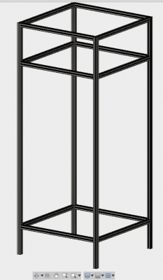
Here is what I'm thinking of for the frame design.
Extrusions are Misumi 30x30 GFS 6 series. Frame dimensions: Approximately 1500mm x 700mm wide (square).
Leveling feet/wheels will be added to the base legs. Uninterruptable power supply will be mounted in the bottom area.
Side enclosure panels will be polycarbonate.
Edited 4 time(s). Last edit at 03/22/2018 03:39PM by klcjr89.
|
Re: Leadscrew driven XY gantry printer? March 24, 2018 11:06PM |
Registered: 7 years ago Posts: 507 |
I recall lkcl planning to build a printer similar in concept. He wanted to use belts, thought but the placement of the driving force was the same (the belts/screws apply force very close to the X intersection). He ended up having an issue with binding when the XY assembly was further off center, it would cause a moment on the perimeter bearings since you're pulling/pushing close to one set of bearings than the other.
|
Re: Leadscrew driven XY gantry printer? March 24, 2018 11:10PM |
Registered: 6 years ago Posts: 207 |
Quote
Trakyan
I recall lkcl planning to build a printer similar in concept. He wanted to use belts, thought but the placement of the driving force was the same (the belts/screws apply force very close to the X intersection). He ended up having an issue with binding when the XY assembly was further off center, it would cause a moment on the perimeter bearings since you're pulling/pushing close to one set of bearings than the other.
My plan was for the leadscrews to drive the 'outer perimeter' of the XY plane. Imagine, four Hiwin guides and two leadscrews synchronized with a belt per axis. There would be two more Hiwin guides to make up the 'crossed bar' printhead mechanism.
Edited 3 time(s). Last edit at 03/24/2018 11:12PM by klcjr89.
|
Re: Leadscrew driven XY gantry printer? March 25, 2018 02:12PM |
Registered: 11 years ago Posts: 5,780 |
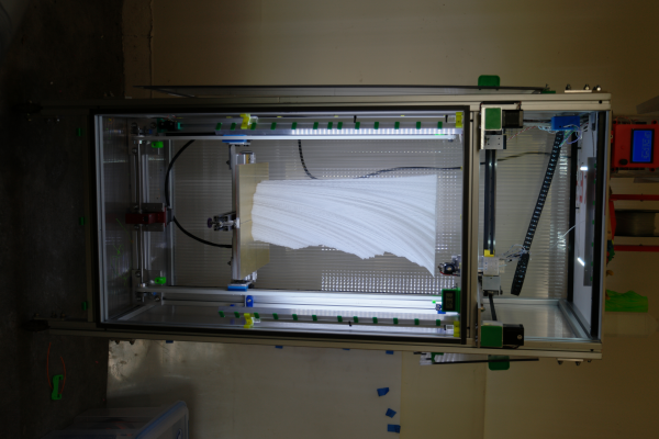
I used 40x40 mm t-slot for a similar sized frame and ended up adding some aluminum plate corner bolsters to the sides of the frame because the moving mass in the Y axis was moving the frame a bit more than I was happy with. The dual layer PC enclosure panels I used don't attach rigidly to the frame (they are just cut to fit inside the slots) so they don't help with frame rigidity. They are very light weight and provide thermal insulation as well as light transmission.
I used skate wheels on the front legs, and leveling feet on the rear, all of which which make it very easy to move the machine around, except for going up and down stairs. I'm watching for a deal on some larger wheels to make that easier.
Ultra MegaMax Dominator 3D printer: [drmrehorst.blogspot.com]
|
Re: Leadscrew driven XY gantry printer? March 25, 2018 04:13PM |
Registered: 6 years ago Posts: 90 |
|
Re: Leadscrew driven XY gantry printer? March 25, 2018 04:47PM |
Registered: 11 years ago Posts: 5,780 |
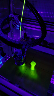
It is laid out in a big circular loop. The frame attached end opens toward the front of the printer and the extruder carriage end opens toward the rear of the printer. That keeps the radius of curvature relatively large which should minimize wire failures due to excessive flexing. It's a little dark but you can see what it's doing in this picture:
Ultra MegaMax Dominator 3D printer: [drmrehorst.blogspot.com]
Ultra MegaMax Dominator 3D printer: [drmrehorst.blogspot.com]
|
Re: Leadscrew driven XY gantry printer? March 25, 2018 05:20PM |
Registered: 6 years ago Posts: 90 |
Quote
the_digital_dentist
It is laid out in a big circular loop. The frame attached end opens toward the front of the printer and the extruder carriage end opens toward the rear of the printer. That keeps the radius of curvature relatively large which should minimize wire failures due to excessive flexing. It's a little dark but you can see what it's doing in this picture:
Gotcha, thanks!
Sorry, only registered users may post in this forum.
