Black Beauty Build Log
Posted by gtj
|
Black Beauty Build Log May 24, 2018 10:52AM |
Registered: 6 years ago Posts: 90 |
Continuation of HyperCube OverKill
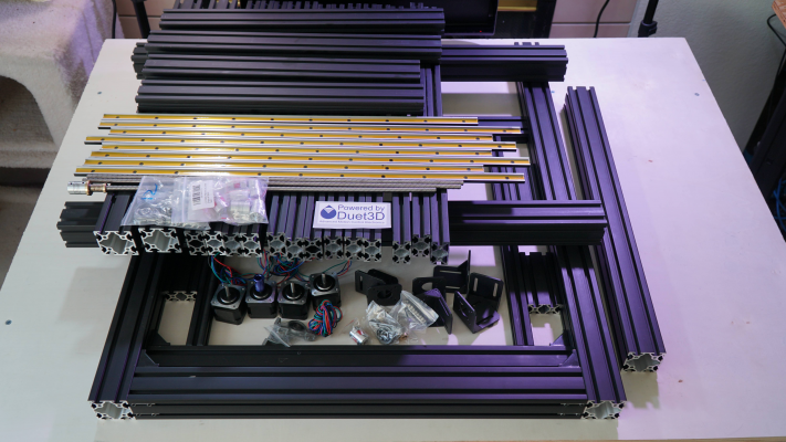
I got a shipment of aluminum extrusions yesterday so it's time to start building for real!
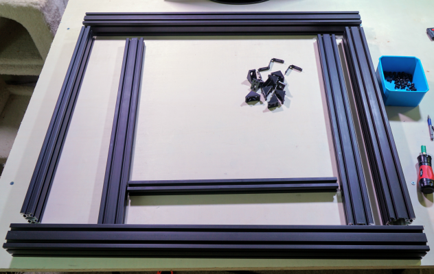
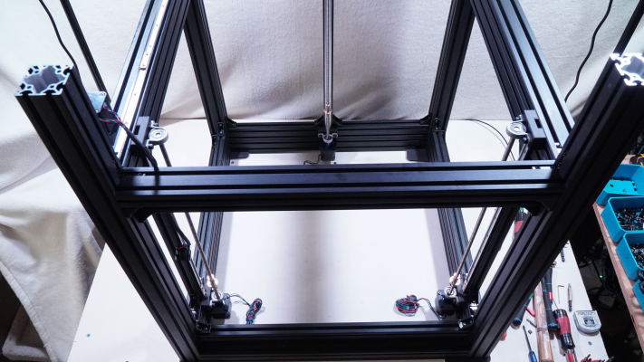
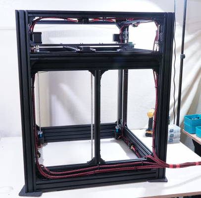
I had to build a bigger work surface for this thing.
The footprint stands at 684x684 and 800mm tall.
The actual build area has been increased to 500x500x500.
I got a shipment of aluminum extrusions yesterday so it's time to start building for real!
I had to build a bigger work surface for this thing.
The footprint stands at 684x684 and 800mm tall.
The actual build area has been increased to 500x500x500.
|
Re: Black Beauty Build Log May 25, 2018 03:13AM |
Registered: 8 years ago Posts: 5,232 |
|
Re: Black Beauty Build Log May 27, 2018 01:20PM |
Registered: 8 years ago Posts: 49 |
|
Re: Black Beauty Build Log May 27, 2018 05:24PM |
Registered: 6 years ago Posts: 90 |
Quote
o_lampe
Nice!
How much did you get for placing the Duet sticker in the picture
Heh, not a penny.
Seriously, I should mention that regardless of what I say about the products I used, I paid full price for all of them. There were no freebies.
Quote
Archiclem
Really like the igus rails! Can't wait to see the final mount! How much does they cost?
The ones in the picture (4 ea 584mm and 4 ea 650mm) were a total of $200. There are actually 4 more that I'm reusing from the prototype.
|
Side Panels May 27, 2018 05:36PM |
Registered: 6 years ago Posts: 90 |
Here are the parts for 1 side panel...
2ea 50x50x800 corner posts.
1ea 50x50x584 bottom rail
3ea 25x50x584 mid and top rails
1ea 25x25x450 Z axis linear rail mount
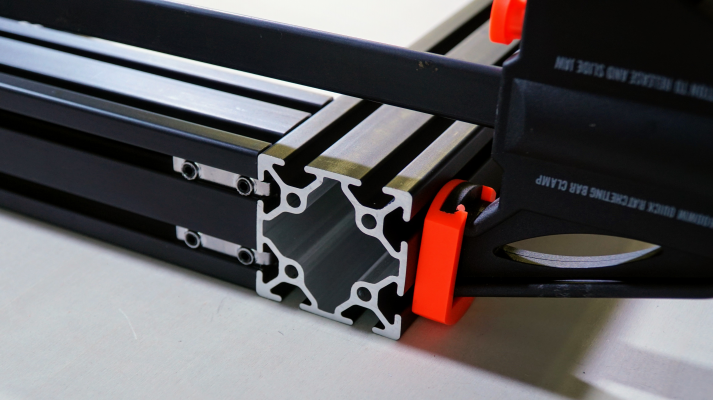
The corner posts and bottom rail took a little figuring out. The bottom 2 angle brackets are actually hidden by the bottom rail itself.
I had to use a short piece of 25x50 extrusion to place the bottom brackets, lock them in place, then slide the bottom rail over them.
Long clamps help. You're looking at the bottom of the corner post.
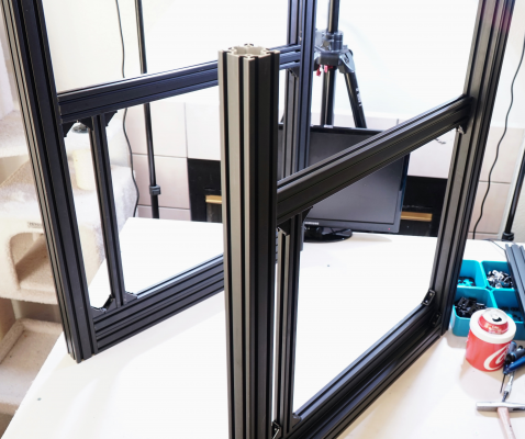
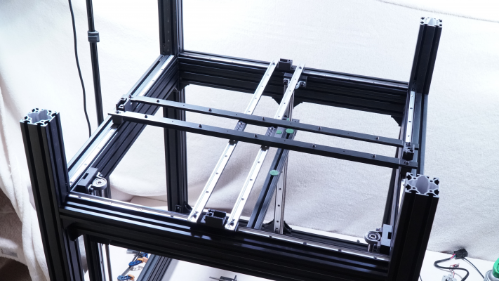
The left and right side panels done. The print bed is going to be a 3 point mount. The two 25x25 extrusions you see towards the front of the panels and one not in place yet in the center of the back panel will have the guide rails and lead screws mounted to them.
Here's what the left side will look like. The weight of the bed is mostly supported by the two bearings and only partially by the motor.
More to come!
|
Re: Black Beauty Build Log May 28, 2018 02:18AM |
Registered: 8 years ago Posts: 5,232 |
|
Re: Black Beauty Build Log May 28, 2018 10:04AM |
Registered: 7 years ago Posts: 257 |
|
Z Axis Supports May 28, 2018 02:04PM |
Registered: 6 years ago Posts: 90 |
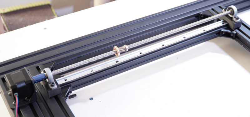
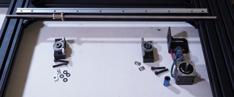
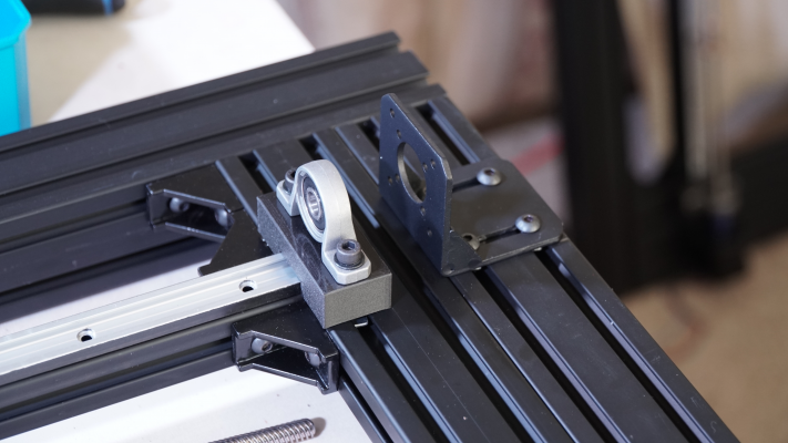
Here are the parts I used for the Z axis supports.
The bottom of the frame is on the right.
I'm still thinking about how to actually mount the bed to the lead screw nut and the rail carriage. The Duet has the ability to level the bed by itself when it has control of 3 motors but that means that the joints between the bed and the screw and carriage have to be a little flexible.
You can see the 3-point arrangement here:
|
Re: Black Beauty Build Log May 28, 2018 03:46PM |
Registered: 9 years ago Posts: 31 |
You mention that you're using CF-HTPLA for the printed parts-- I'm interested to see how that will end up working out in the long run. PLA is known for having high creep properties (see, for example, here), which typically make it a poor choice for structural and mechanical applications. However, it is possible that the fiber-fill helps in this regard (a bit of googling found this vaguely relevant paper, note in particular: "the addition of bamboo fiber to neat PLA significantly improved creep resistance, due to the better stiffness and heat conduction of bamboo fiber."). I'm curious how much the fiber-fill and annealing improve material properties relative to "regular" PLA, and whether these improvements are significant enough to make the material a viable choice for mechanical parts relative to ABS, PC, etc.
Edited 1 time(s). Last edit at 05/28/2018 03:47PM by NathanaelXYZ.
Edited 1 time(s). Last edit at 05/28/2018 03:47PM by NathanaelXYZ.
|
Re: Black Beauty Build Log May 29, 2018 04:00PM |
Registered: 6 years ago Posts: 90 |
Quote
NathanaelXYZ
You mention that you're using CF-HTPLA for the printed parts-- I'm interested to see how that will end up working out in the long run.
With the new design, I no longer have to print my own motor and pulley mounts and they would have been the ones to suffer from any creep. The printed parts left are the center tool mount plate, the 4 perimeter rail carriages, and the bearing standoff blocks pictured above. The bearing blocks are definitely under stress and I'm hoping that the annealing and carbon fiber will keep them stable. If not, I guess I can always have them machined out of aluminum. The other parts aren't really under much stress at all and the stuff I built for the prototype 8 months ago has been perfectly stable. I'll be keeping an eye on them though.
|
Z Axis Supports June 03, 2018 12:40PM |
Registered: 6 years ago Posts: 90 |
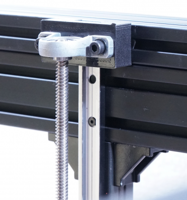
I made a little design change to the Z axis arrangement to make it more stable and easier to work with. The rail and screw are now offset which makes securing the rail carriage to the bracket easier:
I now have to recant my previous statement concerning the use of plastic parts. I was originally going to use only aluminum extrusion bits for the bed support but cutting and tuning the aluminum was too difficult so I went back to a carbon fiber approach which allows better adjustability.
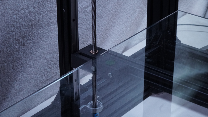
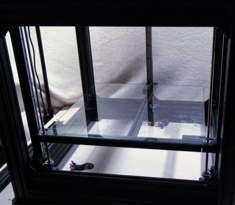
The bed is a piece of 510 x 510 x 6 mm tempered glass and will be covered with a 500x500 piece of PrintBite+ which should be arriving with my Flex3Drive hopefully next week.
The glass is almost 4kg which is kinda heavy but with 3 2amp steppers it should be ok. I'll be testing before I apply the PrintBite+ so I can swap it out with a 3mm thick piece instead if I have to.
I'm still trying to decide on bed heaters. 1 500x500 heater would be a waste of power for most prints so I'm thinking about maybe 2 or 4 so I can only power the surface area I need.
I now have to recant my previous statement concerning the use of plastic parts.
 I was originally going to use only aluminum extrusion bits for the bed support but cutting and tuning the aluminum was too difficult so I went back to a carbon fiber approach which allows better adjustability.
The bed is a piece of 510 x 510 x 6 mm tempered glass and will be covered with a 500x500 piece of PrintBite+ which should be arriving with my Flex3Drive hopefully next week.
The glass is almost 4kg which is kinda heavy but with 3 2amp steppers it should be ok. I'll be testing before I apply the PrintBite+ so I can swap it out with a 3mm thick piece instead if I have to.
I'm still trying to decide on bed heaters. 1 500x500 heater would be a waste of power for most prints so I'm thinking about maybe 2 or 4 so I can only power the surface area I need.
|
Re: Black Beauty Build Log June 03, 2018 01:11PM |
Registered: 11 years ago Posts: 5,780 |
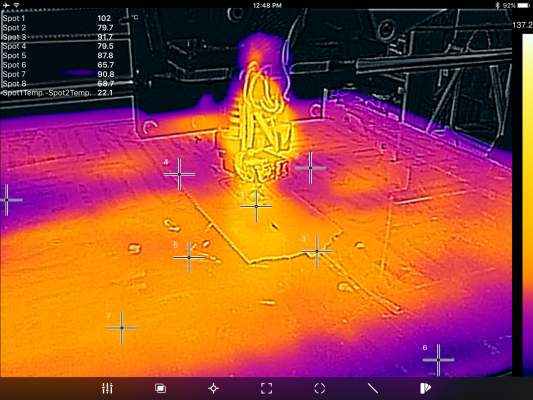
Applying a heater directly to a glass bed is a bad idea, especially a thick glass bed. Glass is a thermal insulator. That means it doesn't heat evenly. If you want prints to stick, you want even heat.
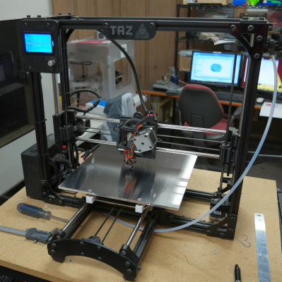
Here's a Taz printer at the makerspace that had a heater attached directly to a glass bed.
Notice the 30+C variation in temperature across the surface. We used to have all sorts of problems getting prints to stick to that.
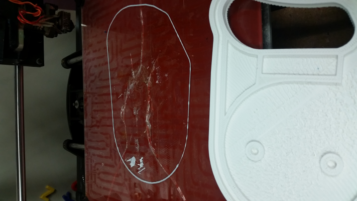
The glass eventually did what all glass does (it broke)
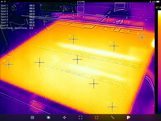
and I replaced it with a piece of 1/4" thick cast aluminum tooling plate (and added a thin layer of PEI), reusing the heater that we managed to peel off the shards of broken glass. I also converted it from 4 point bending to 3 point leveling at the same time.
No more prints letting go of the bed, and no need to tweak the bed leveling every couple prints.
Ultra MegaMax Dominator 3D printer: [drmrehorst.blogspot.com]
|
Re: Z Axis Supports June 03, 2018 06:23PM |
Registered: 10 years ago Posts: 14,672 |
Another reason not to use tempered glass is that the tempering process tends to warp the glass. If you want to use glass beds, use an aluminium heat spreader beween the heater and the glass, with ordinary 4mm float glass on top. This is what 2 of my 3 printers use.
Large delta printer [miscsolutions.wordpress.com], E3D tool changer, Robotdigg SCARA printer, Crane Quad and Ormerod
Disclosure: I design Duet electronics and work on RepRapFirmware, [duet3d.com].
Large delta printer [miscsolutions.wordpress.com], E3D tool changer, Robotdigg SCARA printer, Crane Quad and Ormerod
Disclosure: I design Duet electronics and work on RepRapFirmware, [duet3d.com].
|
Re: Black Beauty Build Log June 03, 2018 08:19PM |
Registered: 6 years ago Posts: 90 |
Yep, 3 point support is the way to go. Almost impossible to deform or break a bed that way as long as the bed can float slightly on its supports.
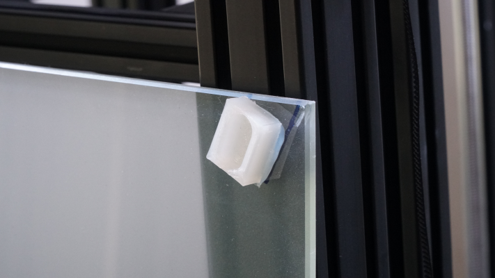
Tempered glass wasn't my first choice. I've been trying to find a fabricator nearby that can provide a reasonably flat piece of 6061 but no such luck, at least at a reasonable price. You'd think it'd be an easy thing to source. Anyway, I'm still looking and at least it'd be easy to swap out. There are 3 clamps (not shown in the pics above) that hold the plate in place.
Tempered glass wasn't my first choice. I've been trying to find a fabricator nearby that can provide a reasonably flat piece of 6061 but no such luck, at least at a reasonable price. You'd think it'd be an easy thing to source. Anyway, I'm still looking and at least it'd be easy to swap out. There are 3 clamps (not shown in the pics above) that hold the plate in place.
|
The Dremel gods have demanded a sacrifice... June 03, 2018 08:23PM |
Registered: 6 years ago Posts: 90 |
The Dremel gods are not forgiving of inattention.
Luckily, my valiant and brave t-shirt hurled itself in the path of the oncoming tungsten carbide cutter and gave its short life so that it's master's bacon might stay intact.
Luckily, my valiant and brave t-shirt hurled itself in the path of the oncoming tungsten carbide cutter and gave its short life so that it's master's bacon might stay intact.
|
The XY gantry is back in place June 03, 2018 08:29PM |
Registered: 6 years ago Posts: 90 |
Got the XY gantry back in place. Even with the extra span, it's pretty solid.
Steppers and idler pulleys are next hopefully in the next two days. Although I don't have the Fled3Drive yet, I do have a BLTouch I can mount to the tool carriage and since all the wiring and electronics are being reused from the prototype, I should at least be able to partially test accuracy in all 3 axes by mid week.
Steppers and idler pulleys are next hopefully in the next two days. Although I don't have the Fled3Drive yet, I do have a BLTouch I can mount to the tool carriage and since all the wiring and electronics are being reused from the prototype, I should at least be able to partially test accuracy in all 3 axes by mid week.
|
Re: Black Beauty Build Log June 04, 2018 07:40AM |
Registered: 11 years ago Posts: 5,780 |
The bed shouldn't be "floating" on the springs, and they aren't there to protect against a "head-crash". They are there to ensure that the bed is pushed firmly against the heads of the leveling screws (or the nuts, depending on how you've assembled things).
I used a kinematic mount for the bed in my last printer- the springs hold the bed down on the leveling screws instead of pushing it up. In theory, gravity alone is sufficient to keep the bed in position, but I transport the machine laying on its back and needed the springs to ensure it would stay put. I print on a 0.7 mm thick piece of PEI stuck to the aluminum bed plate. The kinematic mount allows the bed to expand without creating any lateral forces that cause things to bend. See: [drmrehorst.blogspot.com]
That tee-shirt is why I always work naked, protected by a thick layer of vaseline....
Ultra MegaMax Dominator 3D printer: [drmrehorst.blogspot.com]
|
Re: Black Beauty Build Log June 04, 2018 10:14AM |
Registered: 6 years ago Posts: 90 |
Quote
the_digital_dentist
The bed shouldn't be "floating" on the springs, and they aren't there to protect against a "head-crash". They are there to ensure that the bed is pushed firmly against the heads of the leveling screws (or the nuts, depending on how you've assembled things).
The bed as shown is resting on thin felt pads both to prove for a bit of movement and to provide a thermal break between the glass and the aluminum and plastic. I was still thinking about how to provide for expansion.
Quote
the_digital_dentist
I used a kinematic mount for the bed in my last printer- the springs hold the bed down on the leveling screws instead of pushing it up. In theory, gravity alone is sufficient to keep the bed in position, but I transport the machine laying on its back and needed the springs to ensure it would stay put. I print on a 0.7 mm thick piece of PEI stuck to the aluminum bed plate. The kinematic mount allows the bed to expand without creating any lateral forces that cause things to bend. See: [drmrehorst.blogspot.com]
Ah, that's a great solution! Even if I have to stick with the glass, I could epoxy some aluminum (or even nylon) bits with slots or countersinks to the bottom of the surface and mount the ball ends in the support extrusions.
Quote
the_digital_dentist
That tee-shirt is why I always work naked, protected by a thick layer of vaseline....
I'm going to have that picture burned into my brain for a while now, thanks.

|
Re: Black Beauty Build Log June 04, 2018 10:58AM |
Registered: 11 years ago Posts: 5,780 |
Most glass doesn't expand much at the temperatures a print bed operates, so it may not be needed. OTOH, if you use glass on top of a piece of aluminum you have to think about what the aluminum is going to do.
Ultra MegaMax Dominator 3D printer: [drmrehorst.blogspot.com]
Ultra MegaMax Dominator 3D printer: [drmrehorst.blogspot.com]
|
Re: Black Beauty Build Log June 04, 2018 11:27AM |
Registered: 6 years ago Posts: 90 |
Quote
the_digital_dentist
Most glass doesn't expand much at the temperatures a print bed operates, so it may not be needed. OTOH, if you use glass on top of a piece of aluminum you have to think about what the aluminum is going to do.
Yeah true but your mount also allows a plate of any material to tilt and follow the lead screws without putting any stress on the plate itself.
|
Re: Black Beauty Build Log June 12, 2018 06:33PM |
Registered: 6 years ago Posts: 90 |
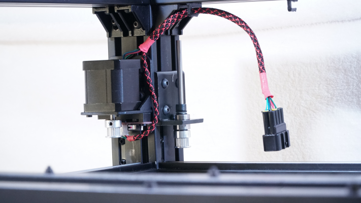
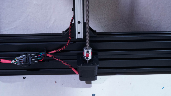
Motors and idler pulleys mounted and connectorized.
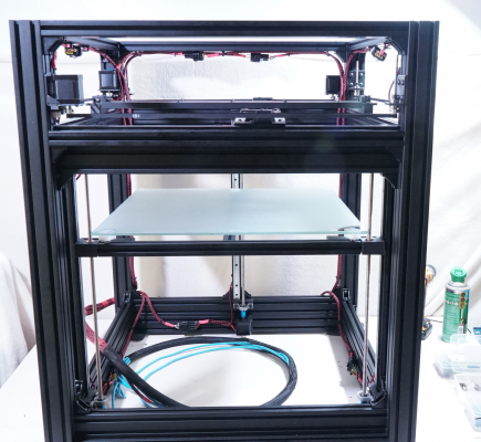
Here's the new bed mount. These are 11mm ball ends for RC car linkages.
I printed 2 sliding races from nylon for the front 2 corners, The center back race is circular to anchor the bed. The front 2 races "point" to the center back one. Since they're at a diagonal, the bed can only move in a straight line from the center back to the corners which it can't do normally.
Cabling done
Now it's time to connectorize the cables, fire up the Duet2, test the endstops, and test the motors.
Where did I put that fire extinguisher?
I'm still waiting on the Flex3Drive and I'm still trying to find an aluminum plate for the bed. For now I'll just stick to the glass. I don't have to mount the heaters until I get the Flex3Drive anyway. I do have the BLTouch though so I'll be mounting that and testing until then. The frosting on the glass is just a spray-on protective coating, FYI.
The one major thing I wish I'd done differently is putting the frame on 2 saw horses instead of a table so I could stand up inside it. It would have made things so much easier. I still feel like the guy who built a boat in his basement though. I need to find a permanent home for this thing.
|
Re: Black Beauty Build Log June 13, 2018 12:04AM |
Registered: 11 years ago Posts: 5,780 |
It looks pretty good. When will it be printing?
Ultra MegaMax Dominator 3D printer: [drmrehorst.blogspot.com]
Ultra MegaMax Dominator 3D printer: [drmrehorst.blogspot.com]
|
Re: Black Beauty Build Log June 13, 2018 11:37AM |
Registered: 6 years ago Posts: 90 |
Quote
the_digital_dentist
It looks pretty good. When will it be printing?
Thanks.
I had everything hooked up to the Duet2 last night (after I re-pinned 6 connectors I screwed up) and gave the XY axes a workout.
I have to re-route some cables though as the ones that come down the inside corners in the back are being hit by the tool carriage. I'll have to route them on the outside.
The Z axis will be tested today and I'll mount the BLTouch and probe the bed today as well. I hope.
I still haven't heard back from @Mutley3D on my Flex3Drive so I guess they're swamped. If I don't hear back this week, I'll try and mount a bowden setup temporarily.
I'm making final calls on aluminum plate today. I called 3 places early last week and all 3 said "We'll get back to you". None did. You'd think I was asking for gold plated aluminum. If I can't get responses from them, I'll go ahead and order the heaters tomorrow. I just don't want to stick them to the glass then have to pull them off again. Speaking of the glass...one other task for today is to use a heater I do have (not the correct size) and do a test with my Flir to see how evenly the glass heats.
So to answer your question... early next week maybe?
|
Re: Black Beauty Build Log June 13, 2018 03:09PM |
Registered: 11 years ago Posts: 5,780 |
You can print PLA on unheated blue painter's tape for testing without the bed heater.
Ultra MegaMax Dominator 3D printer: [drmrehorst.blogspot.com]
Ultra MegaMax Dominator 3D printer: [drmrehorst.blogspot.com]
|
Re: Black Beauty Build Log June 13, 2018 03:38PM |
Registered: 6 years ago Posts: 90 |
Quote
the_digital_dentist
You can print PLA on unheated blue painter's tape for testing without the bed heater.
True.
I did my Flir analysis of the 1/4" tempered glass over lunch. The results were so dismal I'm not even going to show them. I managed to get a response on an aluminum plate just a few minutes ago but he quoted me $460 for a mic 6 plate which is not in my budget.
 He's exploring other alternatives with a flatness between 50 and 100 microns.
|
Re: Black Beauty Build Log June 13, 2018 03:51PM |
Registered: 11 years ago Posts: 5,780 |
Are you having someone machine a plate for you? I can't imagine why a piece of aluminum plate would cost that much. The local Speedy Metals retailer sells 12"x12" x 1/4" MIC6 for $40 the last time I checked, so a 500x500 piece should be about 3x that. There are plenty of ebay suppliers who sell for about the same price.
I picked up the 13.5" x 15" x 8mm (yes, I know, mixed units) MIC6 plate that became the bed in UMMD for $15 at a local metals supplier who sells cutoffs for scrap price. See: [www.howardprecision.com]
Ultra MegaMax Dominator 3D printer: [drmrehorst.blogspot.com]
I picked up the 13.5" x 15" x 8mm (yes, I know, mixed units) MIC6 plate that became the bed in UMMD for $15 at a local metals supplier who sells cutoffs for scrap price. See: [www.howardprecision.com]
Ultra MegaMax Dominator 3D printer: [drmrehorst.blogspot.com]
|
Re: Black Beauty Build Log June 13, 2018 03:59PM |
Registered: 11 years ago Posts: 5,780 |
It might be a better investment to go cheap on the bed plate and use mesh compensation for any unflatness in the controller. With a plate that size 3 points might not be enough to support it, depending on the layer thicknesses you intend to print.
Ultra MegaMax Dominator 3D printer: [drmrehorst.blogspot.com]
Ultra MegaMax Dominator 3D printer: [drmrehorst.blogspot.com]
I can "Air Print"  June 15, 2018 09:33PM |
Registered: 6 years ago Posts: 90 |
Made lots of progress...
I found a local place that'll give me a 20" x 20" x 1/4" MIC-6 plate for $176. Should be ready mid next week.
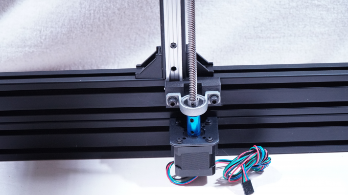
I made a design change to the bottom end of the Z lead screws. Having a bearing block right above the motor was introducing wobble in the screw so I got rid of it. I also changed out the couplers because the rigid ones weren't grabbing the lead screw evenly which also contributed to the wobble. I'm a little concerned that the weight of the bed is now only carried by upper bearing and the motor but we'll see.
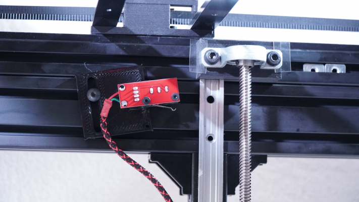
I am also getting rid of the upper (min) Z endstops now that I've got the BLTouch working. It's just hanging off to the side now. I may use them as Z max endstops. We'll see.
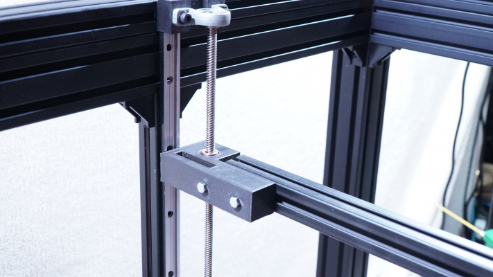
You can also see that I had to shim the upper bearing block to get rid of more wobble. Now if I lower the bed all the way then raise it at 1000 mm/m you can see absolutely no wobble in the screws.
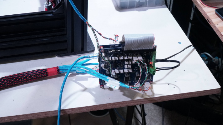
The Duet2 + Duex5 wired up. The 2 motors connected to the Duex5 are actually the X1 and Y1 motors.
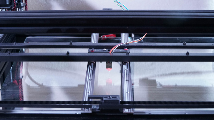
I still don't have the Flex3Drive but I mounted the BLTouch in the center of the tool carriage.
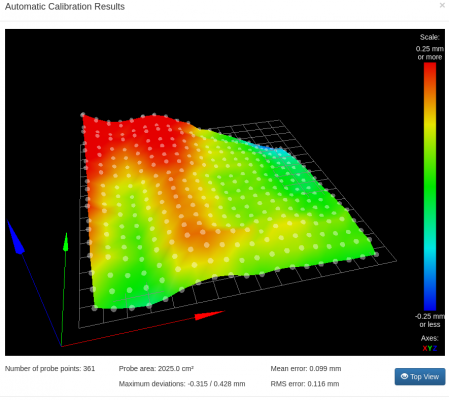
Z homing using the BLTouch is working perfectly as is auto bed levelling and mesh grid compensation.
I guess the glass IS a little wavey
I'm still tweaking of course but I can "air print" now.
I may change out the lead screw backlash nuts for delrin ones. Not that the backlash bits were needed anyway but they're not as tight side-to-side as I'd like.
I also have to change out the bearings on the XY sliders. I accidentally put ones in that float in the Z axis so the sliders wobble a bit. There's not enough weight to keep them flat.
Mutly3D where are you??? I need that Flex3Drive!
Edited 1 time(s). Last edit at 06/15/2018 09:35PM by gtj.
I found a local place that'll give me a 20" x 20" x 1/4" MIC-6 plate for $176. Should be ready mid next week.
I made a design change to the bottom end of the Z lead screws. Having a bearing block right above the motor was introducing wobble in the screw so I got rid of it. I also changed out the couplers because the rigid ones weren't grabbing the lead screw evenly which also contributed to the wobble. I'm a little concerned that the weight of the bed is now only carried by upper bearing and the motor but we'll see.
I am also getting rid of the upper (min) Z endstops now that I've got the BLTouch working. It's just hanging off to the side now. I may use them as Z max endstops. We'll see.
You can also see that I had to shim the upper bearing block to get rid of more wobble. Now if I lower the bed all the way then raise it at 1000 mm/m you can see absolutely no wobble in the screws.
The Duet2 + Duex5 wired up. The 2 motors connected to the Duex5 are actually the X1 and Y1 motors.
I still don't have the Flex3Drive but I mounted the BLTouch in the center of the tool carriage.
Z homing using the BLTouch is working perfectly as is auto bed levelling and mesh grid compensation.
I guess the glass IS a little wavey

I'm still tweaking of course but I can "air print" now.
I may change out the lead screw backlash nuts for delrin ones. Not that the backlash bits were needed anyway but they're not as tight side-to-side as I'd like.
I also have to change out the bearings on the XY sliders. I accidentally put ones in that float in the Z axis so the sliders wobble a bit. There's not enough weight to keep them flat.

Mutly3D where are you??? I need that Flex3Drive!
Edited 1 time(s). Last edit at 06/15/2018 09:35PM by gtj.
Re: I can "Air Print"  June 16, 2018 02:08AM |
Registered: 8 years ago Posts: 5,232 |
Re: I can "Air Print"  June 16, 2018 06:58AM |
Registered: 10 years ago Posts: 14,672 |
It looks like you have a slight twist in your gantry too, unless it's the glass again.
Large delta printer [miscsolutions.wordpress.com], E3D tool changer, Robotdigg SCARA printer, Crane Quad and Ormerod
Disclosure: I design Duet electronics and work on RepRapFirmware, [duet3d.com].
Large delta printer [miscsolutions.wordpress.com], E3D tool changer, Robotdigg SCARA printer, Crane Quad and Ormerod
Disclosure: I design Duet electronics and work on RepRapFirmware, [duet3d.com].
Sorry, only registered users may post in this forum.
