First build, having issues
Posted by LFG
|
First build, having issues October 09, 2018 08:25PM |
Registered: 5 years ago Posts: 26 |
Well I am 4-month into this current rabbit hole of 3D printing. I Have 2 Anet A8 builds that were up and running when I decided to convert them to Extruded Aluminum cube frames.
I completed (mostly) the first conversion about 3 weeks ago and decided that I'd build a 3rd printer before converting the 2nd Anet because I had over purchased so many parts. To that end now I have the printer about 85% done and I'm in the process of getting the electronics functioning but that's where my luck has "up and left the building". I have search the forums and have identified a few of y issues but I didn't realize that the Arduino Mega and Ramps 1.4 would require me to learn so much about electronics.
So here are the problems.
1. I am trying to run a RepRap Discount Full Graphic Smart Controller which function fine when I'm plugged into the Mega but once I upload and disconnect the LCD turns off even though the printer is still on.
2. The end stops are driving me crazy. I am not 100% sure I have them right and that is partly due to not really being able to test them in a homing situation. I have what I believe are mechanical roller endstops. They are little black rectangular boxes with three blade connections coming out of the bottom. I have them wire wit a red on the C(1) blade an a black on the NO(2) blade. These wires are then connected to the associated X/Y/Z min end stop pins with the red connected to the negative (-) on the Ramps and the black connected to the signal (S). Is this correct for the normally open configuration? On a side note I can't find a forum thread that discusses the difference between this style and the ones attached to a PCB. Are the PCB ones the same or are they fundamentally different?
3. The biggest problem I have is the steppers are not homing correctly. The problem is the X-stepper powers whines an shudders for a second them powers down. The Y-stepper then whines and shudders for a second an then powers down. Then the Z-stepped power up the left twists 1/4 turn clockwise, the right twists 1/4 turn counterclockwise whine like a cat in a blender and both shudder for 2 second then power down.
I am using A4988 Stepper Driver Shields with the pots oriented away from the power side of the ramps board. I have repeatedly checked the coil loops for the steppers (they came without plugs attached) and have confirmed the correct pairs. I have also confirmed that the pairs are wired correctly on the ramps board in the 2A, 2B, 1B, 1A configuration, though for the life of me I can't see how I am supposed to know the A's from the B's. I am assuming that I have blown the RAMPS or the MEGA but I can get the X-stepper and Y-steppers to move under the move axis menu in the LCD so I am not sure how bad it all is. I even swapped the extruder stepper with the right (whining cat) Z-stepper and under the move axis menu I ha it mostly turning in conjunction with the left Z-stepper.
I am really at a loss here as I would think that having the stepper rotating in opposite directions would indicate a stepper was bad. But once I permanently moved the extruder to the right Z-stepper position an tried to home it went right back to blending the cat.
I have tried 2 different ramps boards and arduino mega's, both with the same result. I even tested the 2nd ramps setup before connecting it to the printer by using the test config file for the ramps board and confirmed all operations were correct. I have two more of each board but I am reluctant to run anything before I get some more confidence in my understanding of the wiring/programming.
I can only assume I have hacked up the config h file incorrectly. Please let me know,
LFG
The Lazy Fat Guy!
|
Re: First build, having issues October 09, 2018 11:33PM |
Registered: 11 years ago Posts: 5,780 |
1) the LCD gets power from 5V on the arduino or RAMPS board. If you have USB connected, it gets power via USB. If you disconnect USB, and the LCD goes dead, the 5V regulator on the arduino or RAMPS board is probably dead (that happens a lot).
2) it is best to wire endstops in the NC configuration. That way if a cable breaks, the machine will stop running until you fix the cable. The locations of the switches determines whether they plug into the min or max endstop inputs. More on that topic here: [drmrehorst.blogspot.com]
3) It sounds like you either set the current for the motors too high and the drivers are over heating and shutting down or you're trying to drive them too fast, or both.
Those little stepper driver modules are a terrible design that can't dissipate heat the ICs, so you have to keep motor current set pretty low. Better get a bunch of spare modules because you're going to need them. If you don't burn them up you'll break the current setting pots.
Edited 1 time(s). Last edit at 10/09/2018 11:52PM by the_digital_dentist.
Ultra MegaMax Dominator 3D printer: [drmrehorst.blogspot.com]
|
Re: First build, having issues October 10, 2018 12:53AM |
Registered: 8 years ago Posts: 5,232 |
The difference in PCB endstops and simple switches is: the switches need internal pullup resistors enabled in Marlin.
You can test them with the M119 command sent from a PC-host program like Pronterface or Repetier host.
When they report 'triggered' although they are not pressed, you also have to invert the endstop-logic in Marlin.
Even when you found the right coils from your stepperwires, you have to sort them in the right order or they just hum/vibrate. The classic order is: black, green, blue, red.
If the motors run in different direction, turn around the whole plug on Ramps or revers stepper direction in Marlin.
Edited 1 time(s). Last edit at 10/10/2018 12:54AM by o_lampe.
|
Re: First build, having issues October 10, 2018 08:18PM |
Registered: 5 years ago Posts: 26 |
Please bear with me I'm a civil engineer. I can calc you storm water and size a foundation but I have no idea what you mean when you say enable internal pullup resistors. Are you saying to un-comment the X/Y/Z min endstop pullup in the marlin code as shown below?
// Enable pullup for all endstops to prevent a floating state
#define ENDSTOPPULLUPS
#if DISABLED(ENDSTOPPULLUPS)
  // Disable ENDSTOPPULLUPS to set pullups individually
  //#define ENDSTOPPULLUP_XMAX
  //#define ENDSTOPPULLUP_YMAX
  //#define ENDSTOPPULLUP_ZMAX
  #define ENDSTOPPULLUP_XMIN
  #define ENDSTOPPULLUP_YMIN
  #define ENDSTOPPULLUP_ZMIN
  //#define ENDSTOPPULLUP_ZMIN_PROBE
#endif
// Enable pullup for all endstops to prevent a floating state
#define ENDSTOPPULLUPS
#if DISABLED(ENDSTOPPULLUPS)
// Disable ENDSTOPPULLUPS to set pullups individually
//#define ENDSTOPPULLUP_XMAX
//#define ENDSTOPPULLUP_YMAX
//#define ENDSTOPPULLUP_ZMAX
#define ENDSTOPPULLUP_XMIN
#define ENDSTOPPULLUP_YMIN
#define ENDSTOPPULLUP_ZMIN
//#define ENDSTOPPULLUP_ZMIN_PROBE
#endif
|
Re: First build, having issues October 10, 2018 11:20PM |
Registered: 5 years ago Posts: 26 |
OK. witched to NC endstop config. re-oriented the red and blue pair and enabled pullups as noted above. haven't homed yet. Had to flip orientation of all stepper plugs to reverse directions. X-axis responding correctly, though heat sink of stepper got hot fast. Y axis responded correctly. Z got much better but still jerks funny and screams when moving. Pretty sure step setting is off and that I need to slow down the movement speed.
I know I have seen direction in the forums before and I will keepp looking but if somone was /is feeling kind could you confirm that what I should do is change:
#define DEFAULT_MAX_FEEDRATE { 300, 300, 5, 25 }
to something like:
#define DEFAULT_MAX_FEEDRATE { 200, 200, 2, 25 }
The Lazy Fat Guy!
I know I have seen direction in the forums before and I will keepp looking but if somone was /is feeling kind could you confirm that what I should do is change:
#define DEFAULT_MAX_FEEDRATE { 300, 300, 5, 25 }
to something like:
#define DEFAULT_MAX_FEEDRATE { 200, 200, 2, 25 }
The Lazy Fat Guy!
|
Re: First build, having issues October 11, 2018 01:21AM |
Registered: 8 years ago Posts: 5,232 |
Quote
LFG
Please bear with me I'm a civil engineer. I can calc you storm water and size a foundation but I have no idea what you mean when you say enable internal pullup resistors. Are you saying to un-comment the X/Y/Z min endstop pullup in the marlin code as shown below?
// Enable pullup for all endstops to prevent a floating state #define ENDSTOPPULLUPS #if DISABLED(ENDSTOPPULLUPS) // Disable ENDSTOPPULLUPS to set pullups individually //#define ENDSTOPPULLUP_XMAX //#define ENDSTOPPULLUP_YMAX //#define ENDSTOPPULLUP_ZMAX #define ENDSTOPPULLUP_XMIN #define ENDSTOPPULLUP_YMIN #define ENDSTOPPULLUP_ZMIN //#define ENDSTOPPULLUP_ZMIN_PROBE #endif
If you have no quotes on the first line, all endstop pullups are activated. The other lines are obsolete then.
The new max. speed settings are OK.
You might want to calibrate stepper Vref to match your drivers and steppers first.
|
Re: First build, having issues October 11, 2018 08:22PM |
Registered: 5 years ago Posts: 26 |
Thanks for the link with the calculations.
Few questions:
Where do I get the current limit used in the calculation from? (is it the 0.9A listed in the stepper description?)
I assume I have Chinese knockoffs with a Rs=0.1, is there a way to check?
On a different topic I purchased 0.9deg Nema 17 Stepper Motor Bipolar 0.9A steppers. I assume that the 0.9deg means I need to adjust the step distance somewhere in the config H file.
The Lazy Fat Guy!
|
Re: First build, having issues October 11, 2018 09:52PM |
Registered: 5 years ago Posts: 26 |
Update:
I have adjusted the settings as listed below:
#define DEFAULT_AXIS_STEPS_PER_UNIT { 160, 160, 8000, 1000 } <---Doubled these due to 0.9deg steppers
#define DEFAULT_MAX_FEEDRATE { 200, 200, 2, 25 } <----Dropped these from 300, 300, 5, 25
#define DEFAULT_MAX_ACCELERATION { 3000, 3000, 100, 10000 } <---- Do I need to change these?
I also cranked the pots down and set them at a 1/4 turn from low point and commented out the individual end stop pullups as discussed above.
I checked X and Y and they worked great. Z axis screeched but turned.
I was able to home X and no problem but again Z sounds like a grinder is tearing the stepper up. The left and right lead screws are not always turning in the same direction. In fact, they did a little dance where they were switching back and forth trying to bind the axis. Does that make any sense to anyone?
Edited 2 time(s). Last edit at 10/11/2018 09:54PM by LFG.
The Lazy Fat Guy!
|
Re: First build, having issues October 11, 2018 11:00PM |
Registered: 11 years ago Posts: 5,780 |
8000 steps per mm in Z seems awfully high, as does 1000 for the extruder. Check your calculations.
Acceleration of 3000 in X and Y and 10k in the extruder is also pretty high to start. Try setting them to 500 for starters and then increase after you get things working.
Dual Z motors will get out of sync when you cycle power to the printer. You're going to want some means of resyncing them. Prusa runs the X axis up to the top of the Z axis and a little beyond to force the X axis to be perpendicular to the Z axis and force the screws back into sync.
Ultra MegaMax Dominator 3D printer: [drmrehorst.blogspot.com]
|
Re: First build, having issues October 11, 2018 11:12PM |
Registered: 5 years ago Posts: 26 |
I would agree that the numbers seem high. I have been looking for the discussions on calculating these number but have yet to find them. I just doubled the marlin defaults based on the .9deg vs 1.8deg steppers. I don't have a clue what to use as acceleration numbers. those are again the defaults.
Being parallel to the bed is not a thing I am currently concerned with as the twisting as the z steps drive in opposite direction renders that calibration pointless. The fact that they start in the same direction is what has me confused as its not just a cable plugged in or wired wrong.
The Lazy Fat Guy!
|
Re: First build, having issues October 12, 2018 01:22AM |
Registered: 8 years ago Posts: 5,232 |
Z-axis steps depend on leadscrew pitch and step angle. The default 4000 z-steps relate to 0.8mm pitch ( M5 leadscrew ) and 1.8 stepper.
You could disconnect the leadscrews and test the motors without load.
Regarding Vref: you should be able to read the value of the shunt resistors. ( or make an educated guess )
Here's an example of their location:
You could disconnect the leadscrews and test the motors without load.
Regarding Vref: you should be able to read the value of the shunt resistors. ( or make an educated guess )
Here's an example of their location:

|
Re: First build, having issues October 13, 2018 08:57PM |
Registered: 5 years ago Posts: 26 |
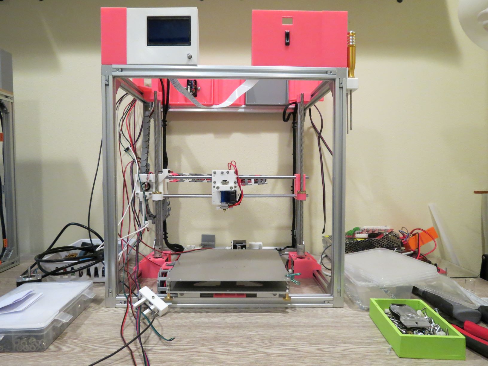
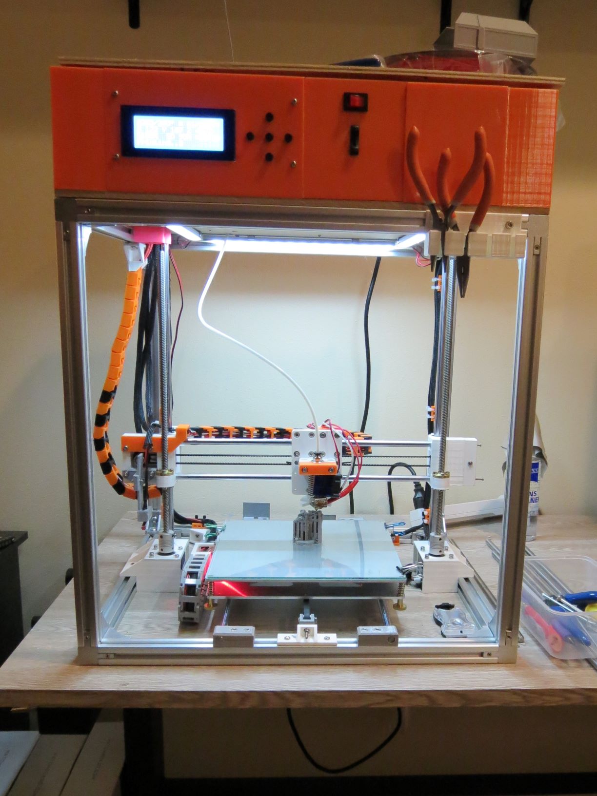
Figured I post some pics of the conversion and build.
Orange is still running on an Anet A8 board.
Pink is the second Anet which is supposed to go straight to a Ramps 1.4.
Gray , the 3rd printer is the one that is currently setup on a Ramps 1.4 with problems, as discussed above.
Looks like .1 is the correct Rs. So the math would look like this right?
Vref= 0.7 *8 *.1 = 0.56V
Steps calculated through Prusa site [www.prusaprinters.org]
X-Y = 200
Z = 800 {.9deg, 1:1 ratio, 2mm pitch w/4 starts (8mm lead screw pitch)}
UPDATE: tuned pots, uploader revised Marlin program. Still having issue. See youtube video upload for demo.
[youtu.be]
Edited 8 time(s). Last edit at 10/14/2018 11:24AM by LFG.
The Lazy Fat Guy!
Orange is still running on an Anet A8 board.
Pink is the second Anet which is supposed to go straight to a Ramps 1.4.
Gray , the 3rd printer is the one that is currently setup on a Ramps 1.4 with problems, as discussed above.

Looks like .1 is the correct Rs. So the math would look like this right?
Vref= 0.7 *8 *.1 = 0.56V
Steps calculated through Prusa site [www.prusaprinters.org]
X-Y = 200
Z = 800 {.9deg, 1:1 ratio, 2mm pitch w/4 starts (8mm lead screw pitch)}
UPDATE: tuned pots, uploader revised Marlin program. Still having issue. See youtube video upload for demo.
[youtu.be]
Edited 8 time(s). Last edit at 10/14/2018 11:24AM by LFG.
The Lazy Fat Guy!
|
Re: First build, having issues October 20, 2018 10:05PM |
Admin Registered: 13 years ago Posts: 7,000 |
lower the microstepping on the Z axis to 1/8th and adjust the steps/mm as well.
you may need to wire the Z steppers in series vs parallel [www.instructables.com]
you may need to wire the Z steppers in series vs parallel [www.instructables.com]
Sorry, only registered users may post in this forum.