Rep A Sketch
Posted by Number_5
|
Rep A Sketch November 18, 2018 12:59PM |
Registered: 5 years ago Posts: 62 |
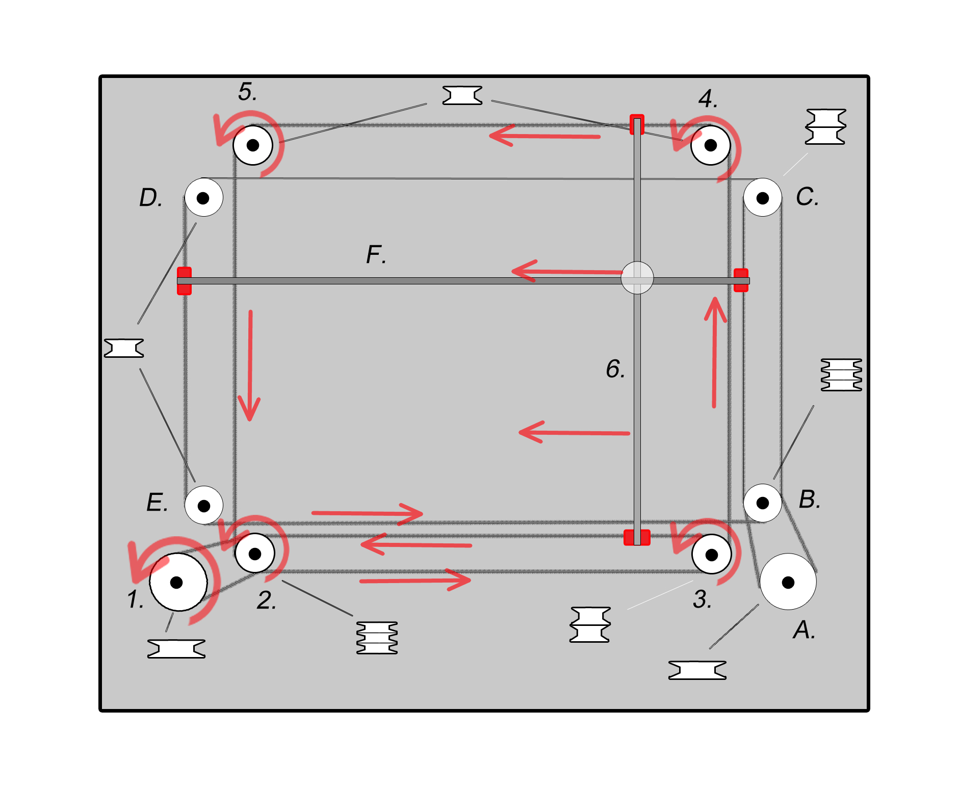
This is a thread documenting the build of a V-slot printer with Etch A Sketch kinematics. Similar to Ultimaker, but more akin to the original 2D drawing toy which doesnt have spinning rods like the Ultimaker does.
A few years back I was in the preliminary stage of designing my ideal printer that was like a mashup of the Ultimaker and another 3Dprinter whos name I can't seem to pronounce or recall. Ethustasious? lol something like that.
Anyhow that project kinda stalled out when it came time to actually trying to source all the parts for the rods and bearings, if you've shopped for 8mm rods before you know what I mean.
What did catch my eye was the extruded aluminum V-slot i3 coming from the far east. I thought I would give it a go, at the very least it was a cheap way to get a bunch of components.
It turned out to be a decent little printer. Using the frame as the linear guide is an elegant solution IMO.
Now I am going to have another go at it using V-slot and pulleys for the bearing surfaces instead of spinning rods and linear bearings. Linear guideways like HiWin were ruled out due to cost of a genuine product, the added weight and complexity of build were of little value.
Contrary to the fad of core XY machines, I will be using a direct drive BMG extruder with a V6. I've yet to print what I consider "fast", sure I've wanted things to be faster, but I don't think the speed that my extruder moves has ever been a limiting factor. A direct drive extruder seems to check more boxes as far as quality and material compatibility.
I am going to try and re-purpose some V-slot and wheels for the frame, though I may have to get more.
For electronics I have a Duet 2 Ethernet with a 7" panel Due, BLTouch and a 24V Meanwell power supply. Hopefully I have enough motors and leadscrews here, but I may have to get more depending on what I do with the Z axis. The build plate is 330 x 330 x 9.5mm cast aluminum,750w Keenovo heater and a PEI surface.
Height wise on the Z axis will be around 300mm-500mm.
I've attached a picture of Etch A Sketch kinematics from Wikipedia. It could basically be built just as it is in the picture, or have some of the pulleys stacked up more as I may have more space on the printer then you would in a relatively thin tablet like the Etch A Sketch.
|
Re: Rep A Sketch November 19, 2018 01:58AM |
Registered: 8 years ago Posts: 1,671 |
One of my first designs used the same kinematics, but with less parts as the motors replace the need for some of the details.
Couldnt quite decide how I was going to cure resin, but that wasnt as important as playing with iterations.
[reprap.org]
Edited 1 time(s). Last edit at 11/19/2018 05:19AM by MechaBits.
Couldnt quite decide how I was going to cure resin, but that wasnt as important as playing with iterations.

[reprap.org]
Edited 1 time(s). Last edit at 11/19/2018 05:19AM by MechaBits.
|
Re: Rep A Sketch November 19, 2018 06:46AM |
Registered: 5 years ago Posts: 62 |
Yup that is it.  I'll admit that design makes me consider using something different then extruded aluminum for the frame.
I broke the little fan for my E3D V6 last night. For some reason I thought I would check the fan to make sure that it was 24V.
When I was pushing it back on the nozzle, I must have been inadvertently pressing on the fan hub too much. I will have to order a replacement, I've also added a 40mm Nocuta to the cart. If I can get that to work I should, as the little 30mm E3D fan may end up being the loudest thing on my printer.
I'll admit that design makes me consider using something different then extruded aluminum for the frame. I broke the little fan for my E3D V6 last night. For some reason I thought I would check the fan to make sure that it was 24V.
When I was pushing it back on the nozzle, I must have been inadvertently pressing on the fan hub too much. I will have to order a replacement, I've also added a 40mm Nocuta to the cart. If I can get that to work I should, as the little 30mm E3D fan may end up being the loudest thing on my printer.
|
Re: Rep A Sketch November 21, 2018 10:02PM |
Registered: 5 years ago Posts: 62 |
I had the day off work today so I thought I would putter around with the build plate. The edges were really rough on two of the sides, so I went around them with a file and slightly broke the edges. It's not perfect but it's reasonable, I used a fairly coarse laminate plastic file. It worked pretty good but even it would get a small bit of aluminum stuck in the teeth that would leave a mark on the final pass. lol Good enough.
The build plate is left with a dimension of 334 x 336 x 9.6mm and weighs 2970 grams.
The build plate is left with a dimension of 334 x 336 x 9.6mm and weighs 2970 grams.

|
Re: Rep A Sketch November 22, 2018 03:12AM |
Registered: 8 years ago Posts: 1,671 |
|
Re: Rep A Sketch November 22, 2018 07:09AM |
Registered: 5 years ago Posts: 62 |
The metal files I had inside would clog up quickly with the aluminum, there was a lot of metal to remove. There might be a good one out in the garage somewhere, it was cold yesterday.
As far as the fan, small fans are notoriously loud, dimming a small fan isn't that practical. It would be hit or miss with the airflow and whether or not it starts at a reduced voltage. Noctua fans actually are fairly quiet by default, made to be dimmed to a degree so lets try it out for $19. I've watched a few videos of people using them on their Prusa with E3D, so at least I'm not venturing into uncharted waters.
As far as the fan, small fans are notoriously loud, dimming a small fan isn't that practical. It would be hit or miss with the airflow and whether or not it starts at a reduced voltage. Noctua fans actually are fairly quiet by default, made to be dimmed to a degree so lets try it out for $19. I've watched a few videos of people using them on their Prusa with E3D, so at least I'm not venturing into uncharted waters.
|
Re: Rep A Sketch November 22, 2018 07:41AM |
Registered: 11 years ago Posts: 5,780 |
Get something like this:
It will take sharp edges off metals and plastics. Great for deburring holes, too. The sharp, hardened steel blade swivels in the handle so it follows the contour of whatever you're deburring (straight edges and concavities). It's not so great for convex curves. Once you try one, you'll ask yourself how you ever lived without it.
If you get a 24V fan and run it on 15V (or a 12V fan running on 8V) it will turn very quietly and start reliably. A $2 buck converter can be used to drop the voltage.
When you shop for these things, you'll find many different ones, all with similar specs and prices. But they aren't all the same. The one linked above uses a multiturn trim pot to set the output voltage.
Cheaper/crappier ones use those same crappy, easily broken pots that are used on stepper driver modules.
Edited 1 time(s). Last edit at 11/22/2018 07:55AM by the_digital_dentist.
Ultra MegaMax Dominator 3D printer: [drmrehorst.blogspot.com]

It will take sharp edges off metals and plastics. Great for deburring holes, too. The sharp, hardened steel blade swivels in the handle so it follows the contour of whatever you're deburring (straight edges and concavities). It's not so great for convex curves. Once you try one, you'll ask yourself how you ever lived without it.
If you get a 24V fan and run it on 15V (or a 12V fan running on 8V) it will turn very quietly and start reliably. A $2 buck converter can be used to drop the voltage.
When you shop for these things, you'll find many different ones, all with similar specs and prices. But they aren't all the same. The one linked above uses a multiturn trim pot to set the output voltage.

Cheaper/crappier ones use those same crappy, easily broken pots that are used on stepper driver modules.

Edited 1 time(s). Last edit at 11/22/2018 07:55AM by the_digital_dentist.
Ultra MegaMax Dominator 3D printer: [drmrehorst.blogspot.com]
|
Re: Rep A Sketch November 22, 2018 08:05AM |
Registered: 5 years ago Posts: 62 |
|
Re: Rep A Sketch November 24, 2018 09:33PM |
Registered: 5 years ago Posts: 62 |
I did a bit of balancing of the build plate. The plate will be leveled at 3 points, it may also be lifted at 3 points. If so, these locations are reasonably balanced, they weigh approx 950-1000 grams at each location. (Build plate weighs just under 3 KG.)
One location is at the center of one edge of the X axis. The other two points of the triangle are 9cm back from the corners on the Y axis.
One location is at the center of one edge of the X axis. The other two points of the triangle are 9cm back from the corners on the Y axis.
|
Re: Rep A Sketch December 01, 2018 09:45PM |
Registered: 5 years ago Posts: 62 |
The build is officially underway I guess. I printed a cover for my Crydom D2425 SSR with a bit of T-glase. It's similar to a cover that is available, but I didn't want the terminal screw access holes in it, so I printed this one instead. I can just remove the cover if I need to get at the screws.
I also found a heat sink left over from a CPU that I will use. It still needs to be drilled and tapped for screw. Deut recommends a heat sink if your SSR is above around 25% of its current rating. I'm right at 25% using 6.25A of the available 25A, so I thought this would be fun.
I forgot to order a thermal pad to put between the SSR and heatsink, but I do have thermal grease here. The heatsink is obviously flat, the SSR is pretty good, but you can see a touch of daylight as it is a stamped part. They don't say you can't use thermal grease, so I think I will go with it.
There was a fan with the heatsink too, probably overkill but we will see what happens. It may depend on orientation and where it's installed I guess.

Sorry, only registered users may post in this forum.