Inverted T gantry printer
Posted by mcdanlj
|
Inverted T gantry printer April 05, 2020 04:29PM |
Registered: 6 years ago Posts: 61 |
I was pondering how to use a bunch of project leftovers and excess parts and re-usable bits from an otherwise junk printer to make a new printer with minimum of purchasing new vitamins. I believe I've got a design that requires me to purchase only a 100-tooth closed GT2 belt; I think everything else I can source from within my house.
To do this, I came up with a gantry mechanism that's a hybrid of a elements I've seen on gantry printers and gantry routers. So far, I haven't come up with the downsides that must exist... Usually when I have an idea that I haven't seen anyone else do before, there's a reason that I haven't seen it before.
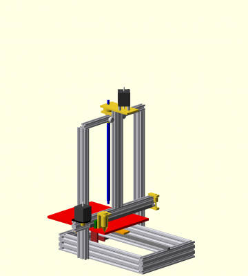
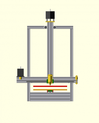
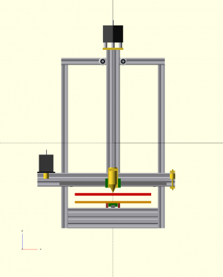
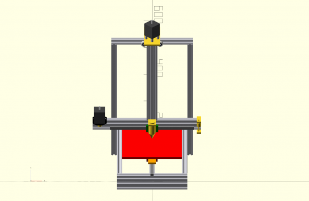
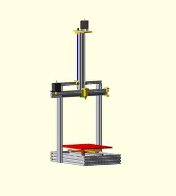
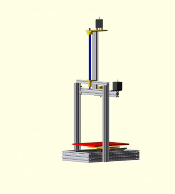
My design is hacked up in OpenSCAD with various libraries so it's not easy to play with (no IGES or STEP to point to), and it models only what I found necessary to be confident of fit generally, and that only well enough to give me that confidence. So lots of parts are missing from the model. But here are some renders and animated renders that should give the idea...
Thanks to the_digital_dentist I plan a kinematic mount though the adjusting blocks aren't in these renders; that's a solved problem.
First, here's an animation of all three axes moving together. Click on the pictures to see the animations. They aren't very useful without seeing them move!
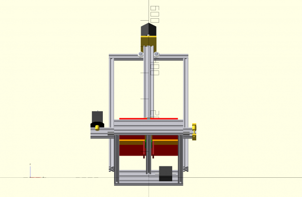
To show various perspectives, four animated renders, animating the rendering on different axes.
Here's the gantry raised to max Z to show which parts move when Z moves.
I'm interested in thoughts, questions, criticism, ideas, or information before I start cutting up my spare bits of v-slot! ☺
Edited 2 time(s). Last edit at 04/05/2020 06:12PM by mcdanlj.
|
Re: Inverted T gantry printer April 06, 2020 11:44AM |
Registered: 12 years ago Posts: 1,450 |
My most immediate impression is that the mass of the Z axis stepper is suspended on an inverted pendulum and Y movements may cause swaying and possibly racking. This is not to say that it won't work, just that you do need to pay attention to these forces and to find how to mitigate problems that you may get.
Mike
Mike
|
Re: Inverted T gantry printer April 06, 2020 03:36PM |
Registered: 6 years ago Posts: 61 |
Thank you! I had thought a little about this, but the question caused me to think more thoroughly.
There is a problem with me not having a STEP or IGES to upload. It's hard to see the tiny little wheels on the back side of the X rail in my animations. The two wheels on either side of the inverted T vertical section are easy to see in the front view, but there are also two wheels tucked in at the back side of the ends of the inverted T horizontal section running against the sides of the fixed vertical gantry sections. Those wheels are lined up as best I can with the head mass, so almost all of the head inertia is pushing through those wheels against the gantry sides. I hope.
If that's not stiff enough, I can rotate the fixed vertical gantry sections 90⁰ at the cost of 40mm more width (and looking even weirder), or even give in and actually buy some new parts — I could use a couple of sections of 4040 v-slot on the sides to stiffen the gantry sides more.
The closer it gets to max Z, the higher racking compliance (because less vertical distance between upper and lower Z wheels), so the more susceptibility to inverted pendulum forces. Having mass at the end should lower the native frequency of oscillation. My expectation is that the frequency of head movement won't be close to the resonant frequency, which will of course change with every Z movement. But I haven't done any analysis to demonstrate that, it's just... hope.
The next most obvious mitigation would be to simply print my tallest objects on my corexy printer and just have excess height in the design, reducing my 286mm maximum Z of this design to something smaller. Since the height was set by whatever ball screw was in my parts bin rather than by a concrete needs, that isn't actually crazy. (I so rarely print particularly large objects anyway.) As parts get taller on a moving-bed gantry printer, you have to start considering the inertia of the part as well as the inertia of the printer elements. On my corexy, I don't have that problem and so taller parts make more sense there anyway.
Finally, I could add a second fixed gantry stage with a second set of wheels above the existing gantry. It would technically then be overconstrained, but I don't think it would be a problem in practice. I'm unlikely to actually do that because for me the payout would probably be minimal.
|
Re: Inverted T gantry printer April 08, 2020 08:27AM |
Registered: 6 years ago Posts: 61 |
At MakerForums, Eric Lien (of HercuLien) convinced me to compare a cantilevered model: [forum.makerforums.info]
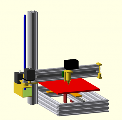
I had to change components to make that work with acceptable (to me) deflection. Here's another animation, again you'd have to click on it...
I can add a second tower and guide wheels to damp Z axis dynamics if they are a problem during infill or gap fill as Eric suggested. There's room to do it if I need it; I don't have to add it to the model.
So I'll give up on the weird gantry idea for now. The cantilever should work and will use less material. But it was fun to think through!
|
Re: Inverted T gantry printer April 08, 2020 01:33PM |
Registered: 8 years ago Posts: 1,671 |
|
Re: Inverted T gantry printer April 08, 2020 02:45PM |
Registered: 6 years ago Posts: 61 |
Quote
MechaBits
Your first idea could be enhanced with rods & bearings, or guides on the 2 columns, but still driven by one motor
If I understand your point correctly, the first does have guides on the columns, it's just hard to see them. There were, as guides, z-slot wheels on the back of the X rail against the towers, as well as z-slot wheels on the front against the middle vertical T member.
When I saw that max deflection with 1kg cantilevered at 0.3m station on 2060 was .01mm I was happier about moving to a cantilever design. Removes concerns about either binding or loosening depending on differences in coefficient of expansion between materials when heated in an enclosure. ☺
I think that the first idea would make sense if there were a reason to have an unusually wide bed, but I can't think of such a reason off the top of my head. ☺
|
Re: Inverted T gantry printer April 09, 2020 01:24AM |
Registered: 8 years ago Posts: 1,671 |
I was playing with a similar idea a few years back, motor was inverted from yours so didnt need the profile, also no profile on the X either.
|
Re: Inverted T gantry printer April 09, 2020 07:09AM |
Registered: 6 years ago Posts: 61 |
Oh, that makes a lot more sense than my original design! "Perfection is achieved, not when there is nothing more to add, but when there is nothing left to take away."
I think I'll end up sticking the the cantilever, if only because it turns out that it's a better match for my scrap bin; it lets me switch from using some pieces that I could easily use for other projects, to using a piece that I had no idea what I was going to do with. But if it has resonance issues, I can move to a gantry with a design something like that.
I've also switched in my latest version to direct drive instead of belt drive for Z, which would easily transport to your approach to a gantry.
|
Re: Inverted T gantry printer May 24, 2020 08:36AM |
Registered: 6 years ago Posts: 61 |
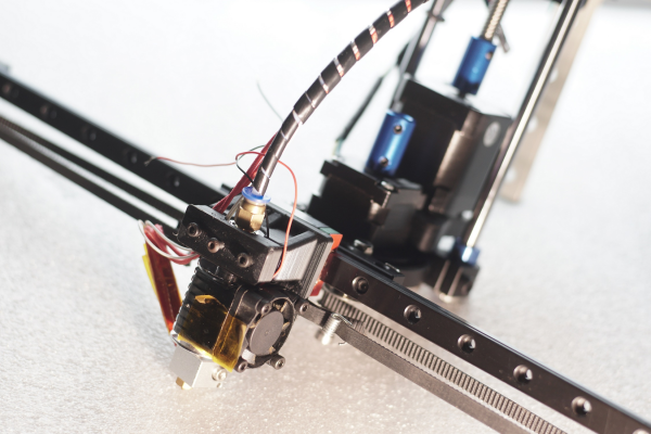
First plastic last night.
I've decided that even though DD puts his kinematic mount points across the middle of the bed, I prefer full bed length (as I did in my corexy printer). I may replace the bed support with one that runs the full extent of the bed. The spring holding the reference mount down at the front of the bed gets a real workout; I keep tipping the bed while moving the printer.
Overall, the design works.
Sorry, only registered users may post in this forum.
