Cherry Pi II Released
Posted by AndyCart
|
Cherry Pi II Released April 13, 2014 01:16PM |
Registered: 10 years ago Posts: 515 |
Hi All
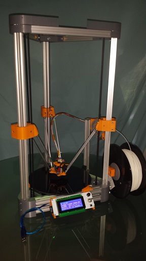
I've just published the latest iteration of my Cherry Pi printer, Cherry Pi II, on Thingiverse (http://www.thingiverse.com/thing:298168)
The major changes are :-
All electronics and PSU are now housed under the bed
Tower extrusions were reduced to 600mm to increase rigidity
Cross brace extrusions were reduced to 250mm
Delta rods were reduced to 200mm
Limit switches are now housed in the top printed apex pieces
Jhead mount re-designed to allow greater build height (270mm)
250mm diameter mirror used as print bed. 95mm print radius
Marlin firmware changed to Rich Cattell's fork
FSR Z probing installed
Printed T nuts used throughout (http://www.thingiverse.com/thing:28788)
Low friction spool mount
(http://www.thingiverse.com/thing:235925)
I'm looking at providing a complete kit of parts for anyone who is interested just PM me.
Andy
|
Re: Cherry Pi II Released April 13, 2014 03:46PM |
Registered: 10 years ago Posts: 903 |

|
Re: Cherry Pi II Released April 13, 2014 06:11PM |
Registered: 10 years ago Posts: 515 |
Hi. Yes the FSR force sensing resistors are installed and working great. You can see them on one of the Thingiverse images I posted. Cherry Pi II auto calibrates and auto bed levels. Cherry Pi II doesn't have a heated bed as it's designed to print PLA and, currently, there doesn't seem to be a way to have FSR probing and a heat bed. I'm sure someone much brighter than me will find a way and then ...
Cherry Pi III
Andy
Cherry Pi III
Andy
|
Re: Cherry Pi II Released April 13, 2014 07:27PM |
Registered: 10 years ago Posts: 140 |
|
Re: Cherry Pi II Released April 13, 2014 08:09PM |
Registered: 10 years ago Posts: 903 |
Quote
AndyCart
I'm sure someone much brighter than me will find a way and then ...
Cherry Pi III
I'm putting my money on you figuring it out before they do. Would the sensors read properly if you bonded standoffs to the glass, attached the heatbed to the standoffs with a cork insulator below, and stacked a second piece of glass on top as your heated print surface? I would think that it should be an adequate thermal break, if overheating the sensors is the concern.....
|
Re: Cherry Pi II Released April 14, 2014 01:41AM |
Registered: 10 years ago Posts: 515 |
Quote
3DRapidClone
By switching to a heated build chamber! I am interested in this proposed kit of yours! Would want to scale it up a bit. Do you like the magnetic effectors much more than the traxxas u-joint alternatives?
Much of the build time was spent sourcing materials and certain things, extrusion, screws, bearings, etc I bought in bulk to save on shipping costs. I figured I could put a complete kit of parts together for anyone who doesn't want the hassle of doing it themselves, it would also solve the eternal 'catch 22' that you need access to a printer to build a printer. I now have three working machines, my original Huxley, CP and CPII so I'm in a good position to produce the printed parts fairly quick. I managed to save to SD all the gcode for each part so I don't even need to hook the machines up to a PC to print off a parts kit. I also built a few jigs for machining the rod end cups and rods so that process is fairly simple to replicate too.
Magnetic connections to the effector are great. Easy to dismantle when required, reliable for printing and pretty much maintenance free. They look pretty cool to
Andy
|
Re: Cherry Pi II Released April 14, 2014 01:51AM |
Registered: 10 years ago Posts: 515 |
Quote
vreihen
Quote
AndyCart
I'm sure someone much brighter than me will find a way and then ...
Cherry Pi III
I'm putting my money on you figuring it out before they do. Would the sensors read properly if you bonded standoffs to the glass, attached the heatbed to the standoffs with a cork insulator below, and stacked a second piece of glass on top as your heated print surface? I would think that it should be an adequate thermal break, if overheating the sensors is the concern.....
I'm sure there are numerous ways to achieve FSR with a heated bed. I've already looked at a couple on the Google groups delta forum. A guy called Wing on there has done a fantastic job producing some code for a tiny arduino board that sorts out the major problem with FSR which is balancing the don't trigger with the weight of the bed/trigger when required without too much force from the hotend issue. I plan to have a look at this soon. The truth is I much prefer printing with PLA and don't really have much need, personally, for using a heat bed. That said my Huxley and the original Cherry Pi both have one. The only CPII part in ABS is the effector plate as it's very close to the hotend and it didn't want it melting. I have actually managed to get ABS to stick to my mirror build plate with no heat using a glue stick but I admit it's much easier on a heat bed.
Watch this space

I'm also working on a carriage design using printed 'bearings' rather than the, current, 6 x 623 bearings per slide. That's looking really promising.
Andy
|
Re: Cherry Pi II Released April 14, 2014 03:41AM |
Registered: 10 years ago Posts: 1,381 |
Quote
AndyCart
A guy called Wing on there has done a fantastic job producing some code for a tiny arduino board that sorts out the major problem with FSR which is balancing the don't trigger with the weight of the bed/trigger when required without too much force from the hotend issue.
Got a link to the code.
|
Re: Cherry Pi II Released April 14, 2014 06:53PM |
Registered: 10 years ago Posts: 515 |
|
Re: Cherry Pi II Released April 15, 2014 02:04PM |
Registered: 10 years ago Posts: 140 |
|
Re: Cherry Pi II Released April 15, 2014 03:14PM |
Registered: 10 years ago Posts: 20 |
The printer looks great Andy. I'm currently designing a delta printer which shares several characteristics with the Cherry Pi and I was just in the process of re-designing my base to contain all the electronics too. If I understand correctly, the second revision has become slightly shorter and wider. Is that down to stability issues or down to a desired print shape?
I'm also using the 250mm mirror as a print surface, but currently have 750mm extruded aluminium uprights.
I'm also using the 250mm mirror as a print surface, but currently have 750mm extruded aluminium uprights.
|
Re: Cherry Pi II Released April 15, 2014 03:24PM |
Registered: 10 years ago Posts: 903 |
RichRap's formula is to make the arm length 0.8 times the distance between two posts on a Delta printer:
http://richrap.blogspot.com/2013/12/3dr-build-tutorial-part4-firmware.html
http://richrap.blogspot.com/2013/12/3dr-build-tutorial-part4-firmware.html
Quote
RichRap's blog
I get asked a lot about building Bigger Delta printers. - Going higher is not a mystery you just extend everything taller. Going wider in X and Y is also quite easy, you just need to also extend the print arms. General relation in size of these arms is the horizontal distance between the vertical posts x 0.8
Eg - If you had a measurement of 600mm between two of the three posts a good arm length would be 600x0.8 = 480mm eye to eye.
If you make the arms longer you can print more outside of the vertical posts, That gets interesting when you have a really big platform because you have much more space to potentially use outside of the vertical posts, but it also uses up more vertical space with longer arms than you really need. Also be careful not to hit into these posts if you print very big things, most firmwares are dumb and do not know that you have vertical posts in the way of the printer's build envelope.
|
Re: Cherry Pi II Released April 15, 2014 05:19PM |
Registered: 10 years ago Posts: 140 |
|
Re: Cherry Pi II Released April 15, 2014 06:33PM |
Registered: 10 years ago Posts: 515 |
Quote
3DRapidClone
How did you figure out your custom Delta rod length? I am definitely interested in your kit though. Can you cut custom lengths of aluminum tubing for you kit?
I have built a few delta printers now and found that delta rod length isn't too critical. Richrap's 0.8 of the distance between towers is a really good rule of thumb. In Cherry Pi II that would have meant 250mm but I reduced it by 50mm as I wanted to retain a larger build height. It prints great. Probably a little on the small side as, ocassionally, at the extremes of the print area I have had a magnetic connector disengage. I will probably split the difference and go to 225mm. Simple to do.
I can cut the tubes to whatever length is required. Same goes for colours for the printed parts, addition of FSR probing, LCD display, etc. it's all customisable (is that even a word?
 )
)Andy
|
Re: Cherry Pi II Released April 15, 2014 06:41PM |
Registered: 10 years ago Posts: 515 |
Quote
ybanrab
The printer looks great Andy. I'm currently designing a delta printer which shares several characteristics with the Cherry Pi and I was just in the process of re-designing my base to contain all the electronics too. If I understand correctly, the second revision has become slightly shorter and wider. Is that down to stability issues or down to a desired print shape?
I'm also using the 250mm mirror as a print surface, but currently have 750mm extruded aluminium uprights.
The original had 800mm extrusion for the towers and it really wobbles about at high print speeds. That can only reduce quality. I rarely print anything over about 80mm tall so losing a 100mm of height wasn't an issue. It was also configured for a 300mm diameter build plate. Version 2 has 600mm towers but, as there is no heated bed, no separate limit switch mounts and shorter delta rods it still has 270mm build height. I also went for a smaller build plate as 250mm mirrors are easy to source and cheap plus the proportions look right.
I had to go for a 6A psu rather than a 20A in order to fit it under the bed. You can see from the photos that it's a tight squeeze. As I don't need a heated bed for CP II it wasn't an issue and as a bonus is much cheaper.
Andy
|
Re: Cherry Pi II Released April 15, 2014 10:37PM |
Registered: 10 years ago Posts: 140 |
|
Re: Cherry Pi II Released April 17, 2014 04:58PM |
Registered: 12 years ago Posts: 82 |
Nice work on the new model Andy. I've still not finished my Cherry Pi I...I finally got all the parts (and finally got hold of someones pillar drill!) but havn't had time.
Quick question - is this a complete redesign, or do you think it might be possible to mash the two together to essentially have v1 with the heated bed, and then things like the auto-leveling from v2?
Cheers and keep it up
Quick question - is this a complete redesign, or do you think it might be possible to mash the two together to essentially have v1 with the heated bed, and then things like the auto-leveling from v2?
Cheers and keep it up
|
Re: Cherry Pi II Released April 17, 2014 07:24PM |
Registered: 10 years ago Posts: 515 |
Hi Rick
Nice to hear you're nearly there. It is just a revamp of V1. You could easily convert your build. I've not figured a way to add both FSR probing and a heated bed yet. I've been busy playing around with some V wheels someone gave me from Open Builds. They are really cheap at £2.34 each. For that you get the v wheel, 2 x 625 bearings a shim a spacer and an M5 bolt. You only need three for each carriage and they work out cheaper than buying the 18 623 bearings. They run incredibly smoothly. I've designed a drop in replacement carriage that uses them. I played around with some printed sliders but didn't have much luck. They ran on the extrusion very smoothly but due to the position of the GT2 belt they kept jamming when run from the steppers. The angles were all wrong. I've also designed a new version of the CP II effector that has integral 25mm fan mounts rather than using CA to fix them. CP II is quickly becoming CP 2.5. I'll post the new files and some pictures over the weekend.
Andy
Nice to hear you're nearly there. It is just a revamp of V1. You could easily convert your build. I've not figured a way to add both FSR probing and a heated bed yet. I've been busy playing around with some V wheels someone gave me from Open Builds. They are really cheap at £2.34 each. For that you get the v wheel, 2 x 625 bearings a shim a spacer and an M5 bolt. You only need three for each carriage and they work out cheaper than buying the 18 623 bearings. They run incredibly smoothly. I've designed a drop in replacement carriage that uses them. I played around with some printed sliders but didn't have much luck. They ran on the extrusion very smoothly but due to the position of the GT2 belt they kept jamming when run from the steppers. The angles were all wrong. I've also designed a new version of the CP II effector that has integral 25mm fan mounts rather than using CA to fix them. CP II is quickly becoming CP 2.5
. I'll post the new files and some pictures over the weekend.Andy
|
Re: Cherry Pi II Released April 17, 2014 08:11PM |
Registered: 10 years ago Posts: 903 |
Quote
RickM
I finally got all the parts (and finally got hold of someones pillar drill!) but havn't had time.
For what it's worth, I made two sets of rod ends using a cordless hand drill with no problems. My magnetic spheres are 1/2 inch (12.7mm) though, and I used a 1/2 inch spherical cutting tool. One set of rods were M3 socket drives, and the other one was M5's. I just held the rod/screw in front of the drill, squeezed the trigger, and worked them slowly freehand.
Quote
AndyCart
I played around with some printed sliders but didn't have much luck. They ran on the extrusion very smoothly but due to the position of the GT2 belt they kept jamming when run from the steppers. The angles were all wrong.
Would they work any better if the belt was inside the T-slot groove with two "ears" sticking into the slot that attach to the belt?
My current Delta RepStrap is using V-slot and the mini-V wheels. The oblong spacers were pretty close to the edge of their adjustability range when I put them into the mini metal slider plate, and I don't think that I could find any more tension against the extrusion if they wear even a hair. Hopefully you will come up with a better adjuster mechanism than OpenBuilds did.....
|
Re: Cherry Pi II Released April 18, 2014 02:34AM |
Registered: 10 years ago Posts: 515 |
Hi guys
Vreihen, great idea re the rod ends. As the depth you need to cut is so shallow I guess you could also use a ball shaped grindstone in a Dremel type tool. I'm lucky enough to have a drill press so it was the obvious thing to use. RickM, if you are going to use a drill press, the way I did it was to tap an M5 hole in the centre of a peice of scrap mild steel 25 x 50 x 3, anything you have to hand would do. I secured this in the vice on the drill press. I then put a 4mm drill bit the wrong way round in the drill chuck I.e blunt end pointing down. Using this you can screw your M5 SHCS into the tapped hole in the scrap steel in the vice and line up the Allen hex in the SHCS with the drill bit I.e drop the bit into the hole. Then just swap the 4mm bit for the ball end mill and you are good to go. I found that I needed to mill down just to the edge of the hobbing on the head of the SHCS. This also means that about half of the hex socket is left intact to use for removing from the jig, screwing into the rod, etc.
Vreihen, I was given a set of three of the larger size V wheels from OB so used those. I fitted them to a 3d printed carriage at 42mm centres. This makes them a fairly tight fit on my Bosch/Rexroth extrusion, which already has a V on the slot. The spring in the PLA is, I think, enough to cope with any minimal wear that may occur. Have a look on Thingiverse later today. I will post some pictures. I really like the way it rolls so smoothly on the extrusion. It also gets rid of the nagging doubt about running steel bearings on aluminium, which, so far, has been perfectly fine but this way seems better. It also cheaper. I'm trying to get a really competent, fast and accurate design together for minimal cost and using the V wheels saves about £15. I'm going to investigate using Spectra line to replace the GT2 belts. This would save another £30 or so. I used this system when I built a 3DR and was very impressed with it.
The other improvement I have made is around the FSR bed probing. I managed to get very consistent triggering of the FSRs with fairly light hotend pressure but, due to the foam used to spread the weight of the mirror build plate across the FSR, to avoid false and/or permanent triggering, as the hotend probed at the tower bases I.e above the motors the build plate would tip a little. This caused inaccurate results. I've modified my bed retaining pieces to include an M3 screw that can be tightened so it just touches the mirror. Not enough to put pressure on the FSR but enough to stop the tipping. Pictures later also.
Andy
Edited 1 time(s). Last edit at 04/18/2014 05:54AM by AndyCart.
|
Re: Cherry Pi II Released April 18, 2014 02:54AM |
Registered: 10 years ago Posts: 515 |
Here are some images, and the .stl files for anyone interested in pursuing the printed tower slides idea. I've also attached my Sketchup design file.
You can see in the image below the UHMW tape I used on the edge of the slide to reduce friction. These actually worked very well but the belt geometry was all wrong on my machine. With a little work these could be a cheap way to go. I'm too busy with other stuff to pursue it at the moment though.
The nuts traps are to allow two M3 10mm screws to be used on each of the 3 adjustable sliders.
These were printed on CP II at 120mm/sec as they were just prototypes. I need to work out what retraction to use at this speed as I seem to be getting atrefacts on the side walls. None evident at more normal speeds. I usually print 'good stuff' at 40mm/S.
Andy
Edited 2 time(s). Last edit at 04/18/2014 03:32AM by AndyCart.
You can see in the image below the UHMW tape I used on the edge of the slide to reduce friction. These actually worked very well but the belt geometry was all wrong on my machine. With a little work these could be a cheap way to go. I'm too busy with other stuff to pursue it at the moment though.
The nuts traps are to allow two M3 10mm screws to be used on each of the 3 adjustable sliders.


These were printed on CP II at 120mm/sec as they were just prototypes. I need to work out what retraction to use at this speed as I seem to be getting atrefacts on the side walls. None evident at more normal speeds. I usually print 'good stuff' at 40mm/S.
Andy
Edited 2 time(s). Last edit at 04/18/2014 03:32AM by AndyCart.
|
Re: Cherry Pi II Released April 18, 2014 03:29AM |
Registered: 10 years ago Posts: 515 |
Below are the images and files for the amendments I made to the tower carriages to use V wheels from Open Builds :-
Open Builds V Wheel
The more astute of you will notice that I've already changed the design a little from the attached image to make it a bit prettier
I've attached the .stl file on Thingiverse (it was too large to attach here) if you want to print it. BTW the one in the image was printed on CP II at 80mm/S
[www.thingiverse.com]
I've also amended the bed clip to stop tilt when probiing
The other change I've made is to the length of the delta rods. I've gone from 200mm to 250mm. The 200mm version worked o.k but the magnets were at their limits out toward the edge of the bed. The reliable print area was about 170mm x 170mm, albeit with a 270mm build height. The change to 250mm rods gives a 200mm x 200mm x 200mm build envelope and the magnets are very secure and reliable.
Andy
Edited 2 time(s). Last edit at 04/18/2014 06:27AM by AndyCart.
Open Builds V Wheel


The more astute of you will notice that I've already changed the design a little from the attached image to make it a bit prettier

I've attached the .stl file on Thingiverse (it was too large to attach here) if you want to print it. BTW the one in the image was printed on CP II at 80mm/S
[www.thingiverse.com]
I've also amended the bed clip to stop tilt when probiing
The other change I've made is to the length of the delta rods. I've gone from 200mm to 250mm. The 200mm version worked o.k but the magnets were at their limits out toward the edge of the bed. The reliable print area was about 170mm x 170mm, albeit with a 270mm build height. The change to 250mm rods gives a 200mm x 200mm x 200mm build envelope and the magnets are very secure and reliable.

Andy
Edited 2 time(s). Last edit at 04/18/2014 06:27AM by AndyCart.
|
Re: Cherry Pi II Released April 18, 2014 05:49AM |
Registered: 10 years ago Posts: 515 |
Someone asked me to modify the base stepper mount as the stepper fixing screws were hard to get to/adjust.
Just uploaded it to Thingiverse
Just uploaded it to Thingiverse

|
Re: Cherry Pi II Released April 18, 2014 08:22AM |
Registered: 10 years ago Posts: 553 |
Quote
AndyCart
Here are some images, and the .stl files for anyone interested in pursuing the printed tower slides idea. I've also attached my Sketchup design file.
You can see in the image below the UHMW tape I used on the edge of the slide to reduce friction. These actually worked very well but the belt geometry was all wrong on my machine. With a little work these could be a cheap way to go. I'm too busy with other stuff to pursue it at the moment though.
The nuts traps are to allow two M3 10mm screws to be used on each of the 3 adjustable sliders.
[attachment 31016 PrintedSlides2.jpg]
[attachment 31017 PrintedSlides1.jpg ]
These were printed on CP II at 120mm/sec as they were just prototypes. I need to work out what retraction to use at this speed as I seem to be getting atrefacts on the side walls. None evident at more normal speeds. I usually print 'good stuff' at 40mm/S.
Andy
Im putting the final touches on my own version of a printed slider, but with an integrated carriage. I am curious though, wouldn't having the side-to-side adjustablilty for the slider only on one side cause it to become off center as it wears?
Also, great idea with the motor screw holes. I dont know why they were not used in the original Kossel.
greghoge.com
HUGE 3D PRINTER PARTS SALE!!!
|
Re: Cherry Pi II Released April 18, 2014 12:04PM |
Registered: 10 years ago Posts: 515 |
Quote
gmh39
Quote
AndyCart
Here are some images, and the .stl files for anyone interested in pursuing the printed tower slides idea. I've also attached my Sketchup design file.
You can see in the image below the UHMW tape I used on the edge of the slide to reduce friction. These actually worked very well but the belt geometry was all wrong on my machine. With a little work these could be a cheap way to go. I'm too busy with other stuff to pursue it at the moment though.
The nuts traps are to allow two M3 10mm screws to be used on each of the 3 adjustable sliders.
[attachment 31016 PrintedSlides2.jpg]
[attachment 31017 PrintedSlides1.jpg ]
These were printed on CP II at 120mm/sec as they were just prototypes. I need to work out what retraction to use at this speed as I seem to be getting atrefacts on the side walls. None evident at more normal speeds. I usually print 'good stuff' at 40mm/S.
Andy
Im putting the final touches on my own version of a printed slider, but with an integrated carriage. I am curious though, wouldn't having the side-to-side adjustablilty for the slider only on one side cause it to become off center as it wears?
Also, great idea with the motor screw holes. I dont know why they were not used in the original Kossel.
Hi Greg
I had made the assumption that, due to the use of the UHMW tape, there would be negligible wear. If there was I would have just used a new piece of tape! It is only the slider directly behind the carriage face that isn't adjustable and it's mating slider is. Any slack could be taken up from the other side.
Andy
Edited 1 time(s). Last edit at 04/18/2014 12:06PM by AndyCart.
|
Re: Cherry Pi II Released April 18, 2014 02:22PM |
Registered: 10 years ago Posts: 553 |
Ah, ok. I didn't notice the 3rd adjustable slider sitting on the table.
greghoge.com
HUGE 3D PRINTER PARTS SALE!!!
greghoge.com
HUGE 3D PRINTER PARTS SALE!!!
|
Re: Cherry Pi II Released April 22, 2014 05:19PM |
Registered: 9 years ago Posts: 9 |
Hi Andy, is there any chance you or anyone else who's reading this could modify this Rostock mini carriage to mount flush on this V Wheel Carriage from your Cherry Pi II? Here are the CAD files for the Rostock carriage.
Cheers!
Neil
Cheers!
Neil
|
Re: Cherry Pi II Released April 23, 2014 06:52AM |
Registered: 10 years ago Posts: 515 |
Quote
DeltaDroid
Hi Andy, is there any chance you or anyone else who's reading this could modify this Rostock mini carriage to mount flush on this V Wheel Carriage from your Cherry Pi II? Here are the CAD files for the Rostock carriage.
Cheers!
Neil
Hi Neil
It's on Thingiverse for you.
Andy
|
Re: Cherry Pi II Released May 20, 2014 12:27AM |
Registered: 9 years ago Posts: 113 |
|
Re: Cherry Pi II Released May 20, 2014 05:33PM |
Registered: 10 years ago Posts: 515 |
Hi nka
It works great. I'll try and get a BOM together for you. I've also amended a couple of parts, the carriages to use mini V wheels and the effector to use it as a Z probe. I'll post on Thingiverse later this week. Most of the noise is from the steppers but tweaking the resistors on the drivers helps loads. As per hydroraptors blog.
andy

Sorry, only registered users may post in this forum.