Grounded Experimental Delta Printer
Posted by nicholas.seward
|
Grounded Experimental Delta Printer May 08, 2013 03:07AM |
Registered: 10 years ago Posts: 979 |
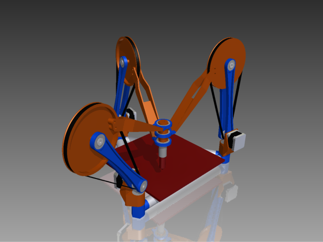
I am pleased to present my first design iteration.
Features:
Watch the video and let me know what you think. (The belts are actually going to be tensioned 80lb SpiderWire.)
Edited 2 time(s). Last edit at 05/08/2013 09:40AM by nicholas.seward.

Features:
- Low vitamin count
- Low friction (Nema14!)
- Low center of gravity
- Low weight
- Can fold flat with some quick disassembly
- Only 2 bearings will need to be special ordered
- Printable on a 150mmx150mm plate
- Around 8" diameter by 8" tall work envelope
- 9 unique printed parts
Watch the video and let me know what you think. (The belts are actually going to be tensioned 80lb SpiderWire.)
Edited 2 time(s). Last edit at 05/08/2013 09:40AM by nicholas.seward.
|
Re: Grounded Experimental Delta Printer May 08, 2013 03:26AM |
Admin Registered: 16 years ago Posts: 13,886 |
... with this big distances between the three bushings on the tool it would twist/bend while moving -- no chance for enough rigidity, even full metal parts won't be 'stiff' enough ...
Viktor
--------
Aufruf zum Projekt "Müll-freie Meere" - [reprap.org] -- Deutsche Facebook-Gruppe - [www.facebook.com]
Call for the project "garbage-free seas" - [reprap.org]
Viktor
--------
Aufruf zum Projekt "Müll-freie Meere" - [reprap.org] -- Deutsche Facebook-Gruppe - [www.facebook.com]
Call for the project "garbage-free seas" - [reprap.org]
|
Re: Grounded Experimental Delta Printer May 08, 2013 03:43AM |
Registered: 10 years ago Posts: 979 |
@VDX: Possibly. However, those are ball bearings on the tool. I think the low level of friction will make this work. I will try a mock up and see if it fails miserably.
In my mind (an admittedly scary place), rigidity would increase at first as the distance between the tool mount points increase.
Do you have any ideas on how you would sure up the design?
In my mind (an admittedly scary place), rigidity would increase at first as the distance between the tool mount points increase.
Do you have any ideas on how you would sure up the design?
|
Re: Grounded Experimental Delta Printer May 08, 2013 04:02AM |
Admin Registered: 16 years ago Posts: 13,886 |
... instead of 3 ball bearings I'll print/assemble a two-story horizontal ring-bearing - the middle ring will have two ring-grooves on top and bottom, the two outer only one ring-groove facing to the middle ring ... then fill enough balls in the grooves and spring-compress the assembly against the base-ring (preferrably the bottom one), to which the toolhead is attached too ...
Viktor
--------
Aufruf zum Projekt "Müll-freie Meere" - [reprap.org] -- Deutsche Facebook-Gruppe - [www.facebook.com]
Call for the project "garbage-free seas" - [reprap.org]
Viktor
--------
Aufruf zum Projekt "Müll-freie Meere" - [reprap.org] -- Deutsche Facebook-Gruppe - [www.facebook.com]
Call for the project "garbage-free seas" - [reprap.org]
|
Re: Grounded Experimental Delta Printer May 08, 2013 04:13AM |
Registered: 10 years ago Posts: 979 |
I am not following. (I am not sure if you are saying this but I could instead of using one bearing for each connect point I could use two and increase my rigidity.)
Side note: there is only really a need for two bearings. The arm that attaches to the middle can attach directly to the tool holder. For the animation, I saved time by making them all the same but when I get ready to print I will definitely want to get rid of one bearing. Also, I just stuck a UBIS in the design. I realize that I need to minimize the length of the hot end because any wiggle will get magnified toward the end of the nozzle. I will gladly take suggestions on that too. The RepRap Morgan probably has the closes design to this. I will dig through Quentin Harley's plans when he releases them soon.
Edited 1 time(s). Last edit at 05/08/2013 04:18AM by nicholas.seward.
|
Re: Grounded Experimental Delta Printer May 08, 2013 04:58AM |
Admin Registered: 16 years ago Posts: 13,886 |
... here a fast sketch - the 'bearing-storeys' are rings with grooves for the balls, so they can rotate free horizontally ... you have to add some compression system for joining the three 'storeys':
Edited 1 time(s). Last edit at 05/08/2013 05:03AM by VDX.
Viktor
--------
Aufruf zum Projekt "Müll-freie Meere" - [reprap.org] -- Deutsche Facebook-Gruppe - [www.facebook.com]
Call for the project "garbage-free seas" - [reprap.org]

Edited 1 time(s). Last edit at 05/08/2013 05:03AM by VDX.
Viktor
--------
Aufruf zum Projekt "Müll-freie Meere" - [reprap.org] -- Deutsche Facebook-Gruppe - [www.facebook.com]
Call for the project "garbage-free seas" - [reprap.org]
|
Re: Grounded Experimental Delta Printer May 08, 2013 05:12AM |
Registered: 10 years ago Posts: 979 |
|
Re: Grounded Experimental Delta Printer May 08, 2013 08:58AM |
Registered: 11 years ago Posts: 248 |
|
Re: Grounded Experimental Delta Printer May 08, 2013 09:37AM |
Registered: 10 years ago Posts: 979 |
Your right. There are 22 bearings total. However, they are all cheap inline skate bearings except for the 2 on the tool. (Note: my Printrbot has 6 rods, 10 linear bearings, 2 threaded rods, and 5 bearings.)
It would be very hard to make without a 3D printer. Luckily, I have a 3D printer. (You would have to make/get a RepStrap to be able to make this RepRap. Standard RepRap plans are usually hard to make without a RepRap. I am sure I could do a redesign with only garage tools in mind.) Also, right know there are only 9 unique parts. Everything has radial symmetry. Additionally, I could get rid of 6 of the bearings between the lower arms and the upper arms. A simple pin connection would be more than sufficient. (I am going to spend the extra $6 for less friction and symmetry.) That would bring the total to 16 bearings. That is exactly how many bearings (linear and radial) that a Printrbot has.
I may be biased but I would say the design is simpler than the other RepRaps. (I am psuedo-measuring this with part count, part complexity, plastic volume, assembly time, etc.) The firmware, however, will not be so simple but electrons are cheap.
Edited 1 time(s). Last edit at 05/08/2013 09:51AM by nicholas.seward.
|
Re: Grounded Experimental Delta Printer May 08, 2013 10:16AM |
Registered: 11 years ago Posts: 265 |
Interesting concept for sure.
But it looks like it may be an inertia nightmare with that large wheels in the air.
I'm assuming you calculated the required torque, and those belt ratios are the reason for them being so big.
But I think going back to NEMA 17's and reducing the size of those wheels would be a better 'first attempt' at the concept.
EDIT: Thinking about it even more, considering the distance traveled, you could leave the motors at the bottom, get rid of the wheel and betls, and run a threaded rod up to arm.
You could then go back to NEMA 14's, and since it's a screw you get the torque back.
Edited 1 time(s). Last edit at 05/08/2013 10:20AM by ShadowRam.
|
Re: Grounded Experimental Delta Printer May 08, 2013 10:58AM |
Registered: 10 years ago Posts: 979 |
@ShadowRam: If I print them solid (which I won't) the top pulleys will weight 40g each. However, I have not worked to optimize their size yet. I was trying to get a proof of concept down on paper so I could better think about the next steps.
Now that I am focusing on the torque needed, the design as is can produce up to 4N forces from each arm. A quick calculation shows that my Printrbot is producing more than 100N in the x and y directions. That is a huge difference for sure. I think I will take your advice and bump up to the Nema17. That change alone will bump up the force to 14N. However, the Nema17 weighs more than 2 times what the Nema14 does. (Not really an issue due to it being mounted close to an axis.) 14N per arm may be enough with such a small dynamic load. However, I will probably need to adjust the small pulley down and make the large pulley bigger. With what I consider small hard to notice changes, I can hit 24N per arm. (.75" x 4" changed to .5" x 4.5")
I estimate that the dynamic load will be around 200g. To accelerate 200g at 5g, I will only need a net force of 10N.
I think that settles it. Nema14 was wishful thinking.
EDIT: I made some math mistakes. I was doing some quick napkin calculations. All of the above numbers are gross estimates.
Edited 1 time(s). Last edit at 05/08/2013 11:27AM by nicholas.seward.
|
Re: Grounded Experimental Delta Printer May 08, 2013 11:04AM |
Registered: 10 years ago Posts: 979 |
Interesting idea about the screw. Depending on arrangement, it could impede on the work envelope but I think that can be addressed. (I only worry about backlash.) I think it is a very workable idea. I am going to experiment with the belt/string drive to see if it is feasible. Speed is more important to me than small steppers. In fact, the Nema17 motors are 15% cheaper than the Nema14 ones I wanted.
|
Re: Grounded Experimental Delta Printer May 08, 2013 11:55AM |
Registered: 11 years ago Posts: 265 |
|
Re: Grounded Experimental Delta Printer May 08, 2013 12:07PM |
Registered: 10 years ago Posts: 979 |
|
Re: Grounded Experimental Delta Printer May 08, 2013 03:29PM |
Registered: 11 years ago Posts: 265 |
nicholas.seward Wrote:
-------------------------------------------------------
> Very true. However, I am dreaming of insane
> accelerations that will generate forces that
> overshadow gravity.
You'll need a stiff system then.
The rotational point down by the motors, how do you prevent 'wobble' by the time you get up to the large wheels?
Since the arms are cantilevered from the base, any slight deflection will throw your accuracy at the extruder off by quite a bit.
|
Re: Grounded Experimental Delta Printer May 08, 2013 04:08PM |
Registered: 10 years ago Posts: 979 |
Experimentation will have to verify this but I think this setup will be wobble tolerant. The large wheels should be able to shake back and forth normal to their surface and the separation between steppers and the tool should remain relatively constant. A typical delta robot would articulate at the ground joint but I am articulating from the mid-joint. (To be technical, a typical delta cantilevers it first arm with respect to the base. My design has the arms cantilevered with respect to each other.) I am worried that two 7 inch arms with the angle maintained by SpiderWire will have too much give. If that is the case, I will switch to a belt. However, all my research seems to indicate that properly tensioned SpiderWire will work like a champ.
All that said, I want a machine that can walk or crawl and hopefully scribble its name. Maybe later the machine will run or skydive and make works of art. This is new territory for me and if I am not messing up them I am not working hard enough.
Edited 1 time(s). Last edit at 05/08/2013 04:12PM by nicholas.seward.
|
Re: Grounded Experimental Delta Printer May 09, 2013 12:51PM |
Registered: 10 years ago Posts: 979 |
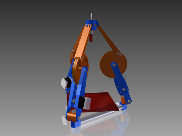
Well, I have been getting lots of good feed back and am almost done with my second iteration. I have remodeled all the parts. All bearings are now captive. (They don't rely on being pressfit.) The motors have been upsized to Nema17 and moved up onto the arms. I kept them as low on the arms as possible. This will let me have a longer smaller diameter driving pulley. I also increased the size of the bearings on the tool holder and use two for each arm attachment. One arm doesn't need any bearings for its attachment. I also made all the attachment to the tool holder happen in one plane to keep the math easier.
I also fractionally increased the size of the large pulley after doing some torque calculations. I have been getting lots of flack for them being so large. My calculations tell me that their mass will be 40g if printed solid. I am very certain that the pulley's mass won't be the weak part of the system. One problem that was pointed out to me was that without an enclosure it is hard to tell if something from the environment is in the way. I think this can be accomplished with a lightweight shroud around the bottom.
The picture is missing bolts, nuts, strings, drive-pulleys and extruder.
TODO:
Edited 4 time(s). Last edit at 05/09/2013 04:10PM by nicholas.seward.
I also fractionally increased the size of the large pulley after doing some torque calculations. I have been getting lots of flack for them being so large. My calculations tell me that their mass will be 40g if printed solid. I am very certain that the pulley's mass won't be the weak part of the system. One problem that was pointed out to me was that without an enclosure it is hard to tell if something from the environment is in the way. I think this can be accomplished with a lightweight shroud around the bottom.

The picture is missing bolts, nuts, strings, drive-pulleys and extruder.
TODO:
- Add tensioner onto large pulley. (Should be easy.)
- Select hot end and filament drive setup. (I need a recommendation on a hot end that will allow me to minimize the distance been the arm connection plane and the nozzles tip.)
- Homing scheme
Edited 4 time(s). Last edit at 05/09/2013 04:10PM by nicholas.seward.
|
Re: Grounded Experimental Delta Printer May 09, 2013 01:30PM |
Registered: 11 years ago Posts: 265 |
|
Re: Grounded Experimental Delta Printer May 09, 2013 04:19PM |
Registered: 10 years ago Posts: 979 |
I forgot to add that to my todo list. I have a few ideas. I think I will use your idea. Instead of a hole, I will make a slot. During homing each arm with travel to the light/dark interface. You can have adjustment built in that will allow you to rotate the slot to different places on the wheel. I am going to use the nozzle touching the center of the bed as the homing position.
|
Re: Grounded Experimental Delta Printer May 09, 2013 04:57PM |
Admin Registered: 16 years ago Posts: 13,886 |
... instead of homing you could use some high-res encoding data on the disks, so after power up the actual absolute position can be read by rotating the disks until the nearest encoding raster is sensed ...
Viktor
--------
Aufruf zum Projekt "Müll-freie Meere" - [reprap.org] -- Deutsche Facebook-Gruppe - [www.facebook.com]
Call for the project "garbage-free seas" - [reprap.org]
Viktor
--------
Aufruf zum Projekt "Müll-freie Meere" - [reprap.org] -- Deutsche Facebook-Gruppe - [www.facebook.com]
Call for the project "garbage-free seas" - [reprap.org]
|
Re: Grounded Experimental Delta Printer May 09, 2013 05:58PM |
Registered: 12 years ago Posts: 23 |
Interesting!
For Homing on Morgan I use a small magnet inserted into a hole in the disk, with a digital hall effect sensor as limit switch. Because the magnet moves sideways, the switching range of the polarity dependent switch is very small, making it quite accurate.
I am allergic to anything optical. Real job is medical imaging systems, and opto sensors on moving parts are prone to dust, dirt. yellowing due to heat etc.
|
Re: Grounded Experimental Delta Printer May 10, 2013 04:15AM |
Registered: 10 years ago Posts: 979 |

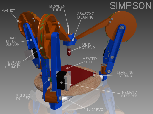
Here it is complete with hall effect sensors, extruder, adjustable heated bed, string, bolts, and nuts. All I have left to do is pick a filament drive and make a nice package that includes the power supply, electronics, filament drive, and spool.

Here is the home position. The arms are in the 180 degree position. During normal operations there is no need to go past this position so it is a perfect end stop location. The nozzle is about 10 inches from the heated bed. I will put the approximate separation in the firmware. I will then level the bed to match what the printer is doing. Bingo-Bango. My Printrbot will be harder to calibrate after the initial setup.
I need to make a model of the working envelope because it is pretty strange. To further confuse the issue, the work envelope changes for different parts. (Max part height will decrease as the part widens due to interference from the big wheels.) Bottom line, you can print a 6" cube with no problem.
I am trying on the name "Simpson" for this design. George Gaylord Simpson came up with the theory of Quantum Evolution to explains the rapid emergence of higher taxonomic groups. I thought that it was appropriate for such a radical design. What do you guys think? I am open to suggestions.
I am going to live with this design for a week or two to see if anything shakes loose. If nothing convinces me in that time that I am completely insane, I will order parts and start printing. If I can convince my wife, I am going to buy parts for two. Simpson0 needs to be able to replicate. I am calculating the vitamin bill will be $400/machine.
Edited 2 time(s). Last edit at 05/10/2013 04:15AM by nicholas.seward.
|
Re: Grounded Experimental Delta Printer May 10, 2013 05:32AM |
Registered: 11 years ago Posts: 254 |
have you looked at kossels fishing lines pullys and the ideas behind? [www.youtube.com]
the lines are fixed with screws on the wheel and doesn't depend on friction for driving the wheels
the lines are fixed with screws on the wheel and doesn't depend on friction for driving the wheels
|
Re: Grounded Experimental Delta Printer May 10, 2013 07:30AM |
Registered: 15 years ago Posts: 401 |
|
Re: Grounded Experimental Delta Printer May 10, 2013 08:39AM |
Registered: 15 years ago Posts: 401 |
Hah. Couldn't stop thinking about it so I did the math. You may have some trouble with the speed of the controller, because the coordinate transformation takes some heavy lifting as far as the math goes.
You have three input variables: the three angles of the elbow joints, Aa, Ab, Ac. You have three outputs: x,y,z. We need to go the opposite direction.
There are ten givens.
The three base vectors. These are the offsets between the origin and the centre of the horizontal shoulder joint.
Ba = <xa,ya,za>
Bb = <xb,yb,zb>
Bc = <xc,yc,zc>
The horizontal offset between the horizontal shoulder joint and the vertical shoulder joint; positive if the vertical joint is more central than the horizontal one, negative otherwise.
sx
The length between the nozzle's central axis and the attachment point of the arm.
nx
The height of each arm's nozzle bearing above the nozzle.
nva,nvb,nvc
The scalar lengths of the two arm segments
l1, l2
Note that I am assuming that Ba,Bb,Bc are at the centre of the horizontal shoulder joint's axis, but at the height of the vertical shoulder joint's axis. With that out of the way, here's the math:
Let P be the position vector of the nozzle. P = <x,y,z>
Let Ha,Hb,Hc be the vector between each Bx and the nozzle.
Ha = P-Ba
Hb = P-Bb
Hc = P-Bc
(9 subtractions)
Let ra,rb,rc be the cylindrical, radial distance from each, respective shoulder joint's horizontal axis to the nozzle
ra = sqrt(Ha_x^2 + Ha_y^2)
rb = sqrt(Hb_x^2 + Hb_y^2)
rc = sqrt(Hc_x^2 + Hc_y^2)
(6 multiply, 3 add, 3 sqrt)
Where Ha_x is the x-component of Ha, Ha_y is the y-component of Ha, etc.
Let la,lb,lc be the length of each, respective arm from the vertical shoulder to the wrist joint.
la = sqrt( (ra-sx-nx)^2 + (Ha_z + nva)^2 )
lb = sqrt( (rb-sx-nx)^2 + (Hb_z + nvb)^2 )
lc = sqrt( (rc-sx-nx)^2 + (Hc_z + nvc)^2 )
(6 multiply, 6 add, 3 subtract)
Calculate the angle of the elbow, based on the wrist-to-shoulder length
Aa = arccos((l1^2 + l2^2 - la^2)/(2*l1*l2))
Ab = arccos((l1^2 + l2^2 - lb^2)/(2*l1*l2))
Ac = arccos((l1^2 + l2^2 - lc^2)/(2*l1*l2))
(3 subtract, 3 divide, 3 arccos)
(There's an optimization here in not taking the square root in the previous step, and not squaring the same variable in this step)
The overall complexity of a single position calculation is:
24 add/sub
12 multiplies
3 divisions
3 sqrt
3 arccos
If you're clever, you can probably reduce the divisions to bit shifts. You can't do much about the rest.
Edited 2 time(s). Last edit at 05/10/2013 08:57AM by Annirak.
|
Re: Grounded Experimental Delta Printer May 10, 2013 09:33AM |
Registered: 11 years ago Posts: 265 |
VDX Wrote:
-------------------------------------------------------
> ... instead of homing you could use some high-res
> encoding data on the disks, so after power up the
> actual absolute position can be read by rotating
> the disks until the nearest encoding raster is
> sensed ...
Even easier, especially if you want to go the reprap cheap way.
Use a potentiometer. Even one out of a hobby servo.
This will give you absolute encoding to any resolution you want without the need for encoded disks or optics.
|
Re: Grounded Experimental Delta Printer May 10, 2013 10:12AM |
Registered: 15 years ago Posts: 401 |
ShadowRam Wrote:
-------------------------------------------------------
> This will give you absolute encoding to any
> resolution youwant can afford without the need for encoded
> disks or optics.
High-res, low noise ADC's are expensive. This is compounded by this design having between 90 and 180 degrees of play. A typical pot gives you between 270 and 360 degrees of rotation. Also, pots wear out. Frequently inconsistently.
-------------------------------------------------------
> This will give you absolute encoding to any
> resolution you
> disks or optics.
High-res, low noise ADC's are expensive. This is compounded by this design having between 90 and 180 degrees of play. A typical pot gives you between 270 and 360 degrees of rotation. Also, pots wear out. Frequently inconsistently.
|
Re: Grounded Experimental Delta Printer May 10, 2013 10:20AM |
Registered: 10 years ago Posts: 979 |
|
Re: Grounded Experimental Delta Printer May 10, 2013 10:54AM |
Registered: 15 years ago Posts: 401 |
nicholas.seward Wrote:
-------------------------------------------------------
> Above you guys can see that I will use cheapo hall
> effect homing. There will be no need for a full
> feedback loop. I like the idea of using the
> encoded desk or potentiometer but I am opting for
> the simpler design.
That makes sense. Failure-resistant sensing methods are definitely better and a magnet + hall sensor is a good step in that direction. I would ask, though, what kind of precision you can expect with that setup. What about a magnetic angular encoder? [www.digikey.com]
|
Re: Grounded Experimental Delta Printer May 10, 2013 11:37AM |
Registered: 11 years ago Posts: 265 |
Annirak Wrote:
-------------------------------------------------------
> ShadowRam Wrote:
> --------------------------------------------------
> -----
> > This will give you absolute encoding to any
> > resolution you want can afford without the need
> for encoded
> > disks or optics.
>
> High-res, low noise ADC's are expensive. This is
> compounded by this design having between 90 and
> 180 degrees of play. A typical pot gives you
> between 270 and 360 degrees of rotation. Also,
> pots wear out. Frequently inconsistently.
[canada.newark.com]
$2
Geared and multi-turn pots have been replacing encoder disks in all manner of automation industries.
Not that he would need a multi-turn in this application.
A lot of these pot's are now rated for 10 million turns.
So if you had one do a 'full' turn, every second, every day, every year.. You'd be good for > 7 years....
If it wears out after that time, you replace it for 1/10 of the cost it would for a full encoder setup.
Edited 1 time(s). Last edit at 05/10/2013 11:41AM by ShadowRam.


Sorry, only registered users may post in this forum.